Analysis of super structure building with plan and elevation irregularities using response spectrum method
Dheekshith K1 , Kishor Hegde21Assistant Professor, Dept. of Civil Engineering, Srinivas University Institute of Engineering and Technology, Karnataka, India

2 M.Tech student, Dept. of Civil Engineering, Srinivas University Institute of Engineering and Technology, Karnataka, India
Abstract - When there is an earthquake, the ground vibrates, causing the structures that are supported by it to move. Plan with vertical abnormalities, irregularity in strength and stiffness,massirregularity,tensionalirregularity, and other variables allcontributetostructuraldamage during earthquakes. So we need to how response spectrum analysis to evaluate the performance of irregular buildingwithtorsion irregularity in plan and vertical geometric irregularity in elevation. So We Use Different shape model was used like rectangle, L, T and U. And application of shear walls in the model. To understand the effects of earthquake on the different structure modeled. Analyzing thebuildingsinETABS software to carry out the storey displacements,storydrift,and torsional irregularity ratio of regular andirregularstructures and compare the results of different models.
Key Words: Super Structure ,Etabs, Irregularities Building, Response Spectrum Method, Torsional Irregularity Ratio
1. INTRODUCTION
Arock'sunstablebreaking,whichresultsinanearthquake,is the result of the tension being released as waves. The naturallyoccurringrisksthataretypicallyunanticipatedare earthquakes. The main earthquake often lasts only a few seconds to a minute or so, and it is often rather brief. Generallyspeaking,thereareusuallytwoormoresignificant peaksofmotionduringanearthquake.Thesepeaksindicate earthquake'sgreatestinfluence.
The act of ignoring how earthquakes affect buildings and using subpar construction methods are two major errors thatposeaseriousthreattostructures,asearthquakesare themostperilousnaturaloccurrencethatcausessubstantial devastation.Therefore,comprehendingtheseismicimpacts onbuildingsiscrucial,andcontractorsanddesignersmust takeintoaccounttheeffectsofseismicforcesonstructures toestablishpreventivemeasuresagainstpotentialcollapses andfailures.
Thedevastationcausedbyearthquakesonstructuresmakes itthemosthazardousnaturalphenomenon.Neglectingthe impact of earthquakes on buildings and using inferior construction techniques are the two primary causes of endangeringstructures.Hence,itisvitaltocomprehendthe seismic effects on structures. To prevent collapses and failures, designers and contractors must recognize the influence of seismic forces on buildings and incorporate preventivemeasures.
1.1 Seismic Designs And Philosophy
The major members might receive damage that can be repairedduringstrongbutinfrequentshaking,whileother parts of the structure might sustain damage that would require replacement after the earthquake. The building's majormembersmayincursignificantdamage,butitshould notcollapse.
As a result, following mild tremors, building will be fully functioninginshortperiod,withlittlerepairexpenses.After thedamagedmajormembersarerepairedandstrengthened, thebuildingwillbeoperationalaftermildshaking.
1.2 Response Spectrum Analysis
Response spectrum analysis (RSA) is a method used in seismicengineeringtoestimatethedynamicresponseofa structure to earthquakes or other types of dynamic loads. Theanalysisinvolvesplottingthemaximumresponseofa structureatdifferentfrequenciestoastandardizedground motion,representedasa"spectrum."ThegoalofRSAisto estimate the maximum displacement, velocity, and acceleration of a structure during an earthquake and to identifywhichpartsofthestructurearemostsusceptibleto damage. This information is used to design and retrofit structures to better resist seismic loads and ensure the safety of the people and assets they contain. RSA is a simplified method that provides a quick estimate of the seismic response of a structure, and it is typically used in conjunctionwithmoredetaileddynamicanalysismethodsto ensureaccurateresults.
1.3 Objectives
Toconductaresponsespectrumanalysistoevaluate theperformanceofirregular buildingwithtorsion irregularity in plan and vertical geometric irregularityinelevation.
Differentshapemodelwasusedlikerectangle,L,T andU.Andapplicationofshearwallsinthemodel.
To understand the effects of earthquake on the differentstructuremodeled.
To ensure that the structure is safe due to irregularities.Inaddition,effortsarebeingmadeto eliminatetheirregularitiesbymodifyingtheshear wallposition.
AnalyzedthebuildingsinETABSsoftwaretocarry out the storey displacements, story drift, and torsionalirregularityratioofregularandirregular structures and compare the results of different models.
2. METHODOLOGY
Structural analysis of mathematical model is needed to estimate force and displacement demands on various components of the structure in order to obtain seismic performance evaluation results. To forecast the seismic performanceofthestructures,severalanalyticalapproaches, bothelasticandinelastic,areavailable.
A response spectrum analysis can be used to study the various types of response of a building. For the lateral stressesgeneratedbytheETABSsystem,IS1893-2016(part 1) specifies seismic zone IV and a 5 percent damped responsespectrum.Theeigenvalueproblemofthemodelis used to derive the natural periods' basic values as part of ETABS.Thetotalseismicloadgeneratedanditsdistribution along the height correspond to the mass and stiffness distribution simulated by ETABS. Based on the modal frequency and modal mass, respectively, they are then integrated to approximate the entire response of the structure.
CalculationsasperIS1893(part1)2016,IS13920:1993& ASCE7-10.ModellingofthestructureusingETABS.Analysis ofthemodelfordifferentcases.Observation,tabulation,and interpretationoftheresults.
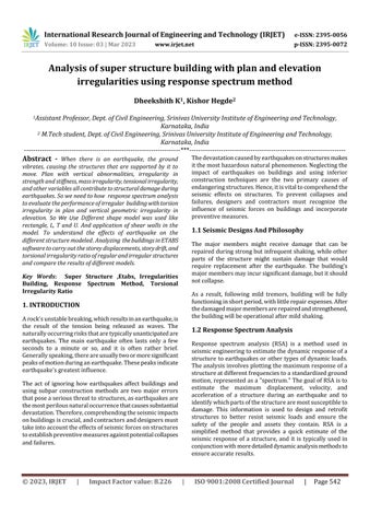
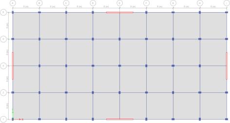
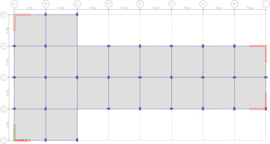
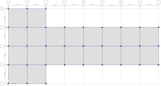
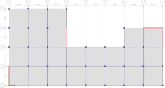
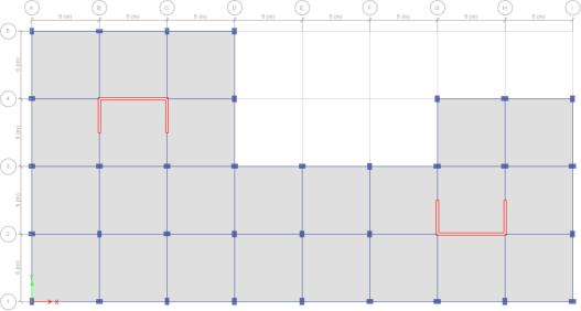
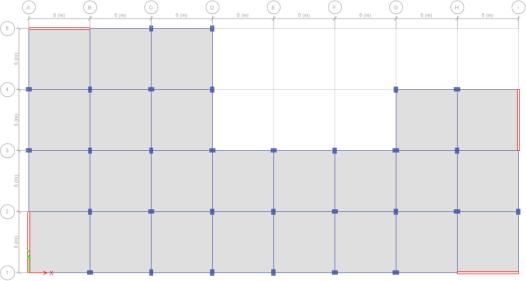
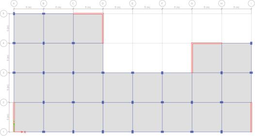
2.1 Salient features and dimensions of the building
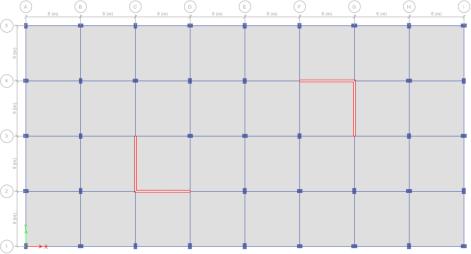
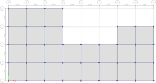
Building was modelled in ETABS for a G+10 storey. The Height is 3m and total height of building is 31.5m. Plan dimensionofbuildingis48m×24m.Buildingisassumedto beinDelhi.
Themodelwasanalyzedforfourdifferentshapes.Rectangle, L, T and U shape plans were used. And shear walls were placedindifferentpositions.Theresultswereobservedfor 42models.SeismiczonesisIV RCCframeisdesignedtobe ductileaspercodeIS13920:1993.
No. Building description
1 Seismiczone IV
2 Importancefactor 1.2
3 Soiltype II
4 Responsereductionfactor 5
5 Slab 150mm
6 Beam 230x500mm
7 Column 400x600mm
8 Shearwall 230mm
9 Deadload 1.5KN/m2
10 Liveload 3KN/m2
11 Gradeofconcrete M30
3. RESULT AND
The maximum displacement at X and Y direction valuesaretakentocalculatetorsionalirregularity coefficient(Ƞt)
Ƞt=��������/��������
Ifthecoefficientisgreaterthan1.2thanthereisan existenceoftorsionalirregularity.
Ifthevalueexceeds1.4than
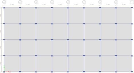
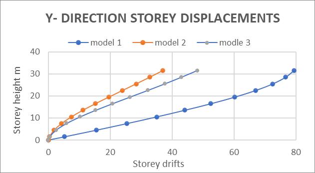
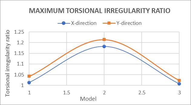
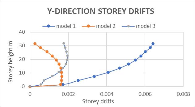
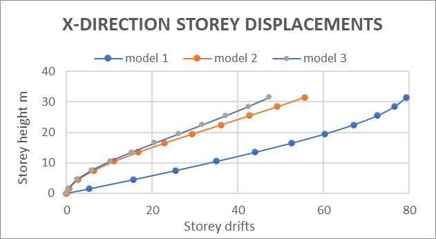
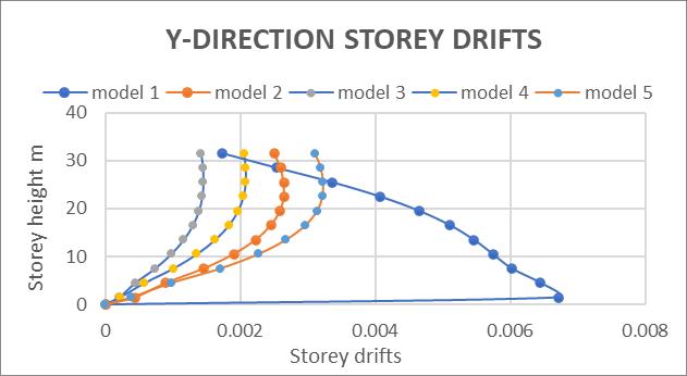
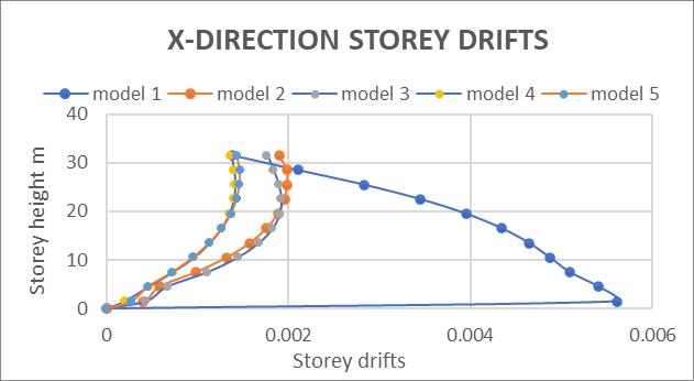
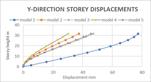
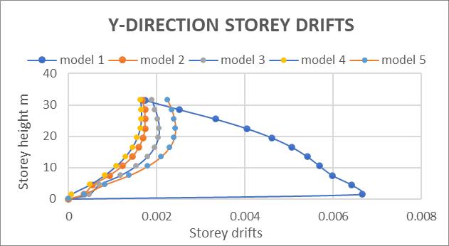
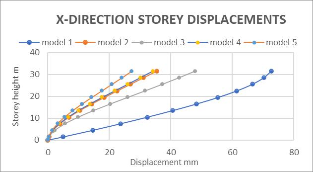
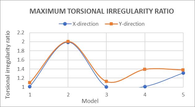
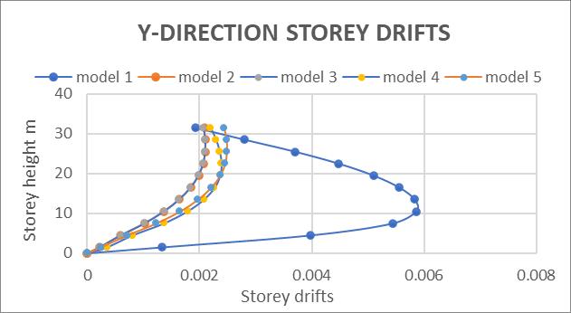
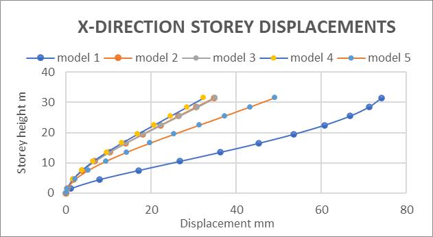
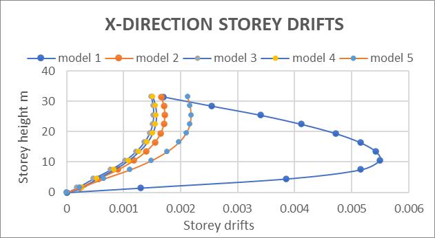
Thebuildingheightis31.5m.Themaximumdisplacements obtainedfromthreemodelsare138mm,50mm,and48mm respectively.Thedisplacementlimitforaheightof31.5mis 63mm (H/500). The maximum story drifts obtained from threemodelsare0.0017,0.0021and0.000162respectively. Theinter-storydriftlimitissetat0.004h.Figure4.5depicts
themaximumtorsionalirregularityratio.Model3performed betterintherectangularshape.
3.2 L
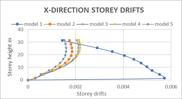
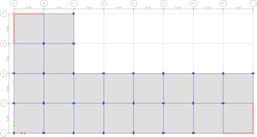
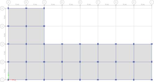
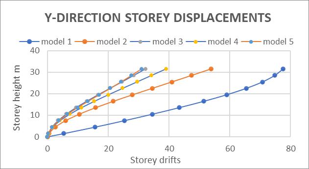
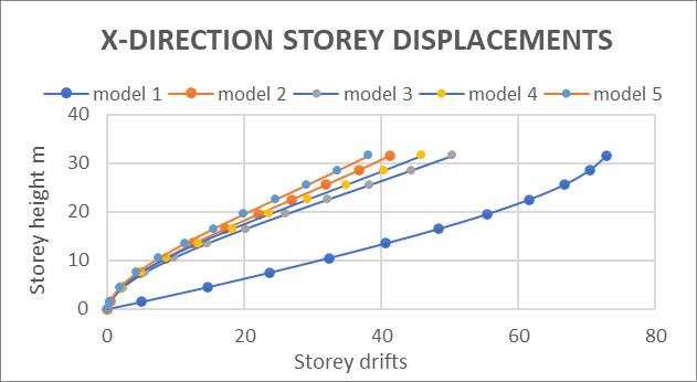
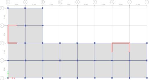
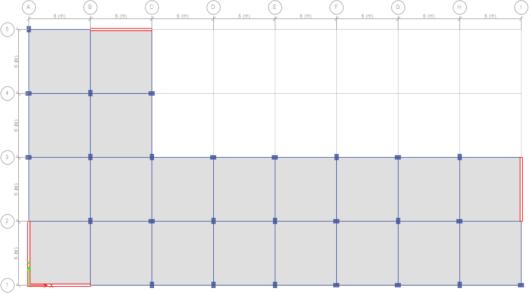
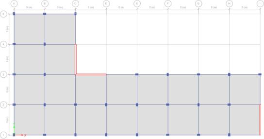
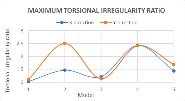
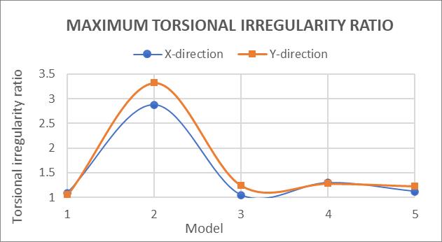
Chart -10:Maximumtorsionalirregularityratio
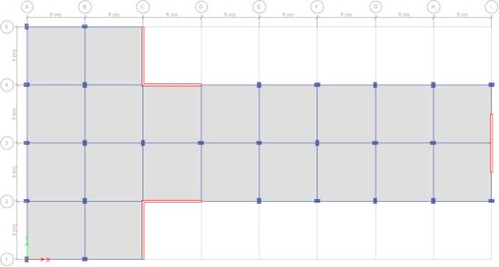

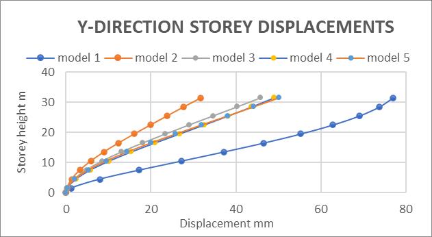
Themaximumdisplacementsobtainedfromfivemodelsare 129mm,53mm,48mm,45mm,and38mm,respectively,fora buildingheightof31.5m.Thedisplacementlimitforaheight of 31.5mis63mm(H/500).Allthemaximumstoreydrifts obtainedfromthefivemodelsarewithinthelimit.Theinterstory drift limit is 0.004h. Figure 4.11(b) depicts the maximum torsional irregularity ratio. Model 3 performed betterintheLshape.Thoughdisplacementsintheshearwall modelsarewithinthelimit,thetorsionalirregularityratioin models 2, 4, and 5 exceeds the limit. As a result, the placementoftheshearwalliscritical.
3.3 T Shape
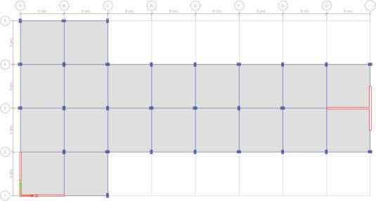
Maximumdisplacementsobtainedfromthefivemodelsare 128mm,37mm,47mm,34mm,and45mm,inthatorder.The displacementlimitforaheightof31.5mis63mm(H/500).All ofthemaximumstoreydriftsobtainedfromthefivemodels arewithinthelimit.Themaximumamountofinter-storydrift is 0.004h. Figure 4.16 depicts the maximum torsional irregularity ratio. The T shape model 3 produced better results. Only the
irregularity ratio exceeds
3.4
Themaximumdisplacementsobtainedfromthefivemodels
are128mm,34mm,45mm,48mm,and50mm,inthatorder. The displacement limit for a height of 31.5m is 63mm (H/500).Allfivemodels'maximumstoreydriftsarewithin the limit. The maximum inter-story drift is 0.004h. Figure 4.22(b)showsthemaximumtorsionalirregularityratio”.The Ushapemodels3,4,and5performedbetter.
the in torsional irregularity ratio increases and decreases dramatically.
4. CONCLUSION
The summary of the key points and conclusions from the analysis of multi-storey buildings with plan and elevation irregularitiesusingresponsespectrummethod:
Plan configurations and elevation irregularities significantly affect the seismic response of multistoreybuildings.
As irregularities increase, so does the inter-story drift response, with lower stories being more affectedthanupperstories.
The increased plan and vertical irregularity of buildingsleadtoincreasedshearforcedemandson vertical resisting components, which can compromisethebuilding'sstability.
Proper placement of shear walls is important for reducingdisplacementandincreasingearthquake resistance.
Irregularitiesinbuildingscannotbefullyaccounted forbycode-requiredloadcombinationprocedures, so designers must carefully study irregular and complexbuildingsinbothdirectionstoensuretheir safety.
Torsional irregularity ratio increases as plan or elevation irregularities grow, leading to higher torsionalmomentsthatmustbetakenintoaccount whendesigningearthquake-resistantstructures.
Implementing earthquake-resistant model proposalsintobuildingcodescanhelpensurethe safetyofmulti-storeybuildingsinseismiczones.
4.1 Scope of future study
ConsiderotherirregularitiesaspertheIScodeand addmoreshapesfortheanalysis.
We can fix the percentage of vertical geometric irregularityandvarythediscontinuityindifferent storey or by increasing the percentage of irregularity.
Obtaining the best optimum position for the placement of shear walls for the various shapes considered.
Since I fixed the building dimensions even after adding shear walls. Which tends to uneconomical design. So, we can alter the size of structural membersbasedontherequirements.
Similarstudiescanbetakenupforbuildingswith infill walls, dampers, bracings and other load resisting structures and results obtained may be compared
REFERENCES
[1] RobertTremblayandLaurePoncet(2005)."Seismic PerformanceofConcentricallyBracedSteelFrames in Multistory Buildings with Mass Irregularity". JournalofStructuralEngineering,Vol.131,2005,pp. 1363-1375.
[2] DeStefano,M.,&Pintucchi,B.(2008).Areviewof researchonseismicbehaviourofirregularbuilding structures since 2002. Bulletin of earthquake Engineering,6(2),285-308.
[3] C.M.RaviKumar,K.S.BabuNarayan,M.H.Prashanth , H.B Manjunatha and D. Venkat Reddy (2012). "Seismic performance evaluation of RC buildings with vertical irregularity". Indian Society of EarthquakeTechnologyDepartmentofEarthquake EngineeringBuildingIITRoorkee,PaperNo.E012
[4] RuchaS.Banginwar,M.R.Vyawahare,P.O.Modani (2012)."Effectofplansconfigurationsontheseismic
Whenshearwallsareintroducedintobuildings,theyplaya significantroleininducingtorsion.Itisaniterativeprocessto eliminate or reduce the torsional irregularity ratio. In the planirregularitysection,wecanseeandcomparetheresults ofvariousmodels.Whentheshearwallpositionischanged, behavior of the structure by response spectrum method”. International Journal of Engineering Research and Applications. (DERA) ISSN: 22489622Vol.2,Issue3.pp.1439-1443
[5] Sachin G. Maske and Dr. P.S. Pajgade (2013) “Torsional Behavior of Asymmetrical Buildings”. International Journal of Modern Engineering Research. Vol.3, Issue.2, March- April. 2013 pp1146-1149
[6] GunayOzmen,KonuralpGirgin,andYavuzDurgun (2014) "Torsional Irregularity in Multi story Structures." International Journal of Advanced Structural Engineering, SPRINGER, DOI 10.1007/s40091,Volume6,2014,pp-121-131
[7] Paradeshi Sameer andN GGore (2016). "Study of Seismic Analysis of Multi storey Symmetrical and Asymmetrical Building." International Research
Journal of Engineering and Technology (IRJET), p-ISSN: 2395-0072, Volume 3, Issue 1, Jan 2016, pp-732-737
[8] AkashRaut,PrabodhPachporandSanketDautkhani (2018)“AnalysisofanIrregularRCMulti-storeyed Building Subjected to Dynamic Loading” - IOP Conference Series: Materials Science and Engineering330(2018)012121
[9] Özbayrak,Ahmet&Altun,Fatih.(2019).Torsional effectofrelationbetweenmassandstiffnesscenter locations and diaphragm characteristics in RC structures.BulletinofEarthquakeEngineering.18. 10.1007/s10518-019-00744-8.
[10] K.VamsiKrishna,k.NagaPoojitha,“Seismicanalysis for vertically geometric irregularity using e-tabs”. InternationalResearchJournalofEngineeringand Technology(ISSN:2395-0056),March2019
[11] Khanal, Bharat, and Hemchandra Chaulagain. "Seismic elastic performance of L-shaped building framesthroughplanirregularities."Structures.Vol. 27.Elsevier,2020.
[12] IS1893.(2016)."Indianseismiccode,Part1.Criteria for Earthquake Resistant Design of Structures, GeneralProvisionsandBuildingsBureauofIndian Standards.