POWER QUALITY AND THD MITIGATION IN ELECTRIC VEHICLE CHARGING STATION BY THE ANN CONTROLLER
Ms. Y.SANDHYA1 , Mr. S RADHA KRISHNA REDDY21PG scholar in the Dept. of Electrical & Electronics Engineering, in Holy Mary Institute of Technology & Science, Bogaram (V), Medchal District, Hyderabad, India.
2Professor in the Dept. of Electrical & Electronics Engineering, in Holy Mary Institute of Technology & Science, Bogaram (V), Medchal District, Hyderabad, India.

Abstract: These EVs have amajor impact onthepowergrid & distribution networks due to the consequences of huge power demand to recharge their batteries. A large number of EV charging station when integrated with the utility grid, it produces harmonics, affect the voltage profile, finally affects the power quality. Artificial Neural Network (ANN) is presented in this study for simple operation and high optimizationapproaches.ANNcontroltechniqueregulatesthe system's THD and enhances charging system optimization, enabling two-way power delivery that is from the grid to vehicle and the vehicle to grid. An ANN-based current controller model that achieves fast-dynamicreactionandthat improves gridcurrent harmonic characteristicsisproposedin this study. In this paper, battery supported transportation systems called electrical vehicles (EV) and the wireless charging topologies are presented.Thetechniquesaremajorly based on current fed dc-dc converter topologies. This paper presents the detailed evaluation of electrical parameters, comparison of various qualitative features of power transfer techniques, IPT for EV application, the control strategies and challenges for EV battery charging.Inthispaper,theimpactof an electric vehicle charging station on the power grid and distribution networks is analyzed in terms of power demand, harmonics, Voltage sag & swelling, and transformer power loss. Also, the mitigation technique for reducingpowerquality disturbances is analyzed in this paper. The system's THD is reduced by the ANN controller being suggested. The parameters are evaluated and the results are presented in
MATLAB/SIMULINK
Keywords: Electrical vehicles (EV), EV charging station, batteries, Artificial Neural Network (ANN), grid, distribution networks
I. INTRODUCTION
At present, worldwide on-road transportation primarily reliesonpetroleum.Thiscausestheemissionofenormous amount of greenhouse gases, thereby making it harder to satisfy stringent environmental regulations [1].Transportationelectrificationenablestheutilizationof energynotonlyfromfossilfuelsbutalsofromvariabledc sources, such as hydropower, solar-PV, and wind power. Electric Vehicle is comparatively new concept in the transportation sector. Due to several benefits i.e. less
environmental pollution, cheaper mode of transportation, use of less petroleum, EV becomes very much attractive now-a-days.Therearemainlythreetypesofelectricvehicle available in world-wide i.e. Plug-in-hybrid electric vehicle (PHEV),Hybridelectricvehicle(HEV)andBatteryelectric vehicle(BEV).Intractionapplications,theelectrificationof railroad'shasbeenfullyachievedinthepastmanyyears. However,therearesomeobviouschallengesforlargescale deployment of electric vehicles (EVs) [2]. Therefore, the mass deployment of EVs was never realized in spite of several government initiatives such as subsidy and tax incentives. The most competitive solution for EV is Li-ion batteries, which has an energy density of about 90100Wh/kg,whereasforgasolineitisabout12000Wh/kg[34].RecharginganEVbatterytakesatleastalotmoretime thanthatrequiredforrefuelinggasolinecars.Therefore,EVs cannotgetreadyimmediatelyifthebatterychargeisover. Charging cables of EV are inconvenient and may lead to tripping, leakage due to aging of cracked old cables, and otheradditionalhazardsespeciallyincoldzones.Wireless chargingisconvenient,safeandreliableduetoelimination ofdirectelectricalcontact.Thepowertransferisunaffected inintimidatingenvironmentsuchassnow,water,dirt,wind, andchemicals.Itprovidesgalvanicisolation.Besidesthese generaladvantages,theWPTtechnologyhasmeritswhich are specific to particular applications. In biomedical implants, for e.g., in heart pump battery recharging, WPT technology is the most practical and convenient [5-6]. Similarly, WPT has found wide acceptance for recharging batteriesofelectronicgadgets,lighting,chemicalplants,and underwater vehicles, etc. due to its flexible usage and the abilitytopreventdamagestothechargingport
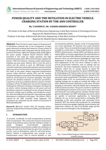
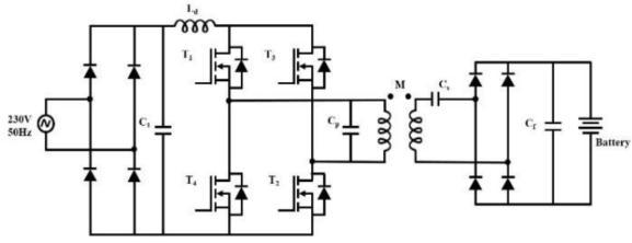
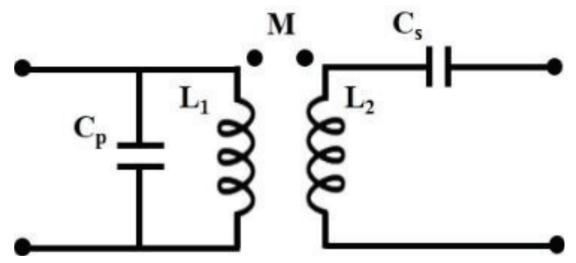
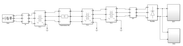
To connect capacitor in primary and secondary coil to compensate the reactive power is it the simple and short methodforimprovementtheresonancefrequency.Basically fourbasictypesofcompensationnetworkspossiblewiththis method i.e. series- series (SS), series-parallel (SP), parallelseries(PS)andparallel-parallel(PP).Forinversion stageascurrentsourceinverter(CSI)thantheprimaryside be connected as parallel connection of resonance compensationisquitecommon.AlsoVSIasinverterLCL[7] and CLCL [8] compensation topologies are also used for improved power factor at inverter output and better performancewithimprovedpowerrange.Thecurrentfed topologieshavebeenmostlyusedinresearchpointbecause ofithasmeritsinIPTcircuitwhencompensationcapacitoris associated in parallel with ttransmitter coil (TC) [9].The current-fedIPTtopologywithparalleltypetanknet-takesa shot at TC and RC circuits. The resonance connection of parallel capacitor it allows the high frequency to occurs throughtransmittercoil.Bethatasitmay,sincetheparallel capacitor,Cpalonegivesthenecessaryreceptivecapacityto approximatelycoupledTC;subsequently,forhigherpower applications, this parallel capacitor encounters higher voltage. This voltage decides the inverter switch voltage rating.Inthisway,thislimitstheuseofcurrent-fedtopology in higher power applications, for example, EV battery charging[10].Themainadvantageofcurrentfedtopologyis lower current stress, short-circuit protection and high reliability. However, a large dc inductor is required, this increasestheefficiencyandpowertransfercapability.The power flow directionisunidirectional orbidirectional. EV Battery Charging technologies have developed many differentmethods.TheDifferentmethodsandcoilairgap distance. The presentation of work is reviews the developmentforinductivepowertransferofelectricvehicle battery charging application, the inductive power transmissionsystemisshowninFig.1.
II. THE STATE OF ART ON INDUCTIVE POWER TRANSFER SYSTEMS
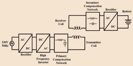
WirelessPowerTransferSystemImplementationofwireless charginginEVapplicationsprovidesremarkableoutcomes. Along with the aforementioned merits, it can reduce the batterystoragerequirementto20%throughopportunistic chargingtechniques[8-9].ForEVs,opportunisticchargingis possiblebyplacingthewirelesschargersindifferentparking areas,fore.g.,home,office,service,shoppingcomplexesand other general parking areas. Also, these chargers can be installedinthetrafficsignalareasforquickrecharging.For rechargingelectricbusesitcanbeinstalledinbusterminals, bus-stops and traffic signals. Three types of WPT TechnologiesInthissectionabriefoverviewandqualitative comparison of all the possible WPT technologies are reportedinTableI.Basedonthisstudy,themosteffective technologyisselectedformediumpower(fractionofkWto severalkW)andmidrangeairgap(about100mm-350mm) applications, which are especially suitable for EV battery charging.
InductiveWPTInductivechargingapplicationforthemost part comprise of an source side power converter, an inductiveinterfacetransformer,andanloadconverter[10]. The interface transformer is distinct along the attractive circuit with the goal that one of the windings can be physicallyevacuated,dispensingwiththerequirementfor ohmic,i.e.,metal-tometal,contactofelectricwires.Insucha transformer, the shape and area of the attractive center material and windings are significant structure decisions. This technology is already implemented in EV charging systems.Thechargingpointofpin(theessentialcoil)ofthe inductively coupled charger is fixed in as it is done in the auxiliary.Theembeddedintothefocalpointoftheauxiliary curl allowed charging of the EV1 with no contacts or connectorsateither6.6kWorat50kW.
CapacitivePowerTransfer
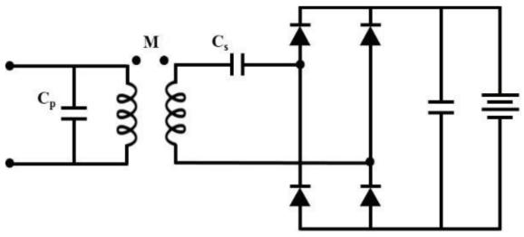
TheWirelesspowertransferbycapacitivethanitsknownas (CPT)technologyisthealternativelywirelesspowertransfer solution.[10].Fig.3showsatypicalCPTsystemfedfroma half bridge current source inverter and the primary /transmitter and secondary/receiver side compensation networksareLCtype.AsshowninFig.3,thepairofcoupling capacitorasconnectacrossinterfacearound.Theoperating principle is same as usual parallel capacitors, where the dielectricmediumisonlyair.InductivecouplingrequiresLC compensation networks. This technology finds suitable applicationsinlowpowerlevelsuchasbiomedicalimplants, orinchargingofspaceconfinedsystemssuchasrobotsor mobiledevices[11],[12],[3].Itsdesignflexibilityandlow costmakeitidealforpowerdeliveryinreconfigurableand movingsystems,suchasrobotarms,latches,andin-trackmoving systems [11]. However, owing to lower power density, the CPT technology is not preferred for higher powerapplicationssuchasEVcharging[7]
BatterySwappingSystemItispossibletorecognizeinthe previouslinesoneofthegreatestdisadvantagesofEVs:the rechargingprocedurecantakeuptohourstobecompleted. Analternativeapproachinordertospeedupthe“refueling” iscalled“batteryswap”.
Aphysicalsubstitutionofthedischargedadedicatedstation [4].Thisactioncaneliminatethedelayrelatedtothefully charged.BatterySwappingintroducesdifferentadvantages to the electric vehicle sector. The main ones are: x Fast batteryswappingoperation,ittakeslessthanfiveminutes;x Problemsoflimiteddrivingrangearesolvedwherebattery switchstationsareavailable;xDriversdonotgetoutthecar duringthereplacementofthebattery;Driversdonotown the battery and costs related to its management are transferredtotheservices,enhancingtheevolutiontowards smartgrids[9].However,alsoseveredrawbacksshouldbe considered. The major issue is the huge costs of the componentsneededtoobtainanefficientswitchingstation. Moreover,inordertoperformbatteryswapitisnecessaryto havesuitablydesignedcars
Wired System and Wireless System Comparison Electric vehicles were reintroduced in the last few decades as a reactiontotheenvironmentalsensibilitythatwe,ashumans, developed [11]. Moreover, the volatility of fuel prices and reductionofelectricitybillsmadeinvestmentsinthisfield moreinteresting.Atthebeginning,designershadtofinda way to recharge the on-board batteries in a manner that couldbecomparabletothewaywealreadyfillthetanksof traditionalcarsorsomehowevenbetter.Thatwasandstillis achallengingtargetsinceatpresent,noEVstoragecanbe chargedasquicklyasanyinternalcombustionvehicletank filling.Concerningtechnical issues,theycan bediscussed: Electricaldangerrepresentedbyinsulationbreakdowndue toagingofthecomponent,fulgurationisarealpossibility; Thesamesecurityisendangeredalsobyexternaleventsthat could put at stake safety of the charging operation; Interoperability is not ensured in most of the cases, car manufacturersdevelopedproprietaryplugs;Theelectrical pins must be thoroughly cleaned from dust and debris in order to perform an optimal connection between car and rechargingtower.Ontheotherhand,fromanamenitypoint ofviewitcanbesaid:Thecableisnotaesthetic;Itrequires some manual actions that make it not very functional. Resonancepowertransferuptoapproximately10meterand operating frequency is in the MHz range. However, for several kW power transfer with air gap suitable for EV applications,thisRAPTtechnologyisessentiallysameasIPT technology.
III. INDUCTIVE POWER TRANSFER SYSTEM POWER CONVERTER
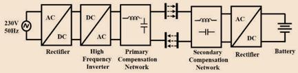
ForwirelesschargingsystemsofEVs,powerelectronicsplay animportantroleformaximumsystemefficiencyatpower conversion stage. This is very crucial for primary stage of wireless charging of EVs. Therefore, in power conversion stage,halfbridgeorfullbridgeispreferred.Becauseofthe alternating current in the magnetic coupling between the loops,inputvoltagesovertheessentialandtheoptionalside areexchanging.Twocontrolconvertersarerequired,onein theessentialsideandtheotheroneintheoptionalside.In the essential side, a twofold stage is commonly utilized, consistingofanAC-DCandaDC-AC(thisDC-ACistheone featuredinFig.3andFig.4).Theobjectiveofthistwofold stageistobuildthepowertransferfrom50Hz(or60Hz)of thenetworktokHzoftheIPT.IntheauxiliarysideanAC/DC stage is required. The recent research for the most part, centersaroundtheessentialDCsegmentandtheauxiliary DC segment. The increase in reactive current losses increasestheVAratingsoftheinputsourceasmoreactive power transfer to the load is required. To avoid this, compensation networks are used in parallel and series configuration.
A. PrimarySideDC-AC
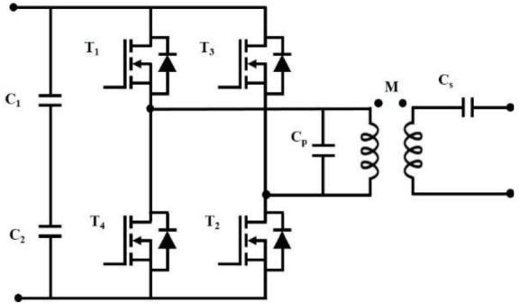
Various arrangements be explored, about the essential conversion is DC/AC organize and the optional AC/DC arrange.Totheextenttheauxiliaryplaneisconcerned,two conceivableoutcomeshavebeenpredominantlyabusedto interfacetheoptionalsourcesidetotheloadsidebattery: eitheranaloofrectifierinadditiontoaDC-DCconverterora functioningAC-DCarrange.[7].Generally,thehalfbridgeor fullbridgeconvertertopologyforprimarysidetotransmit thepowerqualitycapabilityispreferred.Fullbridgecurrent fedconverterisusedinthiswork,withthisahighervoltage transfercapabilityispossible.
B.SecondarySideAC-DC:
In the optional side, an AC-DC stage is required to change over the AC voltage emerging from the inductive power moveintoaDCvoltagevaluabletosupplythebattery.Asper issues of proficiency and controllability, two elective arrangementareusablefortheAC-DCorganize:adetached rectifierorafunctioningrectifier.AC/DCconverterisused to correct the power factor at the utility to meet the load total harmonic distortion (THD). The primary side, a constantDCvoltageisconvertedtohighfrequencyvoltage pulses with adjustable duty cycle which is fed to the compensation network. After this, different compensation networksareuseddependingonapplication.Foroptimum powertransfer,loadimpedanceneedstobematchedwith the source impedance. The passive rectifier regularly comprises of a customary four-diode connect which essentially corrects the AC sign emerging from the attractivelycoupledcurls.ThedeliveredDCvoltagemustbe preparedsoastosupplythebatterypoweredbattery.Along these lines, a DC-DC middle of the road stage is required betweenthedetachedrectifierandthebattery,withthegoal that the charging current can be appropriately controlled. ThissolutionisshowninFig.5.
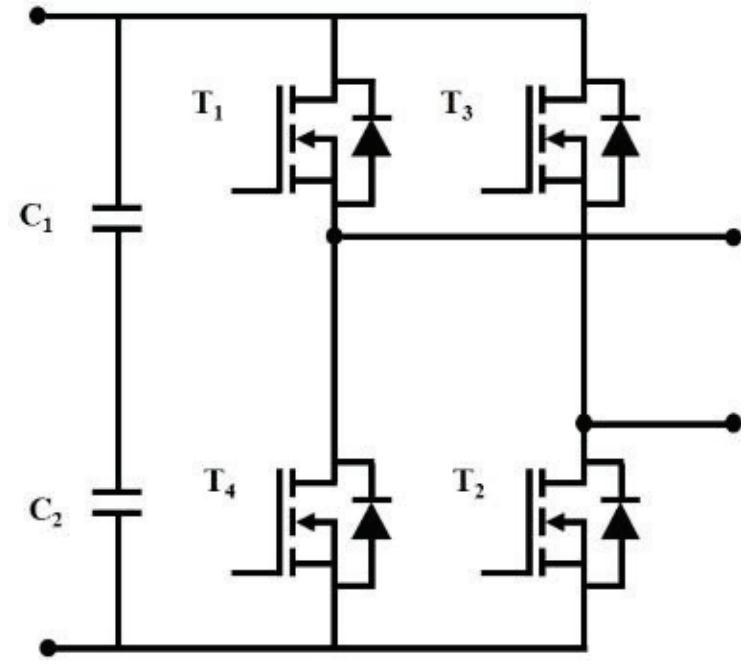
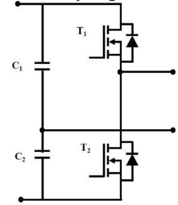
the output voltage of the neutral point between two capacitors is normally unbalanced during the switching process of two switches. Another limitation of the halfbridgetopologyisthattheconvertercanonlygenerate ac output with the amplitude of ±vdc/2, which limits its applicationonlyinlowerpower.Therefore,inpractice,Hbridgeconvertersarepreferableinmostofapplications.The voltagesourceinvertertopologiesareshowninFig.6
B. ClassificationsBasedonPowerConverter
Topologies The input power of IPT inverter is usually suppliedfromadcsource,suchasPVmodulesorarectified ac grid. The purpose of this converter is to feed high frequencyac to primaryresonant tank,and maintainload power to desired level. A number of IPT power converter topologiesarereportedinliterature,andtheseareclassified asfollows.1)VoltageSourceInverterTopologies:However,
2)CurrentSourceInverterTopologies:
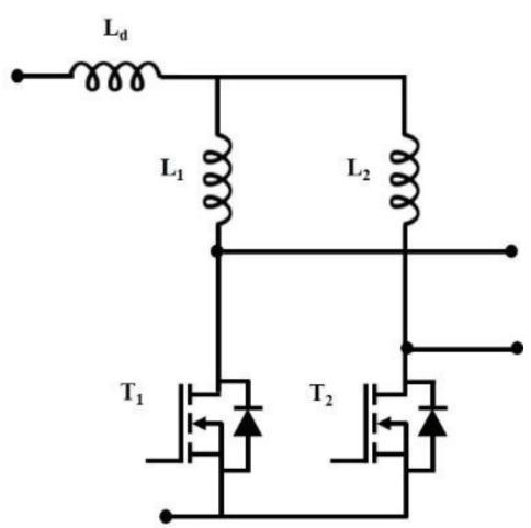
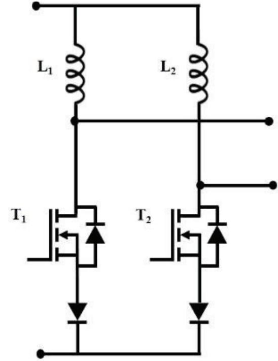
Occasionally,currentsourceinverter(CSI)isalsousedinIPT systems[5-7].Fig.7showstheexistingIPTsystemsfedfrom acurrent-fedpush-pullinverter,wherethetransmittercoil tanknetworkisparallelLCtype.Followingmeritsofthese systemsarereportedinliterature.Theevaluatedparameters forinductivepowertransmission.
IV. INDUCTIVE POWER TRANSFER MODELLING CURRENT-FED CONVERTER
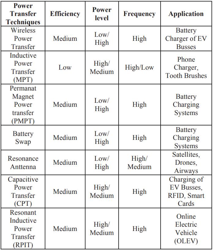
ResonantAntennaePowerTransfer(RAPT)isalsopioneered andpatentedbyNikolaTesla,andhasrecentlybeenstudied byMIT[13]andIntel.Thefundamentaloperatingprinciple ofthistechnologyissimilartoIPT.Theairgaplengthcanbe much longer than IPT system due to use of high-quality factorcoilsandhighfrequencyofoperation.Thepossibleat distances up to approximately 10meters and operating frequency is in the MHz range. However, for several kW powertransferwithairgapsuitableforEVapplications,this RAPT technology is essentially same as IPT technology. Evaluated power transfer capability in this technique is observed for a VA rating, power input from the source is transferredtotheload.Thereactivecurrentincreasesdueto losses, to avoid this, high compensation networks are connectedtocanceltheleakageinductance.Atypicalcurrent fed converter for WPT application is shown in Fig. 8, for lower circulating current, parallel resonance is employed. Parallel capacitors form the low impedance path for
circulatingcurrentpath.Voltagestressincreaseswithpower transfer.
GeneralResonanceCompensationTopologies
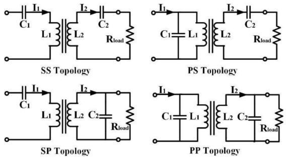
In a typical IPT system for EVs, there are four basic topologies:SS-connected,SP-connected,PP-connectedand PS-connected circuits are shown in Fig. 9 [14]. The advantages are high power transfer with quality power supply, minimized VA rating, constant voltage, constant current depending upon load application, high efficiency, bifurcationtolerance,highmisalignmenttolerance.
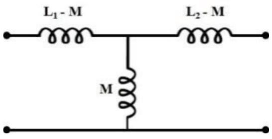
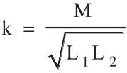
Usingamutual-inductancemodel,theequivalentcircuitof theresonantinductancesisshowninFig.10,whereMisthe mutualinductancebetweenthetransmittingandreceiving coilsorpads.
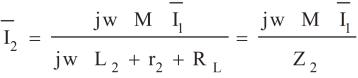
Modeling of Resonance Inductive WPT The essential Equivalent circuit outline for P-S Compensation Currentbolsteredreverberationinductiveremoteforcetransmission is appeared in Fig. 11. The transmission of intensity yield proficiencycanbedetermined.
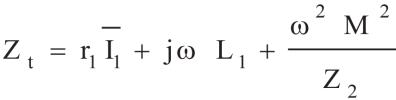
Z2isequivalentimpedancereceivingside,Equation(4)in (1)
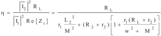
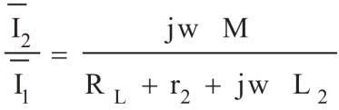
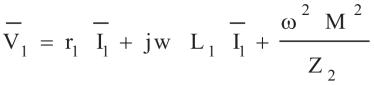
TotalImpedance(Zt)fromtransmittingcoil
characteristics.InP-Sconfiguration,themainadvantagesof theimpedancetransferredarehighefficiency,highpower factor at relatively low mutual inductance, large range of variationofload,butthepowerfactorisnotatunity,current fed input avoids any instantaneous changes in voltage, primary capacitor depends on load and coupling factor, inverter device voltage is higher, it does not allow zero coupling, but in voltage source it allows. The evaluated parameters are simulated in MATLAB/Simulink and the performance of transmitter coil for inductive power transmission.
V. MATHEMATICAL MODELING
Asanon-linearload,EVchargerproducesharmonics,low voltageprofileandpowerlossindistributiontransformer.In Bangladesh,forEVcharginglevel2typeACchargingscheme isusedwheremaximumcurrentratingis16Aandmaximum power rating is 3.3 kW. Most of the electric vehicles have powerrangesfrom0.5kWto1kWandallofthemusesingle phase240V,50Hzsupplysystem.Inthissection,wehave developed mathematical modeling for harmonics, voltage profileandtransformeroverloadingduetoEVcharging.
PowerDemandElectricVehiclebatterytakeschargefrom thepowerdistributionsystem.Theincreasedpowerdemand affectsthestabilityofthesystemduetonon-linearity.The powerdemandbyanEVcanbeexpressedasinEquation(1).
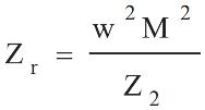
ZrReflectedimpedance
Equation(2)and(6)
(since:k=0.1to0.5range)
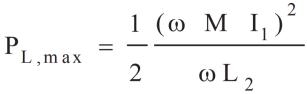
Inductive power transfer efficiency, maximum power transferisgivenequation(9)and(10)
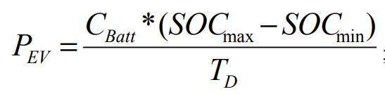
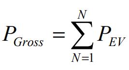
Where CBatt is the battery capacity, TD is the duration of charging.BatterySOCisafactorwhethertheEVtakeshigh orsmallpower.ThegrosspowerdemandoftheEVsisthe summation of individual power demand of all EVs which likelysignifiesasinEquation(2).
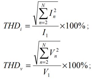
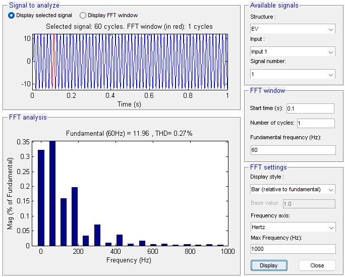
HarmonicsTheriseinhighfrequencycomponentsofvoltage and current with compared to fundamental frequency is defined as harmonics. Harmonics distorts the voltage & currentwaveformsandtherebyaffectingpowerquality.It can be measured by total harmonic distortion (THD) of current&voltage.
Here by we observed that from the compensation of P-S compute the electrical components for pursue of mutual inductance value that have been give performance of the
Equation (3) & (4) express the Total Harmonic Distortion (THD) for current and voltage respectively [6]. For slow
charging THDi, THDv will be less than the fast charging. Thus, the EV with low SOC will have a great chance to produceharmonics.
Voltageprofile.
Thelowvoltageprofilebecomesathreateningissueinduced byEVcharging.Voltagestabilityreferstotheabilitythatthe power network being stable after the sudden increase or decreaseintheloads.EVloadstakelargeamountofpower at a very short duration. Thus, voltage profile will be degradedandgridwillbeunstable.
Transformerperformance
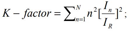
Mass deployment of EVs creates an additional stress on distribution transformers and their life cycles. Another problemisthat,theEVchargingrateshouldbelimitedper day and charging stations should keep far away from transformer for reducing power loss. Harmonic current is responsibleforoccurringloadlossesintransformerwhereas harmonicvoltageincursnoloadloss.Duetotheseharmonic losses, heating is increased relative to the pure sinusoidal wave.Thisharmonicwithstandcapabilitycanbemeasured byafactorcalledk-factor.
(oroutputsa1),otherwiseitstaysquiet(outputsa0).The outputisthenfedintoalltheneuronsitisconnectedto.
ARCHITECTURE
Thisareaofneuralnetworkingisthe"fuzziest"in termsofadefinitesetofrulestoabideby.Therearemany typesofnetworks-rangingfromsimpleBooleannetworks (perceptrons), to complex self-organizing networks (Kohonennetworks),tonetworksmodelingthermodynamic properties (Boltzmann machines)! There is, though, standardnetworkarchitecture.
InisthecurrentrelatedtonthharmonicandIRistherated loadcurrent.Thepresenceofharmonicscausesoverheating inthetransformer.Thus,thetransformershouldbeselected according to the withstand capability at higher harmonic currentfornon-linearloading[7].
THE NEURON
Although it has been proposed that there are anythingbetween50and500differenttypesofneuronsin ourbrain,theyaremostlyjustspecializedcellsbasedupon thebasicneuron.Thebasicneuronconsistsofsynapses,the soma, the axon and dendrites. Synapses are connections between neurons - they are not physical connections, but miniscule gaps that allow electric signals to jump across from neuron to neuron. These electrical signals are then passedacrosstothesomawhichperformssomeoperation andsendsoutitsownelectricalsignaltotheaxon.Theaxon thendistributesthissignaltodendrites.Dendritescarrythe signalsouttothevarioussynapses,andthecyclerepeats.
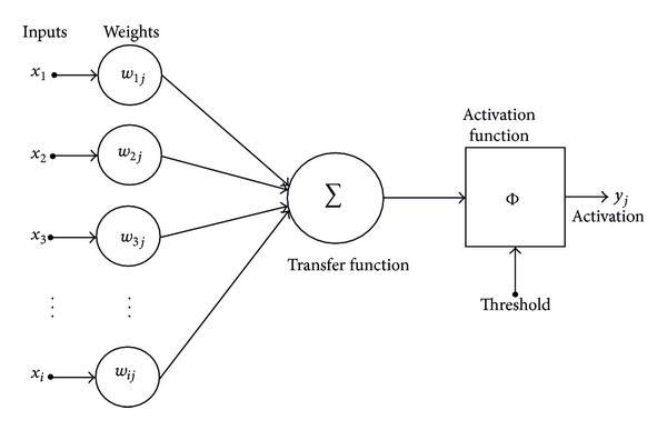
Just as there is a basic biological neuron, there is basicartificialneuron.Eachneuronhasacertainnumberof inputs,eachofwhichhavea weightassignedtothem.The weights simply are an indication of how 'important' the incomingsignalforthatinputis.Thenetvalueoftheneuron isthencalculated-thenetissimplytheweightedsum,the sumofalltheinputsmultipliedbytheirspecificweight.
Each neuron has its own unique threshold value, anditthenetisgreaterthanthethreshold,theneuronfires
ArchitectureofANN
Thenetworkconsistsofseveral"layers"ofneurons, aninputlayer,hiddenlayers,andoutputlayers.Inputlayers take the input and distribute it to the hidden layers (socalled hidden because the user cannot see the inputs or outputs for those layers). These hidden layers do all the necessarycomputationandoutputtheresultstotheoutput layer,which(surprisingly)outputsthedatatotheuser.Now, toavoidconfusion,Iwillnotexplorethearchitecturetopic further. To read more about different neural nets, see the Generation5essays.
Even after discussing neurons, learning and architecturewearestillunsureaboutwhatexactlyneural networksdo!
THE FUNCTION OF ANNS
Neuralnetworksaredesignedtoworkwithpatterns - they can be classified as pattern classifiers or pattern associators. The networks can takes a vector (series of numbers),thenclassifythevector.
Forexample,myONRprogramtakesanimageofa number and outputs the number itself. Or my PDA32 programtakesacoordinateandcanclassifyitaseitherclass
A or class B (classes are determined by learning from examples provided). More practical uses can be seen in military radars where radar returns can be classified as enemyvehiclesortrees(readmoreintheApplicationsinthe Militaryessay).
Pattern associators take one vector and output another.Forexample,myHIRprogramtakesa'dirty'image andoutputstheimagethatrepresentstheoneclosesttothe oneithaslearnt.
Again,atamorepracticallevel,associativenetworks can be used in more complex applications such as signature/face/fingerprintrecognition. VI.
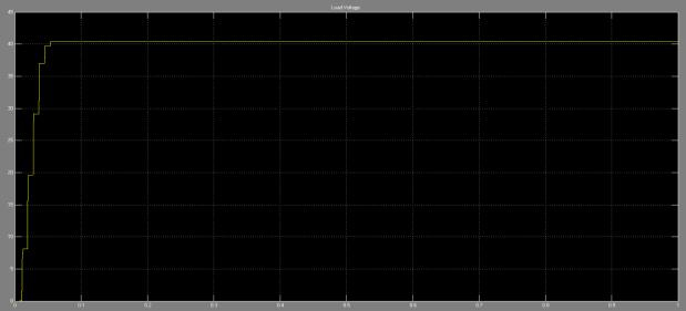
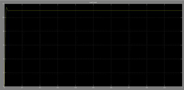
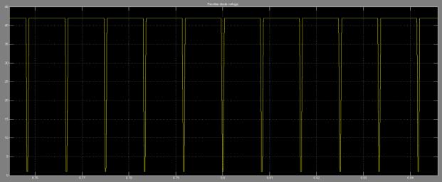
RESULTS
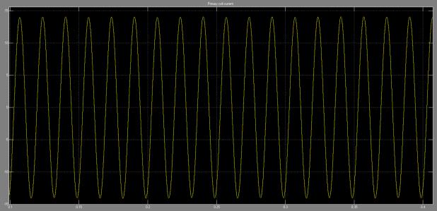
(c) Primarycoilcurrent.
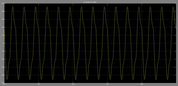
(a) Secondarycoilvoltage.
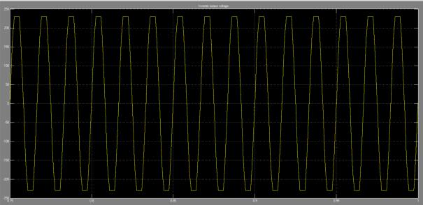
(a) Inverteroutputvoltage.
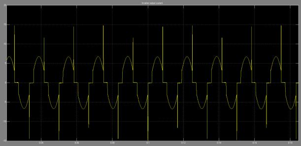
(b) Inverteroutputcurrent.
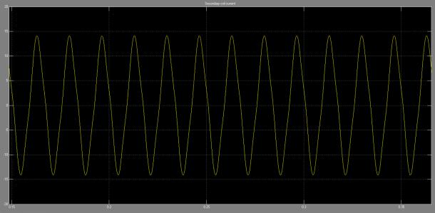
(b)Secondarycoilcurrent
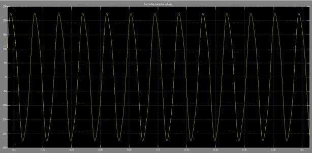
(C)Secondarycapacitorvoltage
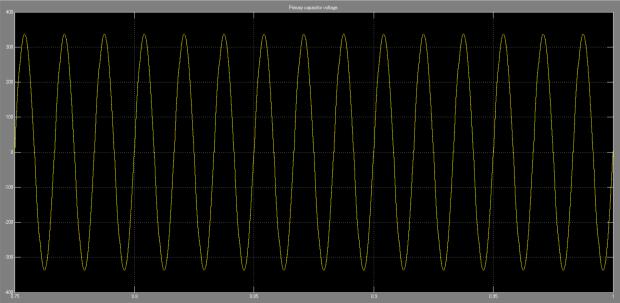
(c)Primarycapacitorvoltage.
CONCLUSIONS
Thewirelesspowertransferforelectricalvehiclecharging techniques is presented in this paper and a comparison amongalltheexistingmethodsintermsofefficiency,power level,frequency,andapplicationareshown.Theelectrical parametersforinductivepowertransmissionareevaluated and the performance is verified in Matlab/Simulink. As maximumEVsarechargedatresidentialconnectiondueto the lack of charging stations, the power sector has been failed to earn the profit from this sector. However, due to somereasonsEVs penetrationmakespowersystemmore vulnerable and hampers power quality. In this paper, the power quality issues like harmonics, voltage fluctuation, transformer power losses are analyzed using MATLAB Simulink.ANNcontroltechniqueregulatesthesystem'sTHD andenhanceschargingsystemoptimization,enablingtwowaypowerdeliverythatisfromthegridtovehicleandthe vehicletogrid.AnANN-basedcurrentcontrollermodelthat achieves fast-dynamic reaction and that improves grid currentharmoniccharacteristicsisproposedinthisstudy. AlthoughtheEVshaveseveralbenefitsaslikestabilizingthe gridatunderloadedcondition,lowerGHGemissionbutthe power quality issues should regulate properly for sustainabledevelopmentinthepowersector.Thecurrent fed topology for inductive power transfer in WPT is compatible.
REFERENCES
[1] G. A. Covic, and J. T. Boys, "Inductive power transfer," ProceedingsoftheIEEE,vol.101,no.6,pp.1276,1289,June 2013.
[2]A.Kurs,A.Karalis,R.Moffatt,J.D.Joannopoulos,P.Fisher, and M. Soljacic, "Wireless power transfer via strongly coupled magnetic resonances," Science, Vol. 317, 83-86, 2007.
[3]F.Musavi,andW.Eberle,"Overviewofwirelesspower transfertechnologiesforelectricvehiclebatterycharging," PowerElectronics,IET,vol.7,no.1,pp.60,66,January201, vol.61,no.5,pp.2307,2315,May2014.
[4]A.KhalighandS.Dusmez,"ComprehensiveTopological AnalysisofConductiveandInductiveChargingSolutionsfor Plug-InElectricVehicles,"inIEEETransactionsonVehicular Technology,vol.61,no.8,pp.3475-3489,Oct.2012.
[5] D. Patil, M. Ditsworth, J. Pacheco and W. Cai, "A magneticallyenhancedwirelesspowertransfersystemfor compensation of misalignment in mobile charging platforms,"IEEEECCE,2015,pp.1286-1293.
[6]C.J.Kaufman,RockyMountainResearchLab.,Boulder, CO,privatecommunication,May1995.
[7] Y. Yorozu, M. Hirano, K. Oka, and Y. Tagawa, “Electron spectroscopystudiesonmagneto-opticalmediaandplastic substrate interfaces(Translation Journals style),” IEEE Transl.J.Magn.Jpn.,vol.2,Aug.1987,pp.740–741[Dig.9th Annu.Conf.MagneticsJapan,1982,p.301].
[8]K.Aditya;S.Williamson,"AReviewofOptimalConditions for Achieving Maximum Power Output and Maximum Efficiency for a Series-Series Resonant Inductive Link," in IEEE Transactions on Transportation Electrification , vol. no.99,pp.1-1.
[9]DevendraPatil,MarcoSirico,LeiGu,BabakFahimiPatil, M.Sirico,L.GuandB.Fahimi,"Maximumefficiencytracking inwirelesspowertransferforbatterycharger:Phaseshift and frequency control”, Proc. IEEE Energy Conversion Congress and Exposition (ECCE), 18- 22 Sept. 2016, Milwaukee,WI,USA.
[10]B.ManguandB.G.Fernandes,“Multi-InputTransformer Coupled DC-DC converter for PV-Wind based Stand-Alone Single Phase Power Generating System,” IEEE Energy ConversionCongressandExposition,ECCE’2014,Pittsburgh, Pennsylvania,USA,Sept.2014.
[11]SusheelaandP.SatishKumar“AnalysisandComparison of Various Pulse Width Modulation Strategies for Hybrid Inverter with Reduced Number of Components,” InternationalJournalofInventionsinEngineering&Science Technology(IJIEST),vol.no.3,pp.12-26,JanDec2017.

[12] Pradipta Patra, Susovon Samanta, Amit Patra, Souvik Chattopadhyay, “A Novel Control Technique for SingleInductor Multiple-Output DCDC Buck Converters”, IEEE InternationalConferenceonIndustrialTechnology,Mumbai, India,15-17Dec.2006.
[13] Suvendu Samanta, Akshay Kumar Rathore, Sanjib Kumar Sahoo, “Current-fed full-bridge and half-bridge topologieswithCCL transmitterandLCreceivertanksfor wirelessinductivepowertransferapplication”,IEEERegion 10Conference(TENCON),Singapore,22-25Nov.2016.
[14] Vaka Ravikiran, Ritesh Kumar Keshri, Manuele Bertoluzzo, “Efficient Wireless Charging of Batteries With Controlled Temperature and Asymmetrical Coil Coupling” IEEEInternationalConferenceonPowerElectronics,Drives andEnergySystems(PEDES).
Authors Details:
Ms. Y.SANDHYA received the DiplomainElectricalandElectronics Engineering from Sudheer Reddy Engineering College Keshapur, Nizamabad, Telangana, India, and received B.Tech degree in EEE from KakathiyaInstituteofTechnologyand Science, Manikbandar, Nizamabad, Telangana, India from JNTUH University. And studying M.Tech in Power Electronics at Holy Mary Institute of Technology and Science, Bogaram, Medchal, Hyderabad, Telangana, India, in the Dept. of electrical and electronics engineering.
Mr. S RADHA KRISHNA REDDY receivedtheB.Tech.inElectricaland ElectronicsEngineering fromMITS Engineering College, Andhra Pradesh,IndiaandM.Tech.inPower Electronics from S.K University, in 2007.Hehas16.6yearsofteaching experience,Currentlyworkingasa ProfessorofDept.ofElectrical&ElectronicsEngineeringat HolyMaryInstituteofTechnologyandScience,Hyderabad, IndiaandPursuingPhDJNTUHyderabad.HePublished48 researchPapers.HisresearchinterestsareComputer-aided powersystemanalysisandmodelling,wideareamonitoring protectionandcontrol,PowerElectronics,FACTSetc.,