Condition monitoring of screw compressors and induction motors in a food processing industry
Rituraj Shashikant Patil1, A. M. Qureshi21M-Tech student, Department of Mechanical Engineering, KIT’s college of engineering, Kolhapur.
2Assistant. Professor, Department of Mechanical Engineering, KIT’s college of engineering, Kolhapur.
Abstract - In this paper, we measured the vibration level of various critical machinery in the food processing industry. Vibration analysis is an effective tool for detecting and diagnosingmachine andequipment faults inthe early stages. Maximum research found that a periodic measurement program detected several potential failures before a breakdown. Screw compressors and induction motors are widely used in the food processing industry for refrigeration. As these types of machinery must run for 24 hours in a dairy/food processing industry and most food items are perishable, breakdown maintenance could be more costeffective Aperiodicvibrationmonitoringsystemisrequiredto detect critical parts' failure. So, an attempt is made for fault detectioninearlierstagestoreducebreakdownmaintenance
Vibration severity as per ISO 10816 is measured in terms of Vr.m.s. (mm/sec) using SKF Microlog Analyzer CMXA 75 The collected data was then processed and analyzed, and corrective actions were taken according to the vibration severity
Key Words: vibration measurement, screw compressor, condition monitoring, induction motor, velocity measurement
1. INTRODUCTION
Inthefoodprocessingindustry,varioustypesofmachinery arepresent.Themajorityof thesemachineshaverotating parts.Machinesmustperformaccordingtotheirdesigned specificationsandinstalledcapacityforanindustrialplantto have high production rates. The machine must be in good working condition to ensure no significant downtime. Machinery condition monitoring is concerned with the maintenanceofthesemachinesbasedontheircurrentand previousconditions.Todeterminethemachine'scondition, sensorsareinstalledarounditsothatrelevantinformation aboutthemachine'sconditioncanbecollectedandanalyzed. Decisionsaremadeabouttheappropriatemaintenanceor corrective actions to be taken so that the machine can performasintended.
Machinesgenerateinformationorsignalsduringoperation through the noise, vibration, temperature, lubricating oil condition,qualityandquantityofmotorcurrentdrawn,and so on. These machine signals are obtained by installing transducerstomeasurethe mechanical parameters of the machine. The signals received in this manner are usually
analog and are always present. An analog-to-digital converters convert the signals into the digital domain to generate meaningful information. Software is available to efficiently store and handle large amounts of digital data collected from machines. This data is then used in the algorithms designed to detect machine faults. Once a machinefaulthasbeenidentified,correctivemeasurescan beimplementedtoensurethatthemachinehasalonguseful lifeandthattheplantismoreproductive.
1.1 vibration monitoring
Vibration analysis is the most well-known conditionmonitoringtechnologyforrotatingequipment.Thetypeof sensor used is determined by the frequency range that is beingmonitored:
Position transducers for thelow-frequency range,Velocity sensorsinthemiddle-frequencyrange,Accelerometersinthe high-frequency range, and SEE sensors (Spectral Emitted Energy)forveryhighfrequencies(acousticvibrations)
The vibration monitoring method can detect the following defects:misalignment,eccentricity,crackedshaft,bowedand bent shaft, unbalancedshaft, looseness, defects in bearing, gearfaults,etc.
Itisa parameterthatgivesthebestinformationaboutthe healthcondition of the machineand helps to diagnose the problems of the machine. The vibration parameter has a definiterelationshipwithtypesofmechanicalfaultwhichare typical characteristics. Advances in instrumentation have mademeasurementandanalysiseasyandsimple.About70% of the machinery faults can be detected using vibration monitoring.
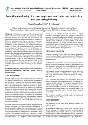
The vibrations must be measured axially, vertically, and horizontallyasshowninFig-3.
2. METHODOLOGY
The objectives of this study were achieved through the followingsteps:
Westudiedtherefrigerationsysteminthefoodprocessing (dairy) industry. The refrigeration system is designed to handle 15 lakh liters of milk daily. It is a fully automated systemusingPLC-basedautomationandSCADA.Thesystem

consists of the following elements: Screw compressors, evaporativecondensers,economizerstoincreaseefficiency, expansionvalves,andvariousevaporatorssuchasplateheat exchangers(PHE)chillersandair-coolingunitsfordifferent applications. The primary function of the refrigeration sectionistoprovidechilledwaterforvariousprocessesin the dairy and maintain the temperature of different cold roomspresentaccordingtothenorms.Thesystemoperates atthreedifferentevaporationtemperatures,whichare-2°C,5°C,and
30°C
Compressortype:Screwcompressor
Allowablepressure:28bar
Maximumspeed:3600rpm
Refrigerantused:Anhydrousammonia(R717)
Motortype:3-phaseinductionmotor
MotorKW:315
Maximumspeed:2985rpm
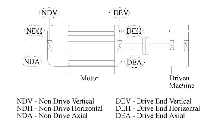
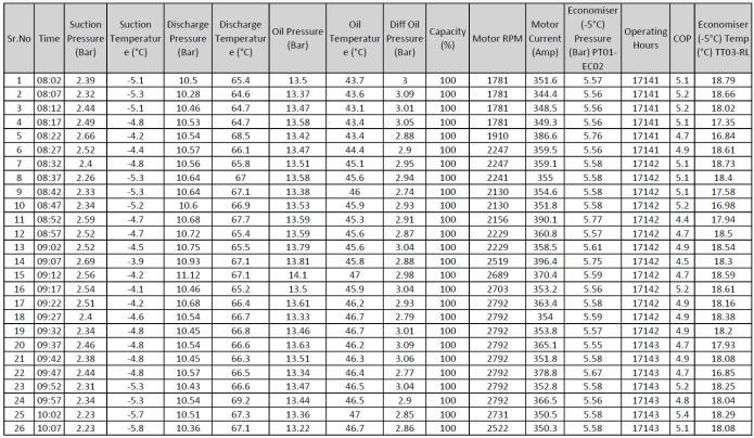
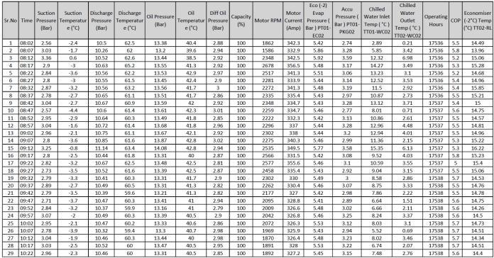
Variousoperatingparameterssuchassuctionpressureand temperature, discharge pressure and temperature, oil pressure and temperature, oil filter pressure, compressor rpm, and motor current were observed for more than a monthandrecorded.Anexampleofthesameisgivenbelow:
Suction pressure: 2.56 bar, suction temperature: -2.4 °C, dischargepressure:10.5bar,dischargetemperature:62.5°C, oil pressure: 13.38 bar, oil temperature: 40.4 °C, capacity: 100%,motorspeed:1862rpm,motorcurrent:342.3amp.
Vibrations were measured per ISO standards using SKF Microlog Analyzer CMXA 75 horizontally, vertically, and axiallyonthedrivingend(DE)andnon-drivingend(NDE)in terms of r.m.s. Velocity and compared with the Vibration severitychart.Aftercomparingandanalyzingthevibration severityvalues,correctiveactionsweretakenaccordingto the findings during the initial vibration measurement, describedindetailintheresultssection.
We measured the vibration severity again after taking the correctiveactions.Thisisnecessarytoconfirmthatthefault diagnosisandcorrectiveactionswetookwerecorrectand thatnootherfaultsarepresentinthemachine.
3. RESULTS AND DISCUSSION
3.1 Measurement of vibration according to ISO 10816
According to ISO 10816, the system's root mean square (r.m.s.) velocity under consideration was measured. The velocitywasmeasuredvertically,horizontally,andaxiallyat thedrivingend(DE)andnon-drivingend(NDE)
ThesystemunderconsiderationfallsunderClassIII,i.e.,large prime movers and other large machinery with rotating masses mounted on rigid foundations. The results of the measurementarestatedbelow:
(mm/s)
Table -4: MeasuredvelocityofammoniacompressorNo.4
AmmoniacompressorNo.5:
Vr.m.s.(mm/s)
Table -5: MeasuredvelocityofammoniacompressorNo.5
AmmoniacompressorNo.6:
Vr.m.s.(mm/s)
Table -6: MeasuredvelocityofammoniacompressorNo.5
Measuredvelocityof
MeasuredvelocityofammoniacompressorNo.2
Analysis of measured data and corrective actions are taken:
Comparedtherecordedvalueswiththevibrationseverity chartperISO10816(Fig-4).
The vibration severity values for ammonia compressors No.1,3,4,5 and 6 were within acceptable levels. All the operating parameters were within the limit; no abnormal soundswerepresentwhileoperatingatvariousloads.
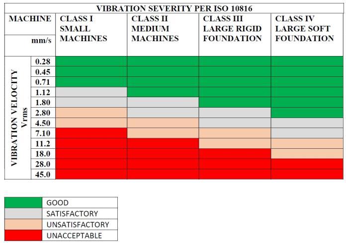
For ammonia compressor No. 2, the measured axial and vertical velocity values (axial: 7.2 mm/s, vertical: 5.70 mm/s)atthemotor’sdrivingendwereintheUnsatisfactory (Alert)zone.Axialvibration>Horizontalvibration.
Themotorcurrentofthiscompressorwasobservedslightly moreascomparedtothatofothermotorsrunningatsimilar loadingconditions.
Hence, Misalignment is indicated between the motor and compressor.
Table -3: MeasuredvelocityofammoniacompressorNo.3
Thealignmentof themotorandcompressorwaschecked, andthefollowingresultswerefound:
Asthemanufacturingcompanyprescribes,thepermissible axialandradialalignmentvaluesare0.10mm.
Bothaxialandradialvalueswerefoundoutoflimitwhenthe alignment between the motor and compressor was measured.
The bolts of the compressor foundation were retightened withthetorquevaluesgiveninthemanufacturer’smanual.
Realignmentwasdoneusingdialgaugesasprescribedinthe manual, and the results of before and after alignment are giveninthefollowingtable:
Measuredvalue Afteralignment
Axial 0.21mm 0.05mm
Radial 0.18mm 0.07mm
Table -7: MeasuredalignmentofammoniacompressorNo.2
Lubricationtothemotorbearingwasdone.
Thevibrationmeasurementwasdoneafteralignment:
mm/s)andaxial(7.2mm/s)vibrationswerepresentforone compressorrig.Therefore,themisalignmentwasdetected between the compressor and the motor. We were able to realign the compressor and motor, after which horizontal (2.25mm/sec)andaxial(3.21mm/s)vibrationswerefound within the limit. Because of this, premature failure of bearings,couplings,andshaftsisavoided.
A continuous vibration monitoring system is required to detectsuddenchangesoccurringinthemachinery.Todetect the fault accurately, the system must measure the acceleration continuously and plot the acceleration vs. frequencygraph.
6. REFERENCES
[1] Amiya R. Mohanty, Machinery Condition Monitoring Principles and Practices, CRC Press, Taylor & Francis Group,LLC,2015.
[2] D.N.Brown & J.C.Jorgensen, Machine-Condition MonitoringusingVibrationAnalysisACaseStudyfroma PetrochemicalPlant,Briiel&Kjsev
[3] Gupta,K.N.Vibration Atoolformachinediagnostics andconditionmonitoring.Sadhana22,393–410(1997). <https://doi.org/10.1007/BF02744480>
Table -8: MeasuredvelocityofammoniacompressorNo. 2afteralignment.
Themeasuredvalueswerefoundwithinthelimit.
4. FUTURE SCOPE
Ascurrentvibrationmeasuringmonitoringsystemspresent inthemarketareveryexpensive,researchmustbedoneto designareliable,low-costcontinuousvibrationmonitoring system. This should justify the cost of installing the continuousvibrationmonitoringsystemconcerningthecost of breakdown maintenance. This can be done using microcontrollersandvariousaccelerometerspresentinthe market. An in-depth study should be done using multiple low-costmicrocontrollersandaccelerometerstoensurethe accuracyandreliabilityofthesame.
5. CONCLUSIONS
Periodicvibrationmeasurementmustbedoneinthefood processing industry to avoid significant breakdowns of criticalmachinery.Aperiodicvibrationmonitoringsystem detectedseveralpotentialfailuresbeforetheoccurrenceofa major breakdown. In this study, excessive vertical (5.70
[4] N.Tandon,G.S.Yadava,K.M.Ramakrishna,Acomparison of some condition monitoring techniques for the detection of defect in induction motor ball bearings. MechanicalSystemsandSignalProcessing,Volume21, Issue 1, 2007, Pages 244-256, ISSN 0888-3270, < https://doi.org/10.1016/j.ymssp.2005.08.005>
[5] AndyC.C.Tan,KatieL.McNickle&DanielL.Timms,A practical approach to learning vibration condition monitoring. World Transactions on Engineering and Technology Education Vol.2, No.2, 2003. < http://www.wiete.com.au/journals/WTE&TE/Pages/V ol.2,%20No.2%20(2003)/Tan30.pdf>
[6] Saravanan, S., Yadava, G.S. & Rao, P.V., Condition monitoring studies on spindle bearing of a lathe. Int J Adv Manuf Technol 28, 993–1005 (2006). < https://doi.org/10.1007/s00170-004-2449-0>