DESIGNING A LARGE AUTOMOTIVE ELECTRIC VEHICLE BY USING T TYPE MULTILEVEL INVERTERS
1PG scholar in Holy Mary Institute of Technology & Science, Bogaram (V), Medchal District, Hyderabad, India in the Dept. of Electrical & Electronics Engineering.
2Assistant Professor in Holy Mary Institute of Technology & Science, Bogaram (V), Medchal District, Hyderabad, India in the Dept. of Electrical & Electronics Engineering.

***
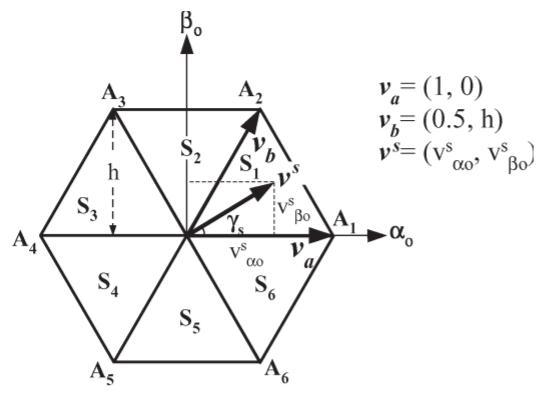
Abstract - Themajorgoalofthisresearchistodevelopa bidirectional T-type multilevel inverter based on space vectorpulsewidthmodulation(SVPWM)forelectricvehicle applications. A bidirectional multilayer dc-dc converter is usedinthisproject,whichisaneedinelectricvehicles.To balancethevoltageoftheT-typemultilayerinverter(MLI) capacitoracrossacompletedrivecycleorat-faultsituations, theproposed onesimply needstwo extra powerswitches and a capacitor. Space vector pulse-width modulation (SVPWM)isoneofthemostusedmodulationtechniquesfor amultilevelinverter.TheSVPWMforamultilevelinverter, on the other hand, is difficult to execute. The difficulty in findingthelocationofthereferencevector,calculatingontimes, and defining and selecting switching states contributes to the complexity. Based on typical two-level SVPWM,thisstudypresentsageneralSVPWMalgorithmfor multilayerinverters.Thelargeelectrolyticcapacitorsusedin T-typeMLIarereplacedwithmoredependable,longer-life film capacitors in this configuration due to the highfrequency cycle-by-cycle voltage balance between CN and CP.Theconverter'ssizeandweightwillbereducedby20% as a result of this. This frees up additional space in the chassis' space envelope for the EV battery, allowing it to growincapacity.THDandlinevoltagesaremorerippledin thecurrentsystem.TheSVPWMapproachisusedtoreduce thesedifficulties.
Key Words: (T-TypeMultilevelinverter,spacevectorpulse widthmodulation(SVPWM),two-levelSVPWM.
1. INTRODUCTION
Tosynthesizesitssteppedoutputvoltagelevels,multilevel inverters often use separated dc power sources or split capacitorscoupledtoasingledcpowersource.Thefirsttype ismorereliable,butitnecessitatesagreaternumberofdc powersourcesandpowerswitches,suchasacascadedHbridge multilevel inverter, as previously mentioned. Split capacitor-basedMLIs,suchastheneutralpointclampedNPC MLI[4],flyingcapacitorFCMLI[5],andT-typeMLI[6][7], on the other hand, required less power components. However,becausethevoltageacrosseachcapacitorisbased onanidealnaturalbalance,theirvoltagesarevulnerableto voltagedrifting,resultinginvoltageimbalanceoperations.
Thethree-phaseinverterinthepropulsionsystemofelectric vehicles is fed by a bi-directional DC-DC converter [8] [9] [10].Itregulatesthedcbusvoltagetothelevelrequiredto allowpowertoflowtotheelectricmachineindrivingmode overthedesignatedmodulationindexrange(mmmm).The bi-directionalconvertersteppedtheDCvoltageinbreaking mode (regenerative) to let power to flow in the opposite directionfromtheelectricmachinebacktotheutilitygridor electrical storage units, as in an electric vehicle. The bidirectional converter can be built as a boost converter in motoringmodeandabuckconverterwhilebraking,orvice versa, depending on the power source connected to the propulsionsystem.
Theon-timescanbeobtainedinoneoftwoways.Thefirst method is to find the triangle and then solve three simultaneousequationsforittogettheontimes,asshown in[4].Thesecondway,asshownin[5,istodeterminethe triangle and then use the specific on-time equations contained in the lookup for this triangle. Both of these systems, however, become computationally costly as the number of levels rises. The works [6] and [7] offered a general approach for obtaining on-times for multilayer inverter SVPWM in the linear modulation range [8]. Celanovic and Boroyevich [6] offer a Euclidean vector system-basedSVPWMtechniquethatisrathercomplicated due to the utilization of multiple matrix transformations. Furthermore,neither[6]nor[7]giveasystematicmethod for finding the switching states, nor a real-time implementation. Wei et al. [7] suggest a method that is a modifiedversionofthesystemin[6].Tocalculateon-times and determine switching states, this approach use the 60 coordinate system. The 60 transformation adds to the complexitybecausemostcontrolmethodssupplyavoltage reference in coordinates. The SVPWM for a multilevel inverterisperformedusingasimpleapproachproposedin thispaper.Thetechniqueisbasedontwo-levelSVPWMand maybebuiltforanylevelwithjustonecounter.Usingthe two-level approach, some studies [9]–[11] proposed multilevel SVPWM. However, these methods have some flawsthatareaddressedinthesuggestedstrategy.Zhanget al.[9]offeramethodforon-timecalculationbasedontwolevel simplification, in which the three-level space vector diagramisreducedintosixtwo-levelspacevectordiagrams.
Asegregationofthethree-levelspacevectordiagramyields the locations of the centers of six virtual hexagons. To employtwo-levelon-timecalculation,theoriginisvirtually relocatedtooneofthesixcenters,andtheaxesarerotated by 60 degrees. This strategy works effectively for three levels because only three levels require segregation. Is it possibletoextendthisstrategytohigherlevels?Theon-time calculationforleveln>3isnotincludedin[9].
Thisworktakesadifferentapproachthanalloftheprevious references and offers a general answer. It is based on a traditionalCartesiancoordinatesystem,thereforeitmaybe simply integrated with existing speed or torque outer control loops. The key features of the proposed plan are listedbelow.
1) Due to the usage of two-level SVPWM, the on-time computation is straightforward. Because the on-time calculationformulaedonotchangewiththepositionofthe referencevector,asintheoldapproach[5],nolookuptables arerequired.
2)Thetrianglewherethereferencevectorispositionedin thespacevectordiagramofann-levelinverterisidentified as integer j using a simple algebraic expression. The jth triangleamongthe(n1)2trianglesinasectorisreferredto as the triangle number j. With respect to triangle j, any switchingsequencecanbeimplemented,resultingin ease andflexibilityinoptimizingtheswitchingsequence.
3) Without significantly increasing computations, the proposed approach can be applied for any n-level (n 3) inverter.
4) The proposed system is simple to implement using a commercially available motion-control DSP or microcontroller, which typically only supports two-level modulation.Thetechniqueisdescribedindetailforathreelevel inverter before being generalized to any level. For three-level and five-level inverters, experimental findings arereported.
II. PROPOSED SCHEME
A. Proposed Method of On-Time Calculation for a MultilevelInverter
The core idea behind SVPWM is to use discrete switching states and their on-times to compensate for the required volt-seconds.Threesimultaneousequationsaretraditionally solvedtocalculatetheon-timesforatriangleofann-level inverter.
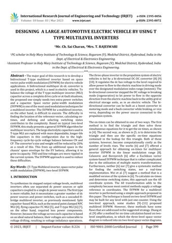
However,aclassicaltwo-levelspacevectorgeometrycanbe usedforon-timecalculationforamultilevelSVPWM.Fig.2 shows the space vector diagram of a two-level inverter. √ Everysectorisanequilateraltriangleofunitysideandh(= 3/2)istheheightofasector.
On-timecalculationforanyofthesixsectorsSi,i=1,2,...,6is same,soletusconsidertheoperationinsector1.On-time calculationisbasedonthelocationofthereferencevector within a sector. For the sector 1 in Fig. 3, the volt-second balanceisgivenby Timebalanceisgivenby
Resolving(1)alongtheαo−βoaxis,weobtain.
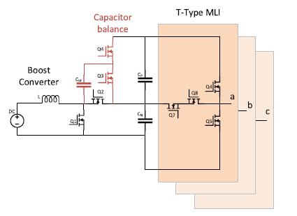
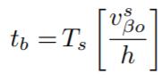
Solving (2)–(4), weobtain the following equations for the calculationoftheon-times:
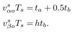
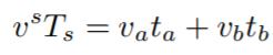
Fig. 3illustrates the proposed method of the on-time calculationforathree-levelinverter.Eachsectorofathreelevelinvertercanbesplitintofourtrianglesj,wherej=0,1, 2,3.Tosimplifytheon-timecalculation,thesetrianglescan becategorizedintotwotypes;type1andtype2.Atriangleof type1hasitsbasesideatthebottom,asshowninFig.3(b). Triangles0,1,and3areoftype1.Atriangleoftype2hasits basesideatthetop,asshowninFig.3(d).Triangle2isof type2.
triangleinwhichtherequiredreferenceislocatedandthen find (vs αo, vs βo). The on-time calculations can be performed using the geometry shown in Fig. 3(b) or (d), whichwouldresultinthesameon-timeequationsasthose foraclassicaltwo-levelSVPWM(5)–(7).Atriangleoftype1 issimilartoasector1ofavirtualtwolevelinverter.
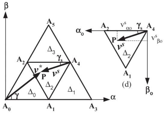
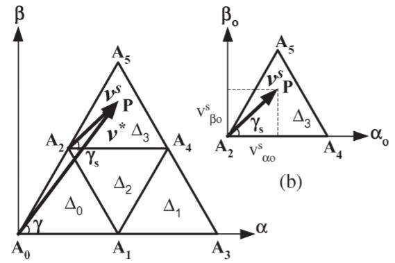
Forexample;InFig.3(a),triangle3canbeassumedsimilar to sector 1 of a two-level inverter if A2 is taken as zero vectorofthevirtualtwo-levelsectorasshowninFig.3(b). Vector A2P defines the small vector vs(vs αo, vs βo). Ontimesta(tA4),tb(tA5),andto(tA2)arecalculatedbyusing (5)–(7), where the multiplication operations are required onlyfor(5)and(6).Atriangleoftype2issimilartoasector 4 of a virtual two-level inverter. For example; In Fig. 3(c), triangle2canbeconsideredsimilartosector4ofatwo-level inverterifA4isassumedtobezerovector[seeFig.4(d)].In thisexample,A4Prepresentssmallvectorvs(vsαo,vsβo). On-timesta(tA2),tb(tA1),andto(tA4)arecalculatedby using(5)–(7).
Fig.4.BlockdiagramofSVPWMcontrol
Fig3.Spacevectordiagram virtualtwo-levelfromthreelevel.
Letusassumethatthesideofatriangleis1(unity)andh(= √3/2) is the height of the triangle. In Fig. 4(a), v∗ is the referencevectorofmagnitude|v∗|atanangleofγwiththe α-axis.Wedefineasmallvectorvs,whichdescribesthesame point in shifted system (αo, βo) [see Fig. 4(b) and (d)]. It makesγsanglewiththeαoaxis.Thevolt-secondsrequired toapproximatethesmallvectorvsintheshiftedsystem(αo, βo)shouldbeequaltothoserequiredfortheactualvectorv∗ intheoriginalsystem(α,β).Hence,wecanobtaintheontimesforanyreferencevectorbyfindingtheon-timesofthe respectivesmallvectorvs.
To achieve the volt-seconds for any reference vector in a sector of a three-level inverter, we have to identify the
Sincethetriangleswithinanysectorofann-levelinverter areanalogoustoasectoroftwo-levelinverter,theideacan beextendedtoanylevel.Thus,multilevelon-timecalculation problem is converted to a two-level on-time calculation problem.Theon-timesta,tb,andtoareafunctionof(vsαo, vsβo)foranytriangle,using(5)–(7).Therefore,theon-time calculationfor onetriangle canalsobeused foranyother triangle.
Block-DiagramExplanationoftheSchemeBlockdiagramin Fig.5givesanoverviewoftheproposedmethod.Itconsists oftwobasicunits,namelyprimaryunit(PU)andsecondary unit(SU),respectively.ThePUconsistsofapreprocessing unitandtwo-levelSVPWMunit.ThePUisbasicallyaDSPor microcontroller. The preprocessing unit does two main tasks:1)determinationofsmallvectorvscoordinates(vsαo, vsβo)and2)determinationofthesectorSiandthetrianglej ofthesmallvectorvs.Two-levelSVPWMunitobtainstheontimes to, ta, and tb by using (5)–(7). The SU is basically a mapping unit and uses memory. It fires the three-phase inverter'spre-storedswitchingsequencebasedonsectorSi, trianglejfortheon-timesobtainedfromthePU.Avertexof anytrianglecanhavemany redundanciesfora multilayer inverter(twoormorepossibleswitchingstates).Aswitching
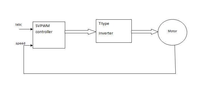
sequence for a triangle is created by combining the most appropriate switching states from all potential switching statesatthevertices.Withrespecttothetriangleandsector number, the resulting switching sequence is mapped. The on-times collected from the PU are then used to fire the switching sequence. Because the suggested technique considers the triangle to be the fundamental unit and the mappingeliminatesredundancies,anysuitablevertexcanbe chosenasthezerovector.Redundanciesatotherverticesare alsousedinthisprocess.Theorderinwhichtheon-timesta, tb,andtomustbeemployedisdeterminedbytheorderin which the switching states are selected. As a result, any redundancyforanyvertexofthetrianglecanbeusedbythe suggested technique. In contrast, when the two-level hexagonisemployedtosimulatetwo-levelmodulation,just twozerovectorredundanciesareconsidered.Asaresult,at ahigherlevel,wheremiddlevectorshavemoreredundancy, suchanapproachwillbeineffective.
III. Results
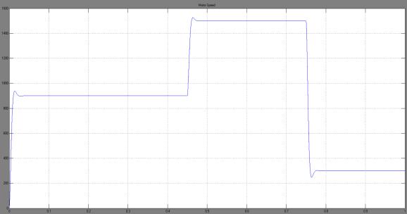
Fig8.MotorSpeedvariesfrom900rpmto1500rpmat t=0.45secandagaindropsto300rpmatt=0.75s.
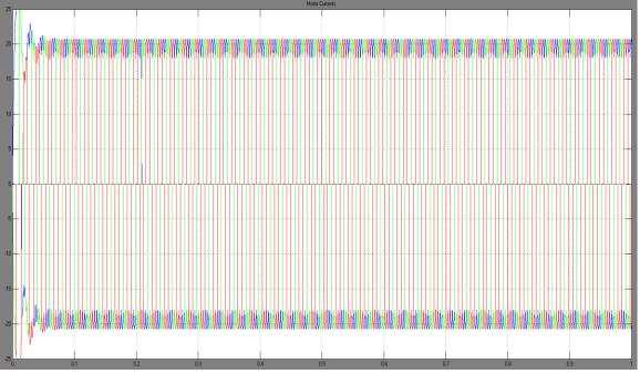
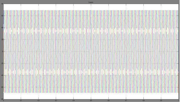
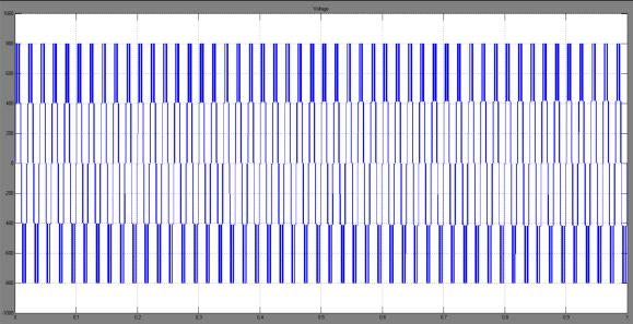
As shown in generalized multilevel inverter configuration withtheSVPWMtechniqueitcontrolsthemotorTHDsand theinverterswitchingpulse.
Conclusion
Thisresearchdescribesanewintegrationofamodifiedbidirectional dc-dc multilevel converter with a five-level Ttype multilevel inverter for electric car applications. In comparisontoatraditionalvoltagesourceinverter,theTtypeMLIusesmorepowerswitches.Itusespowerswitches with half the peak inverse voltage to provide a greater varietyofoutputvoltagelevels.AsimpleSVPWMalgorithm basedonaregulartwo-levelinverterhasbeenpresentedfor a multilevel inverter. Level has no effect on the computations.Acommerciallyavailablemotion-controlDSP ormicrocontroller,whichgenerallyonlysupportstwo-level modulation,cansimplyimplementtheproposedtechnique. The suggested technique has the benefit over previous approaches in that it can be employed with an existing torque or speed control technique based on two-level geometry.Becausesuchsystemsgiveavoltagereferencein coordinates,thesuggestedmethodmakesextensiveuseof two-level calculations and may be applied to any n-level inverter.Furthermore,thepeakinversevoltageofallpower switches and the rated voltage of all capacitors are both limitedtohalfofthepeakacoutputvoltage,reducingvoltage stress,andallowinghigherefficiencypowerswitchesinthe dc-dc side, similar to those in the T-type MLI side, to be implemented.
REFERENCES
[1] S. Kouro, M. Malinowski, K. Gopakumar, J. Pou, L. G. Franquelo,B.Wuande.al.,"RecentAdvancesandIndustrial ApplicationsofMultilevelConverters,"IEEETransactionson Industrial Electronics, vol. 57, no. 8, pp. 2553-2580, Aug. 2010.
[2]J.Rodriguez,J.-S.LaiandF.Z.Peng,"Multilevelinverters: a survey of topologies, controls, and applications," IEEE TransactionsonIndustrialElectronics,vol.49,no.4,pp.724738,Aug2002.
[3]M.Z.Youssef,K.Woronowicz,K.Aditya,N.A.AzeezandS. S. Williamson, "Design and Development of an Efficient Multilevel DC/AC Traction Inverter for Railway TransportationElectrification,"IEEETransactionsonPower Electronics,vol.31,no.4,pp.3036-3042,April2016.
[4]T.Ishida,T.Miyamoto,T.Oota,K.Matsuse,K.Sasagawa, and L. Huang, “A control strategy for a five-level double converterwithadjustabledclinkvoltage,”inProc.Ind.Appl. Conf.,Oct.2002,vol.1,pp.530
536.
[5] S. K. Mondal, J. O. P. Pinto, and B. K. Bose, “A neuralnetworkbasedspace-vectorpwmcontrollerforathree-level voltage-fed inverter induction motor drive,” IEEE Trans. PowerElectron.,vol.38,no.3,pp.660–669,May/Jun.2002.
[6] N. Celanovic and D. Boroyevich, “A fast space vector modulationalgorithmformultilevelthreephaseconverters,” IEEETrans.Ind.Appl.,vol.37,no.2,pp.637–641,Mar./Apr. 2001.
[7]S.Wei,B. Wu,F.Li,and C.Liu,“Ageneral spacevector pwm control algorithm for multilevel inverters,” in Proc. 18thAnnu.IEEEAPEC,Feb.2003,vol.1,pp.562–568.
[8] J. Holtz, W. Lotzkat, and A. M. Khambadkone, “On continuous control of pwm inverters in overmodulation rangeincludingsix-step,”IEEETrans.PowerElectron.,vol.8, no.4,pp.546–553,Oct.1993.
[9] H. Zhang, A. Von Jouanne, S. Dai, A. K. Wallace, and F. Wang,“Multilevelinvertermodulationschemestoeliminate common-modevoltages,”IEEETrans.Ind.Appl.,vol.36,no. 6,pp.1645
1653,Nov./Dec.2000.
[10]J.H.Seo,C.H.Choi,andD.S.Hyun,“Anewsimplified space-vector pwm methodforthree-level inverters,”IEEE Trans.PowerElectron.,vol.16,no.4,pp.545–550,Jul.2001.
AUTHOR DETAILS’:
Mr. Ch. Sai Charan receivedaB.Tech DegreeinElectrical and Electronics Engineering from JNTUH College of Engineering Manthani, Pannur(V), Ramgiri(M),Peddapalli(D),Telangana, India,andisStudyingM.TechinPower Electronicsat Holy MaryInstituteof Technologyand Science,Bogaram(V), Medchal(D),Hyderabad,India

Mrs. T. RAJESWARI received the B.TECH degree in EEE from Sridevi women’s engineering college, V.N.Pally, College Rd, Gandipet, Telangana, INDIA, from JNTU University and MTECH in Electrical Power Systems in Tirumala
engineeringcollege,Bogaram(v),Medchal(D),Hyderabad, Telangana,INDIA.Shehas1-yearindustrialexperienceand5 yearsofteachingexperience.CurrentlypursuingPh.DinSR University and working as an Assistant professor at Holy mary Institute of Technology and sciences, Bogaram, Medchal District, Hyderabad, Telangana, INDIA in EEE department.HerinterestareasareFACTS,Computeraided power system analysis, electrical distribution systems, Powerelectronicsetc