
Static, Thermal and CFD Analysis of Bleeder in Steam Turbine Casing Using Ansys
SHIVU G M1, CHANDAN R2 , YASHAS S 31,3M. Tech. Student, Dr. Ambedkar Institute of Technology, Bangalore, India.
2Associate Professor, Dept. of Mechanical Engineering Dr. Ambedkar Institute of Technology, Bangalore, India.

***
Abstract - The goal of this project is to provide a tool for steam-powered store transportation as well as a technique to completely eject the store from the bleed pocket. It is now more necessary than ever to have a casing and unharness mechanism that can completely expel a storage. The static and thermal loads on this shop may drive it to violently contact the bleed pocket structure once the steam from a contemporary high-performance rotary engine is discharged before falling far from the pocket. Bleed is the volume of steam produced by a rotary engine that leaves the engine's end through a pipe. This leak increases the effectiveness of the device by feeding both the deaerator and the heater (low and high). The steam that has previously operated on a rotary engine's blades is known as bleed steam. Today, we have the choice of either heating feed water with the steam or condensing it in a condenser. Most crucially, a tool for moving a store like a steam train and giving means to totally expel the store from the bleed pocket. It is getting more crucial to have a casing and unlock device that can entirely eject a store. Steam from a contemporary, improved rotary engine may be forced by the static and thermal hundreds on this shop to aggressively contact the bleed pocket structure before dissipating far from the pocket.
Key Words: Bleeder, Turbine casing, Deaerator, Steam turbinecasing.
1.INTRODUCTION
Asteamturbineisamachinethatusespressurizedsteamto generateheatthatdrivesarotatingoutputshafttocarryout mechanicalwork.In1884,SirCharlesParsonsdevelopedits modernmanifestation.
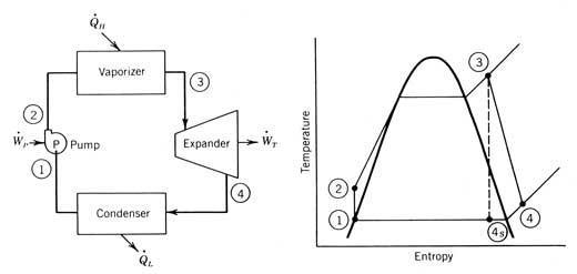
Asof1996,steamturbinesaccountedforaround90%ofall energy produced in the United States. Since they create rotationalmotion,steamturbinesareparticularlywellsuited tobeusedtodriveanelectricalgenerator.Usingavarietyof stagestoexpandthesteambringsaboutaclosermatchwith theoptimalreversibleexpansionprocedure.Itisakeyfactor in the increase in thermodynamic efficiency of the steam turbine.TheRankinecycledrivesthesteamturbine.
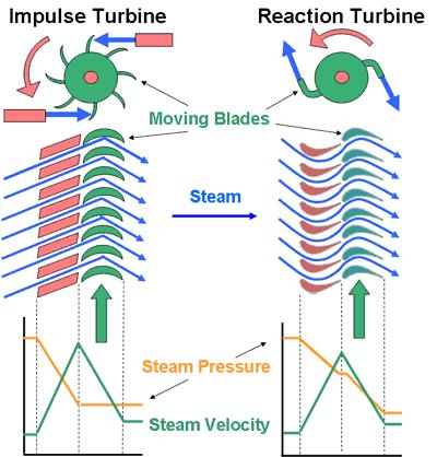
1.1 Types of Turbines Impulse Turbine
Fixednozzlesonimpulseturbinedirectthesteamflow intohigh-velocityjets.Thesejetshavehighkineticenergy, whichistransformedasthesteamjetchangesdirectioninto shaftrotationbythebucket-shapedrotorblades.Onlythe stationarybladesexperienceapressuredrop,resultingina net increase in steam velocity throughout the stage. The steam's pressure decreases from the inlet pressure to the exitpressureasitpassesthroughthenozzle(atmospheric pressure, or more usually, the condenser vacuum). Steam expandsatsuchahighratiothatitleavesthenozzleatavery rapidrate.Asignificantamountofthesteam'smaximumexit velocityiscarriedawaybythemovingblades.Thecarryover velocityor departingloss isthetermused todescribethe energylosscausedbythishigherexitvelocity.
Reaction Turbine
The rotor blades in the reaction turbine are placed in convergentnozzleconfigurations.Thistypeofturbinemakes useofthereactionforceproducedasthesteamaccelerates throughthenozzlesformedbytherotor.Steamisdirected ontotherotorbythefixedvanesofthestator.Itleavesthe statorasajetthatfillstheentirecircumferenceoftherotor. Whencomparedtotheblades'speed,thesteamthenreverses the course and picks up speed. With steam accelerating throughthestatoranddeceleratingthroughtherotor,there isapressuredropacrossboththestatorandtherotor.There isnonetchangeinsteamvelocityacrossthestage,butthere isareductioninpressureandtemperature,representingthe effortdoneinmovingtherotor.
TypesofTurbines
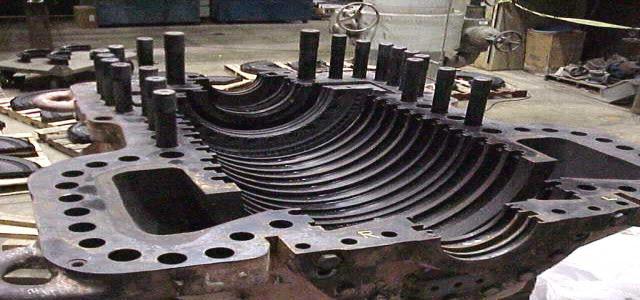
1.2 Steam turbine casing
These configurations include cross compound, tandem compound,andsinglecasingturbines.Thesimplestdesign, singlecasingunitsattachageneratortoasinglecasingand shaft. When two or more casings are directly coupled together to power a single generator, A cross compound turbinearrangementfeaturestwoormoreshaftsnotinline drivingtwoormoregeneratorsthatoftenoperateatdifferent speeds. Many large applications often employ a cross compoundturbine.
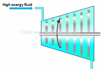
1.3 Working of Steam Turbine
When a high energy fluid (one with high pressure and temperature)travelsoveraseriesofrotorblades,theblades absorbthe fluidsenergyand begin to rotate, ittransforms thermalenergyinthefluidtomechanicalenergy.
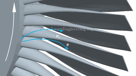
Movementofsteam
So,seriesofsuchbladewhicheventuallytransformthermal energy are the most vital part of a steam turbine. Among theserotorsetsitwouldbeobviousifyoulookedcloselyat oneofthebladesthatabladeisacollectionofairfoilcross sections from bottom to top. Such airfoils produce low pressureatthebottomandhighpressureatthetopasflow passesthroughthem.
1.2 Flange
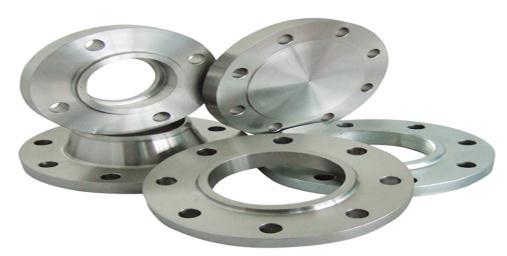
Aflangeisanexternalorinternalridge,orrim(lip),for strength,astheflangeofanironbeamsuchasanI-beamora T-beam;orforattachmenttoanotherobject,astheflangeon theendofapipe,steamcylinder,etc.,oronthelensmountof acamera;orforaflangeofarailcarortramwheel.
PressureObservedbyblades
The blade will rotate because of the resultant force in an upwarddirectioncausedbypressuredifferential.Therefore, a portion of the fluid energy will be converted into the mechanical energy of the blade. We shall closely examine energy linked with a fluid before examining energy transmissionfromfluidtoblade.
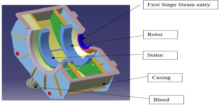
1.4 Bleed
Bleedisthequantityofsteamthatleavestheturbine's final stage through a pipe. This bleed enters to feed the deaerator and water heater (low and high), increasing the efficiencyoftheunit.
Thesteamthathasalreadyworkedonturbinebladesiswhat is known as "bleed steam”. Now the only choice left is whether to use the steam to heat the feed water or to condense it in the condenser. The first approach won't provideuswithanyusefulenergybecausetheheatwillbe transferredtocoolingwaterbeforebeingreleasedintothe atmosphereviacoolingtowers.
The secondapproach is most suitable since itallowsus to heatfeed water usingthelatent heat ofsteam.As a result, efficiency is not being lost much. Please be aware that a greater portion of efficiency would have been lost if the extractions had been made from the Main Steam line. However,thisneveroccursanyplace.
3. Analysis and Results of Casing and Bleed
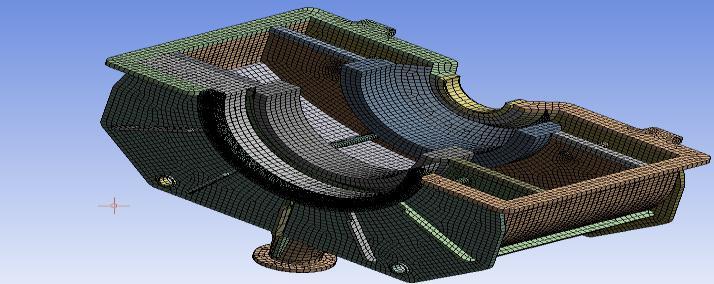
3.1 Structural Analysis Mesh Generation
The purpose of structural analysis is to ascertain howloadsaffectactual structuresandthepartsthatmake them up. This kind of research is applicable to all loadbearingstructures,includingbuildings,bridges,automobiles, equipment, furniture, clothes, soil layers, prostheses, and biologicaltissue.
1.5 Application of Steam Bleed
Scalesinthesteelindustrycanberemovedusingit. About 12bars of pressure is needed to remove scales.
It can be utilized in the sugar industry for drying purposes.About5barsofpressureisneeded.
Itcanbeutilizedfordryingpurposesin thepaper industry. About 8 bars are needed for this application.
In the pulp industry, it is employed. For this application,4barsofpressureareneeded.
Itisusedinthecementindustrytodrycement.The neededpressureisroughly14bar.
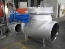
2. Design of Model Designed Model in Catia V5r17
Generating meshesfor structural analysis. Quadra meshis thechosenmeshtype.Noclarificationisoffered.Themesh qualityimproveswithhigherconvergencerates.Itindicates thattherightanswerwasfoundmorequickly.Apoormesh may miss several significant events, such as the boundary layerthatoccursduringfluidflow.Theconvergenceofthe solutionortherateofconvergencemaynottakeplaceinthis circumstance.
Steady State
According to systems theory, a system in steady state has several properties that remain constant across time. This indicatesthatthepartial derivativewithrespecttotimeis zeroforthosesystemattributesp:
Different views of bleed in casing of a turbine with meshing
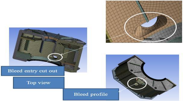
These of different views of bleed cut out
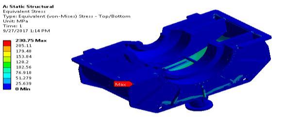
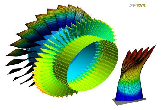
Results of the structural analysis of bleed Equivalent Stress
Equivalentstress
Numerical Approach
Calculation for diameter of Steam turbine bleeder
Data:
Casingoftheturbineextractionattheexhauststagefora30 MWturbine.
Flow-10TPH–2.78kg/s
SpecificVolume–0.26570m3/kg
Velocity–40m/s
Area=(flow ⅹspecificvolume)/velocity
Area=(2.87 ⅹ0.26570)/40=18451.4mm2
d2=(4 ⅹ18451.4)/π
d=153.3mm=6.04inch
NOTE:Flangedfittingsand7-inchpipeflangesmustbeused inaccordancewithASMEStandard16.5Class300.
Boundary Constraints for Steam Turbine Bleed Application
Thecasinginthisfigure'scorrespondingstress.Redindicates themaximumstressdistribution,whichis230.75MPa.
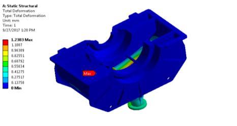
Total Deformation
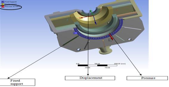
Fig-3.3 ApplyingBoundaryConditions
Thefigureillustratestheuseofboundaryconditionsinthe analysis of bleed's static structural design. Assuming that steam is moving in the Y direction, the displacement is providedatpointB.Thepressureforthebi-phasicanalysisis showninPointCoftheabovefigure.AtpointA,fixedsupport isprovided.
Thecasinginthisfigure'scorrespondingstress.Redindicates themaximumstressdistribution,whichis230.75MPa.
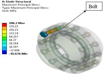
Maximum principal stress and Minimum principal stress
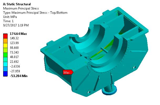
MaximumPrincipalstress
The max principal stress in the casing as determined by steadystateanalysisabout174.64MPaisrepresentedinred area.
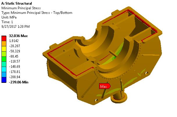
Fig-3.7 MinimumPrincipalstress
In steady state analysis, this figure shows the minimum principal stressinthecasing.Isabout32.036MPaanditis indicatedinred.
3.2 Structural Analysis of casing
Determine how loads affect actual structures and their constituentcomponentsusingstructuralanalysis
Application of Boundary conditions
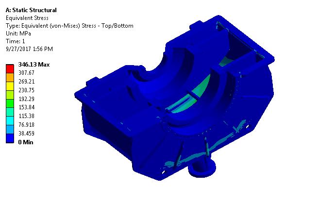
Static Structural Analysis's Results Equivalent Stress
Fig-3.9 Equivalentstress
Insteadystateanalysisandtheequivalentstress,thisfigure illustrates the stress distribution in the casing. About 346.13MPaofequivalentstressexists
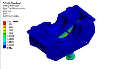
Total deformation
Fig-3.10 Deformation
Intheabovefigureredcolorindicatesoveralldeformationin thecasing.Obtainedmaximumdeformationis1.8574mm.
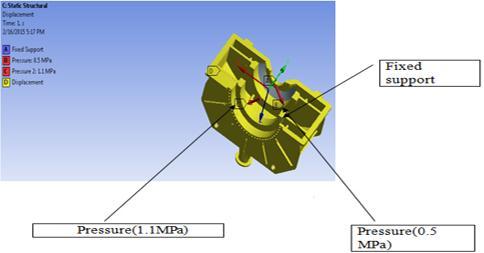
Fig-3.8 ApplyingBoundaryConditions.
Thefigureillustratestheuseofboundaryconditionsforthe staticstructuralanalysisofcasing.AtpointA,fixedsupportis provided. For phasic analysis, the pressure of 0.5 MPa is indicated at point B in the above diagram. At point C, a pressureof1.1MPaisstated.Thedisplacementisrecorded asapointintheYdirectionsincesteamisbelievedtotravel inthisdirection
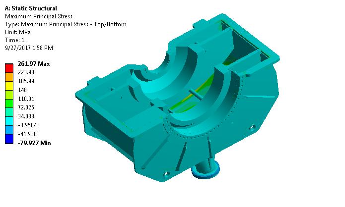
Fig.-3.11 MaximumPrincipalstress
Thisfiguredisplaysthecasing'smaximumprincipalstress. The261.97Mpamaximumprincipalstressisdepictedinred.
3.3 Thermal Analysis
A subfield of materials science called thermal analysis examines how a material's properties vary with temperature.
Thermal Analysis for Casing
Thermal Analysis at Steady State
Boundary Conditions Applications:
1. A-225°C–Temperature1
2. B-235°C–Temperature2
3. C–1.9 ⅹe-004W/mm2°C,Convectionwhichis22°C.
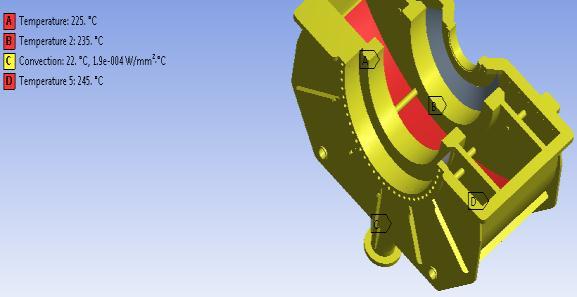
4. D-245°C–Temperature3
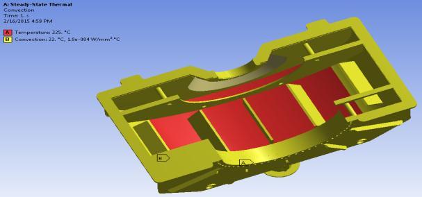
3.4 Thermal Analysis of Bleed Boundary Conditions Application
1. A-225°C
2. B-1.9 ⅹe-004 W/mm2 °C,Convectionis22°C.
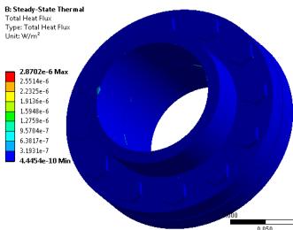
Conditions Results of Thermal Analysis of Bleed
Fig-3.12 ApplyBoundaryConditions
Thefiguredemonstrateshowboundaryconditionsareused for the casing's steady state thermal analysis. For phasic analysis, point A in the preceding diagram indicates a temperatureof225°c.PointBindicatesatemperatureof235 °C. Due to the assumption that steam will proceed in the directionofY,thedisplacementisgivenatpoint
Total deformation
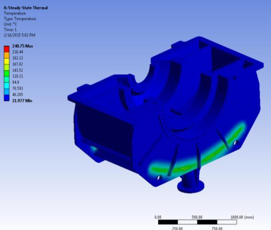
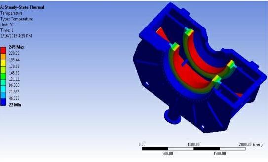
Fig-3.13 Temperaturevariation
Thetemperaturechangeinthecasingfromthebeginningof thesteamentrytotheendisrepresentedbythisfigure.The redcolorrepresentsthemaximumtemperatureof245°C.
ofsteamflow
Thetemperatureofthesteamflowinthebleedisshownin thisfigurefromthestartofthesteamentrancetothefinish. The maximum temperature is shown by red, which is 240.75°C.Thesteamtemperaturethatisescapingfromthe bleedpocketisaround100°Cintemperature.
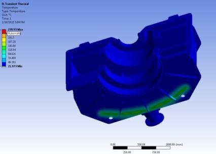
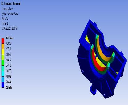
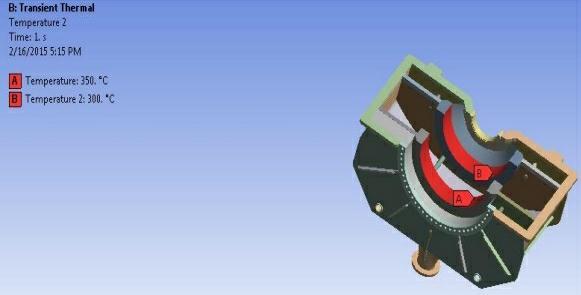
3.5 Transient Thermal Analysis
Inthefieldofmaterialsscienceknownas"transient thermal analysis", the characteristics of materials are examinedastheychangeovertime.
Boundary Conditions
1. A-350°C-Temperature1
2. B-300°C–Temperature2
Thisanalysisexaminedbytimevariation
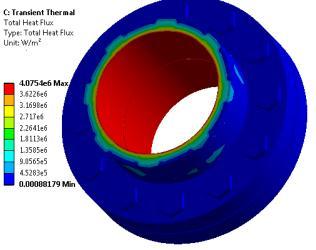
Result of Transient Thermal Analysis
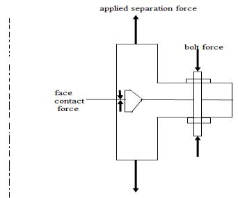
Stressonflangecausesthejointtosplit=Pressure
Properties
Thetemperaturewillbeatitspeakinthebeginning,initially assumed to be 350°c, according to the findings of the transientthermalstudyofthecasing,figure3.17Figure3.18 shows a bleed pocket's transient thermal analysis. Approximately100°Cofsteamisenteringthebleedpocket.
3.6 Flange Analysis
Design of Flange
Contact type: Surface to surface contact pairings havefrictionlessconnections.
Finemeshisnecessary:Filletflange,Bolthole,Shank cornersandblothead.
Load consideration: Bolt pretension is 49000N, Pressureis15MPa
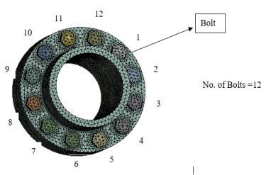
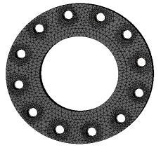
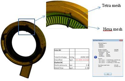
Flange Meshing
Mesh:Elementtypeused:tetrahedron
Elementsize:bodysizing:10mm(finemesh)
Forhole:refinementfactor:1(finemesh)
Forfillet:edgesizing:no.ofdivisions:100divisions (finemesh)
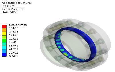
Flange Analysis Results
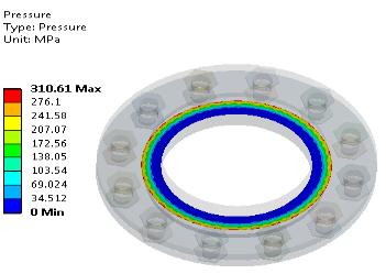
Flange Structural Analysis
Themaximumcontactpressureintheabsenceofgasketis found to be 310.61Mpa as shown in figure 3.20 and in presenceofgasketwillbe185.54Mpaasshowninfigure3.21
Thermal Analysis of Flange
D=boltnominaldiameter,inmm
P=clampload,lb
Thebolt'sthreadsbendwhenweapplytorque(maybe4-5). Wedeterminetheclamploadinthisway.Andintheindustry, torqueismeasuredbyangulardisplacement(couldbeeasily calculatedfromthepitch).Itprovidesuswithastrainvalue, which allows us to establish accurate clamp loads. One importantelementisthatboltsarenevercoated,accordingto industry.Aftersometime,thepaintwouldstarttopeeloff, andwewouldloseasignificantamountofclampload,which wouldcausethejointtoloosen.
We must also be careful not to overtighten the bolt. If we exceed the bolt's yield, itcan cause the joint to deform.Of course,undertorquingwouldcausethejointtoloosen,and along with that, wemight experience some fretting, which wouldacceleratethefailureofthecomponent.
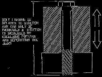
Theusedboltshaveaveryhighyield.Valuesinthe150KSI rangearenormal.Therefore,whenapplyingclampload,we do not want the bolt head to gradually deform the parent material,sincethiswouldalsoleadtoalossofclamploadand a loosejoint.Wealwaysusetoughenedwasherbecauseof this.
Thevariationoftotalheatfluxisgreaterintransientthermal statewhencomparedtosteadystate.
Insimpleterms,itistheamountofforceappliedtoa bolted joint to keep them together and prevent relative motionbetweentheparts.Therefore,theclamploadmustbe greaterthantheloadthatthejointmustsupporttoprevent the joint from coming undone. There are a few tables that wouldprovideuswithvaluesdependentondiameter(also depends on the grade). The torque is calculated using the followingformula:
T =K x D x P
Were.
T=Torque,in-lb
K=coefficientoffriction,0.20fordryand0.15forlubricated joint.(Valuesmayvaryalittlebit)
Fig-3.24 Boltloading
Applying Bolt Pretension load
Inthepast,itwaschallengingtointegratepretensionstresses from the installation torque of tightening the bolt to an analysis of a fastened flange. Analysts can more readily characterizeknownaxialloadsoradjustmentstoboltbodies orcylinderfacesbyusingtheboltpretensionloadoptionin ANSYS.
When putting a bolt body under a bolt pretension load, a coordinate system is needed. The Z-axis of the coordinate systemmustbethedirectionoftheboltaxis.
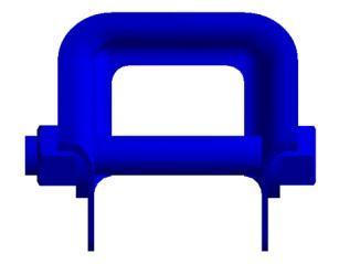
Fig-3.25 PretensionLoad
Thereare4boltpretensionloadoptions,theyare
1. Load: gives the bolt a compressive axial load (T=Dx0.2xF)
2. F=AxialLoad;D=Diameterofbolt;T=Torque.
3. Adjustment: gives the bolt a compressive axial displacement.
4. Lock: Preload displacement is fixed for upcoming loadstep
5. Open:openstheboltloadtostoptheboltfrombeing loadedatacertainpointoftheload.
6. Note:Forthepurposeofprovidingaboltpretension load,contactsettingsarecrucial.
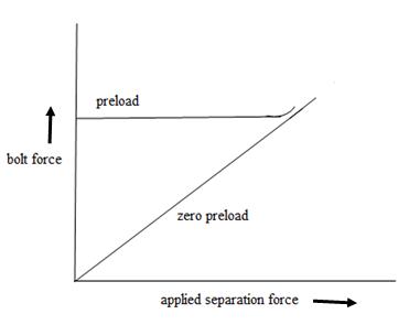
P1>P2(1-k)
Where,P1 =Pretensionofbolts
P2 =Externalload
k=0.1forgroundsurface
Checking for joint separation for with metallicgasket.
P1<Ab xYb
Where Ab =Areaofthebolt
Yb=Yieldstrengthofboltmaterial
Apply Bolt Load
Boltfacesorbodiesshouldbeloadediftheyarecylindrical.If theloadisappliedtoacylindricalface,thesoftwarewillslice thebodymeshatthecentroidoftheloadedfaceandcreate pretensionelementsinthedirectionofthecylinderaxis.The software slices the body mesh at the origin of the local coordinate system when a load is applied to a body and creates pretension elements along the local coordinate system'sZ-axis.
Contact Settings
There should be bonding between the bolt shaft and nut. Change the contact pairings along the bolt's length to No SeparationorFrictionlessifyouwantthetwocomponentsto pass one another. Bonded contact may prevent the appropriatedeformationoftheboltpretension.
Mesh Settings
To ensure that the mesh can be correctly separated in the axial direction of the bolt, it is crucial to choose a small enough mesh on the face or body that supports the bolt pretensionstresses.
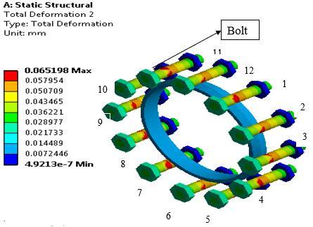
Results of Deformation in Bolts
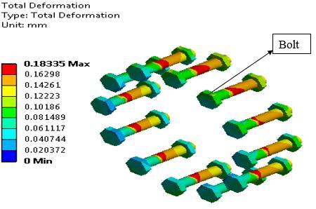
Fig-3.27
The deformation in the absence of gasket is found to be 0.18335mmandinpresenceofgasketwillbe0.065198mm asshowninfigure3.27
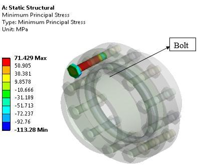
Stresses in Bolts
Themaximumandminimumprincipalstressareshownin redcolorthatis206.2Mpaand71.429Mpa.
3.8 Computational Fluid Dynamics Analysis
Computationalfluiddynamicsisabranchoffluidmechanics that use numerical methods and algorithms to solve and analyse problems involving fluid flows. The interaction of liquids and gases with surfaces governed by boundary conditions is modelled using computers. High-speed supercomputersenablethedevelopmentofbettersolutions. Softwarethatincreasestheprecisionandspeedofdifficult modellingsituations,suchastransonicorturbulentflows,is stillbeingdeveloped.Inawindtunnel,suchsoftwareisfirst experimentally validated; full-scale testing, such as flight tests,servesasthefinalstageinthevalidationprocess
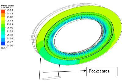
Results of Computational fluid dynamics Pressure Analysis In CFD
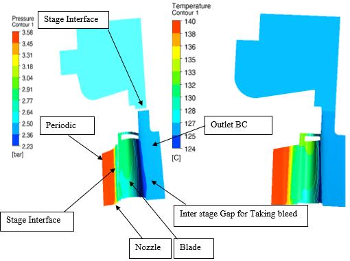
Thereare132nozzles,withaflowrateof55.3/132,andwe have applied a mass flow of 0.418kg/sec for each nozzle. Between the nozzle and blade and between the blade and cavity,wehaveusedastageinterface.
Inthefigure,steamisshownapplyingpressureasitenters thebleedpocketthroughtheshell.2.44baristhemaximum pressurethatmightpossiblyexist.2.40baristhepressureat whichsteamentersthebleedpocket.
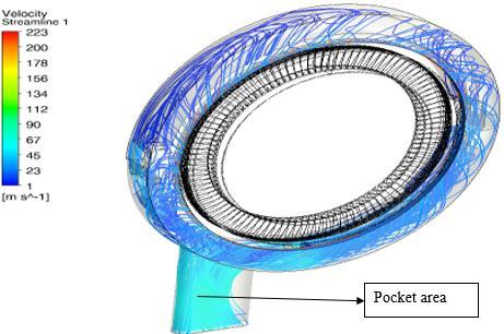
Velocity Analysis in CFD
Before emerging from the bleed pocket, the steam rotates 360 degrees. Blue color indicates the flow. Steam moves throughthebleedpocketata55m/sspeed
Results After Solving
Area=(FlowxSpecificvolume)/Velocity
Area=(2.36x0.71966)/55
Diameterofthebleed(d)=7.8inch
Numerical Approach Results
Diameterofbleed(d)=7.6inch
4. CONCLUSIONS
1. Designingableedinsteamturbinewithaspecific dimensionisthegoaloftheworkpresentedinthereport.To investigatethevariouselementsandapplicationsofsteam turbinebleed,athoroughliteraturereviewwasconducted. The various parts of the bleed were created utilising a methodthatwasdeemedsuitable.Forcreatingpartswith varioustypesofoperations,CATIAiswidelyutilised.Finally, intheCATIAAssemblypart,eachcomponentisputtogether to form a complete turbine, after which it is all tested in AnsysV14.5.
2. Due to their numerous applications, Bleed, which arestillrelativelynewonthemarket,aregarneringalotof interest.Acomplexengineeringproductlikebleedisalways being developed. Before the bleed is ready for market consumption,thereisstillmuchdesignworktobedone.The design process must take into consideration a variety of additional aspects in order to be suitable for actual applications. The production of such complex forms at microscopicsizesisanothertopicofongoingresearch.Even greater bleed could be produced with more investigation intothedesignandmanufacturingprocess.
Casingandbleedpocketstructuralanalysisis investigated. to evaluate how loads affect the casing.
Wehaveexaminedhowthethermalanalysisof thecasingandbleedpocketvariesovertime andthenwhentimeisabsent.
Computational fluid dynamics is used to measureflow.
REFERENCES
[1] Ivan Sunit Rout, Abhishek Gaikwad, Vinod Kumar Verma, Mohammad TariqThermal “Analysis of Steam Turbine Power Plants” Volume 7, Issue 2 (May. - Jun. 2013),PP28-36.
[2] Katarzyna St, Lukasz Kowalczykb, Sławomir Dykasa, Witold Elsnerb “Calculation of a 900 MW conceptual
700/720C coal-fired power unit with an auxiliary extraction-backpressure”, Journal of Power Technologies 92 (4) (2012) 266–273 Gliwice 44-100, Poland.
[3] Thamir K. Ibrahim1, M. M. Rahman,“Effect of CompressionRatioonPerformanceofCombinedCycle Gas Turbine”, International Journal of Energy Engineering 2012, 2(1): 9-14 DOI: 10.5923/ j.ijee.20120201.0226600,Malaysia.
[4] Ramesh, C.Vijaya Bhaskar Reddy, Dr. B. Jayachandr , Design and Analysis of HP steam turbine casing for Transient state condition ,International Journal Of ComputationalEngineeringResearch(ijceronline.com) Vol.2Issue.5
[5] Dr.SabaYassoubAhmed,“StudythePerformanceofthe Combined Gas Turbine-Steam Cycle for Power Generation”MathematicalTheoryandModellingISSN 2224-5804(Paper)Vol.3,No.12,2013.
[6] Malagouda Patil, Aravind Muddebihal, “To Study the SteadyStateThermalAnalysisofSteamTurbineCasing” InternationalJournalofInnovativeResearchinScience, Engineering and Technology Vol. 5, Issue 1, January 2016
[7] NaradasuRAVIKUMAR,KonijetiRAMAKRISHNA,and Alluru Venkata SITA RAMA RAJU, “Thermodynamic AnalysisofHeatRecoverySteamGeneratorinCombined CyclePowerPlant” Thermal Science2007 Volume 11, Issue4,Pages:143-156
[8] WeiliangWang,HaiZhang,PeiLiu,ZhengLi,WeidouNi, HideyukiUechi,TakumiMatsumura,“Afinite element methodapproachtothetemperaturedistributioninthe inner casing of a steam turbine in a combined cycle power plant” Applied Thermal Engineering Volume 105,25July2016,Pages18-27
[9] R.K.Kapooria, S.Kumar, K.S.Kasana “An analysis of a thermal power plant working on a Rankine cycle: A theoreticalinvestigation”JournalofEnergyinSouthern Africa,Vol19No1,February2008
[10] Abdalla,MominElhadi,Pannir,Siddharth,Mahjob,Aya Mohammed Hassan “Performance and Efficiency of Combined Cycle Power Plants” International Refrigeration and Air Conditioning Conference Paper 2273.
[11] R. Rajesh and Dr. P.S. Kishore “Thermal Efficiency of CombinedCyclePowerPlant”International Journal of Engineering and Management Research Volume-8, Issue-3,June2018