Analysis And Design of Pre-Engineered Building Using Indian And Equivalent American Code
Abhijeet Shinde1 , Dr. Nitin S. Naik 2 , Lalit N. Chaudhari 31PG Student, Department of Structural Engineering, SRES College Of Engineering Kopargaon-423603, India
2Associate Professor, Department of Structural Engineering, SRES College Of Engineering Kopargaon-423603, India

3Structural Engineer,Livio Building SystemPvt.Ltd, Pune-411028 ,India ***
Abstract - Pre-engineered buildings (PEBs) are structures that have been pre-engineered by a manufacturer to be constructed using a predetermined inventory of raw materials and manufacturing techniques that may effectively fulfil a variety of structural and aesthetically pleasingdesigncriteria. Mezzanine floors, canopies, fascias, internal partitions, and other structural accessories can be added to pre-engineered steel buildings. The buildings can also be waterproofed using specific mastic beads, filler strips, and mouldings. Preengineered structures with efficient designs can be up to 30% lighter than traditional steel structures. Less steel is required when something is lighter, which might reduce the cost of the structural structure.
Key Words: pre-engineered building (PEB), conventional steel buildings, mezzanine floors, canopies, fascia;
1.INTRODUCTION
India is a developed country. Large-scale housing constructionistakingplacealloverthecountry.Becauseher 30%ofIndia'spopulationlivesincities.Therefore,morewill bebuiltinurbanareas.Pre-engineeredsteelstructuresare manufacturedormanufacturedin-house.Componentsare manufacturedaccordingtocustomerrequirements.Detailed componentsarelaidoutandnumberedinspecificlocations, but cannot be changed. Because the rod is made from the point of view of design function. These components are manufactured modular or completely disassembled for transportation.Thesematerialsareshippedtothecustomer siteandsetup.Wedonotperformweldingorcuttingatthe customer's site. There is no manufacturing process at the customer's site. Pre-engineered Buildings (PEBs) are designed by manufacturers to be manufactured using predetermined inventories of raw materials and manufacturing methods that can efficiently meet a wide range of structural and aesthetic design needs. In some geographic industries, these buildings are also called preengineeredmetalbuildings.Historically,theprimaryframe structure of pre-engineered buildings is an assembly of Ishaped members, often called I-beams. I-beams are commonlyusedinPEBbyweldingsteelplatestogetherto
form an I-beam. The I-beams are then assembled on site (suchasboltedjoints)toformtheoverallframeofthepreengineered building. Cold-formed Z-shaped and C-shaped memberscanbeusedassecondarystructuralmembersto attach and support siding. Building exteriors can be rollformed profiled sheet steel, wood, upholstery, precast concrete, masonry blocks, glass curtain walls, or other materials.
1.1 Objectives of study
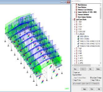
Thepurposeofthisworkistofocusontheanalysisand design of PEB Shed using STAAD-PRO Connect Addition software.
Bulletedlistsmaybeincludedandshouldlooklikethis:
Themainobjectiveofthethisstudyistoprepareareport ofPre-EngineeredsteelbuildingforIndustrialshedusing StaadProConnectEditionSoftware
TodesignPEBBuildingwithIndiancodeandequivalent American codes with use of Staad Pro Connect Edition Software, By considering uniform flange profile and compareitsresultrelatedtoweightratioinpercentage.
TodesignPEBBuildingwithequivalentAmericancodes with use of Staad Pro Connect Edition Software, By consideringdifferentflangeprofileandcompareitsresult relatedtoweightratioinpercentage.
2. LITERATURE REVIEW
An extensive study of literatures is carried out to understandtheconceptofsequentialanalysisandtheeffects ofitonstructure.Inadditiontothis,literaturesrelated to structuralloadpathirregularitiesarereviewedandbehavior ofstructureisunderstood.
2.1 Review of Literatures
1. Zende, et. al. [1] dealtwithcomparativestudyofanalysis and design of Pre-Engineered-Buildings and conventional frames.StaadProsoftwarehasbeenusedinordertoanalyze and design Pre-engineered building structures and conventionalstructures,authorsconsidered3examples.In
thefirstexample,a3DmodelofaHostelbuildinghasbeen designedandcomparedwithconventionalstructureusing conventionalsteel.ItisseenthattheweightoftaperedPEB sectionsare369.24kNwhereasforconventionalbuilding,it is found to be 491.64 kn. Pre-Engineered Building weighs 25%lessthanthatofconventionalbuilding.Inthesecond example,a2Dplaneframeofwidth44mforbothPEBand conventionalhasbeendesignedandcomparisonhasbeen madeintermsofweightofsteel.PEBstructureisdesigned foraclearspanof44mwithoutanycolumninbetween,as notincaseofconventionalframe,whereitisnotpossibleto provideaclearspantrussandhenceaninteriorcolumnis provided. It is noticed that, even though PEB structures provides clear span, it weighs 10% lesser than that of conventional buildings. Some examples of how your references should be listed are given at the end of this templateinthe‘References’section,whichwillallowyouto assembleyourreferencelistaccordingtothecorrectformat andfontsize.
2. Pérez [2] dealtwithdesignandanalysisofanindustrial steel building. Limit states, stability check. Work done by authorsfocusedonthedesignofastructuralsteelindustrial building of double-T type section located in an industrial area of Valladolid (Spain). Firstly, a linear analysis was carriedoutinpasttodimensionthestructureandcheckthat it resists according to the established regulations, the TechnicalBuildingCode,thenationaladaptationoftheEuro codes.Inthesecondplace,anonlinearanalysisisperformed with the objective of verifying the Ultimate Limit State of stability of the structural elements and of the industrial buildingasawhole.Authorssummarizesthemethodologyof the nonlinear analysis of the spatial structures of beams, whichallowsproblems of instabilitywith bending and/or torsion deformations to be solved, calculating the critical moment of lateral buckling for any load case and support conditions.
3. Sai Kiran et al. [3] studied the Comparison of Design
ProceduresforPre-EngineeringBuildings.Theeconomyof thestructureisdiscussedintermsofitsweightcomparison, between Indian codes (IS800- 1984, IS800-2007) and American code (MBMA-96), and between Indian codes (IS800-1984,IS800-2007).Themaindifferencebetweenthe IndianCode(IS800-2007)totheotherequivalentAmerican Codesareintheclassificationofthecross-sectionofthesteel member. As per Indian code, the classes of section considered for design are Plastic, Compact and Semicompact,slendercross-section.Itiswellknownthatmany PEBmanufacturersusesectionswithverythinwebsinorder to reduce the weight of the section and be economical/competitive in their commercial offers, and thesethinwebsdonotsatisfythecodalprovisionsofIS800: 2007.
2.2 Research Gap
Sufficientliteratureisavailableonanalysisanddesignof PEBstructures,butusingsamesizesofflangesofelement effectivelyItwilldefinitelyhelptoachievegreateconomyof projectwhichultimatelyaffectoverallproject.Hencemore attentionisrequiredtowardsthisissue.
╸Availableliteratureshowsthat,foranalysis,mostlyuniform flange profile is used while it is not necessary at every momenthenceitwillbemorerealistictousesectionwith fullcapacity.
3. METHODOLOGY
Metal construction of pre-engineered can be optimized to meet specific design criteria. Recent days, most Indian consultants and his PEB Vendors providers largely follow IndianandAmericandesignpractices.
Thedesigncycleconsistsofthefollowingsteps:1.Setsection sizesandbracelocationsbasedonthegeometryandloads specifiedintheframedesign.2.Calculatethemoment,shear force, and axial force at each analysis point for each load combination. 3.Compute the allowable compressive and tensile shear, axial and bending stresses at each analysis point.4.Basedontheactualandallowablestresses,calculate the corresponding shear, axial, and bending stress ratios, and calculate the bond stress ratio. 5. Design the optimal splice site and ensure that the predicted size meets manufacturingconstraints.6.Usepassoptimizationmodeto achieve optimal pass depth for next cycle and update member data file. 7. At the end of every design cycle, an analysisisperformedtoachieveoptimizationoftheflange brace.Rigidframes.
Frame Geometry: The program has the ability to handle different types of frame geometry, such as: Rigid frames, frameswithmultipleinternalcolumns,singleslantedframes, slanted frames, etc. Frames with different spans, different heights,differentslopes,etc.H.Articulatedsupports,fixed supports,subductionsupports,andsupportswithacertain degreeoffreedom.Asymmetricframes,suchasoff-center, unequal modules, or different slopes. Custom purlin and flangespacingandflangebracelocations.
Design Codes: Contains the service requirements that the design must meet. Implementation standards for design loads(otherthanearthquakes)ofbuildingsandstructures.It helpsdeterminetheseloadsonthebuildingbeingmeasured. Thekeydesigncodescommonlyusedare:AISC:American institute of steel construction manual AISI: American iron and steel institute specifications MBMA: Metal building manufacturer’s code ANSI: American national standards institute specifications ASCE: American society of civil engineers 35 UBC: Uniform building code IS: Indian
standards (IS1893-2002 PART 1 FOR EQ) and (IS 875 PARTIIIFORWIND).
4. DESIGN PHILOSOPHY
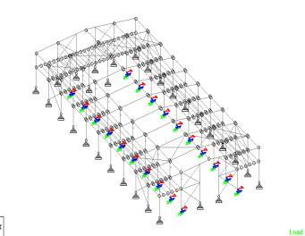
Thedesignunderconsiderationisanindustrialshedwitha freespanof35meters.Theshedwasdesignedin3Dusing STAADsoftware,withtheloadhedistributedevenlyacross thethreecoordinatesystems.H.SimulateX,Y,Zcorrectly. Dead, live, wind, temperature, earthquakes, etc. were consideredwhendesigningtheframe.Ithasastructurethat canreceivethewindloadcausedbytheopeningandclosing ofthelargesheddoorbothintheclosedstateandtheopen state.Loadcalculationsareperformedinthesamewayasfor normalframes.The(DL+WL)or(DL+LL)conditionisusually the key case driving the design because the PEB slope is small(e.g.,1in10).Supportconditionsareusuallyfixed,but selective use of fixed conditions can be advantageous, resultinginacombinationofbaseplateandanchorbolts.In the pivoted base state, the section typically tapers downwardandisboltedtothebase.Allotherconnections are usually designed as rigid connections and steel connections are moment connections that transmit axial, momentandshearvaluesbetweentheconnectedsections. Wind load calculations should refer to IS-875 pt.3 latest edition to achieve design wind pressure after careful analysisandcombinationofinternalandexternalpressure or force coefficients. Appropriate load combinations with wind loads, seismic loads and crane loads should be considered.Thebasicideaofrigidframedesignistoemploy a"fixed"or"pinned"strutbasecondition.Asturdystanchion base is a stable frame at all times and helps control the allowabledeflection(lateralfluctuation)oftheframe.Steel designers always prefer fixed base frames to fixed base frames. On the contrary, foundation design becomes a nightmareforfoundationplanners,especiallyforbuildings withlargespans.Inafixedbasedesign,theframeisrigid, butheavymomentsaretransferredtothefoundation.Weak groundmakes foundation design a tedioustask.Similarly, withpinnedsupports,theframedoesnottransfermoments to the foundation, only vertical and horizontal reaction forcesaffectthedesignofthefoundation.Itlookssimple,but duetothelongspan,controllingtheframedeflectionwitha pinned base is a difficult task. Combined stresses are typicallycheckedusinginteractivesoftwarethatcalculates sectionutilizationefficiencyandcomparedtolimits(LSDor WSD). H. An actual stress/allowable stress of 0.95 means thatthesectionisusedto95%ofitsstrength.Forthis,the totalweightoftheframeiscalculated.Manysuchthatthe sections are designed with variables such as flange thickness, web thickness, flange width, web depth, etc. so thatthewholeframeistheoreticallysafeandhasaminimum weight. Trail runs. Deflection testing is the next step. The easiest way to control this deflection is to increase the
geometry/sectionsizeoftheframe,butthatwouldincrease theoverallbuildingtonnage,whichwouldincreasenotonly the seismic force but also the later cost, so it is not recommended. Not recommended. I need a solution that allowsmetocontrolframeswayanddoesnotincreasethe sectionsize.Thebestmethodwehavebeenabletofindisto "brake" the frame to control excess deflection. In this example,stiffeners(reinforcedeaves)wereinstalledatthe height of the eaves on both sides of the structure in the longitudinal direction. The span of this eaves brace is approximatelyL/10oneachside.Intheexamplebelow,you canseehoweavesbracescanbeveryhelpfulincontrolling horizontaldeflection,makingfoundationdesigneasier.Some vendorsuse90%ofthesectionsandleave10%forpossible manufacturing, transportation, assembly and assembly errors.But thiscompetition hasledpeopletobelievethat thereisnoproblemanywhere!Thenextimportantstepisto designtheweldbetweentheflangeandtheweb.Again,the efficiency of the weld seam plays an important role. Therefore,PEBmanufacturersavoidon-siteweldingbecause a 4.5mm weld in the workshop may be better than a 6 or 8mm weld in the field.The nextstepis to designthe field joints(wherethepartswillbeassembledonsite).Theforces produced at the joints are known. Bolted connection preferablyperpendiculartotheplaneoftheframetoutilize thetensilecapacityoftheBMboltinsteadofshearcapacity. Therefore,thenumberofscrewsrequiredforconnectionis reduced. Many span reduction and lateral support techniquessuchassagbars,kneebracesandpullbarscanbe usedtooptimizethesection.
4.1. Building Input Data
Width=35meters,Length=75.50Meters,EaveHeight=24 Meters, End Bay no. and Spacing = 2 no. @ 7.62 Meters, Intermediate Bay no. and Spacing = 2 no. @ 7.62 Meters, Brickwork=3.00Meters,RoofSlope=1in10,Location= Wada,MaharashtraClearheightofStructure=9.75m,Ridge heightofStructure=1.075m.
4.2. Dead Load Calculations
Sheet weight = 4.57 kg/m2, Purlins =5 kg Bracing and Sagging = 9.5 kg, The total load transferring from these componentsare1.0KN/M2,TotalDeadload=1.0*7.5(Bay Spacing)=7.5KN/M2
4.3. Live Load Calculations
LiveLoadisconsideredfromthecraneloadingandmanual loadingduringerectionandis0.57accordingtoMBMAcode ofchapter4,LiveLoad=0.57*7.5=4.275KN/M2 .
4.4. Seismic Load Parameters
Wadacomesunderzone–III,i.Z=seismiczonecoefficient= 0.16(table2ofIS1893PART1-2002),ii.I=dependupon functionaluseofthestructures=1(fromtable6ofIS1893), iii. R = response reduction factor = 5 (table 7 of IS 1893 PART1-2002).
4.5. Wind Load Calculations
WindPressureCalculations=WindSpeed,Vb=44m/sec, Riskcoefficient,k1=1.00,Terrain,Htandsizefactor,k2= 0.98(Terrain=2),TopographyFactor,k3=1.00(class=c), DesignwindSpeed,(vz)=Vb*K1*K2*K3=44.00*1.00* 0.98 * 1.00 = 40.92 m/sec, Design wind pressure, Pz = 0.6*Vz^2 =0.6*40.92^2 = 1004.67 N/m2 = 1.00KN/M2 , Element wind Load = Pz* Bay Spacing = 1.00*7.53 = 7.53 KN/M, InternalPressureCoefficient(Cpi)=+/-0.5,External PressureCoefficientfromIS875–IIItables(Cpe):
5. RESULT AND DICUSSION
5.1. Results
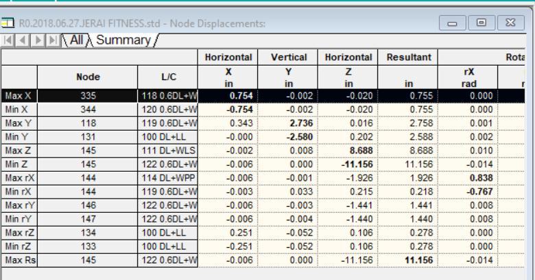
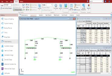
we have analyzed structures for three different codal positions as mentioned in design methodology. We have followed static non-linear analysis method for structural analysis to check results. STAAD.pro is finite element analyses software which is globally used in construction industryforstructuralanalysisanddesign.
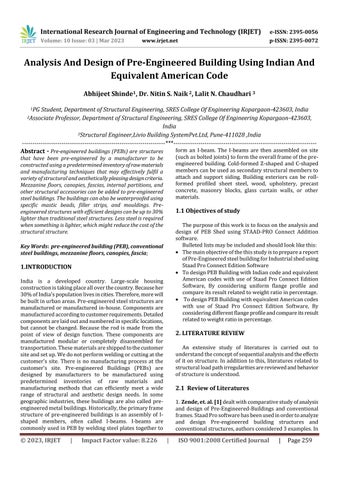
MaximumDeflectionofBuildingin Xdirection=0.754mm,Ydirection=2.736mm,Zdirection =11.156mm.
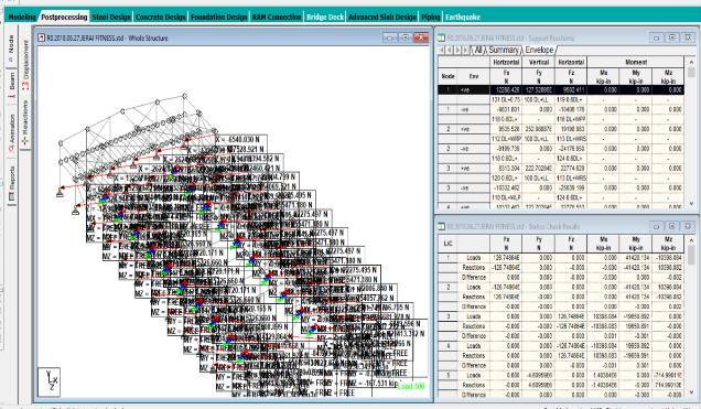
AllowableMaximumDeflectionofBuildingsaspercodeis H/400 =24000/400=60mm
Maximum Deflection of Building < Allowable Maximum Deflection.
5.2. Discussion
1.TheweightconsumptionforstructureasperIScode,by AISCwithuniformflangesandbyAISCwithdifferentflanges are1870.83KN,1070.60KNand986KNrespectively.
2.Fromthetablewestatethattheweightconsumptionratio forfirstdesigncasetosecondcasereducedby,42.77%.
3.Also,weightconsumptionratioforfirstcasetothirdcase is reduced by 47.28%. 4. Weight consumption ratio of secondcasetothirdcaseisreducedby7.87%.
4.Alsoingeneralpracticeofindustry,uniformsizeflanges areused whichare not necessarybecause if differentsize flangesareused, it will cause reduction in the weightand willbringdowncostoftheproject.
REFERENCES
1.AijazAhmadZende,Prof.A.V.KulkarniandAslamHutagi. (2013).“ComparativeStudyofAnalysisandDesignofPreEngineered- Buildings and Conventional Frames”. IOSR Journal of Mechanical and Civil Engineering (IOSR-JMCE), Volume5,Issue1,pp32-43.
2. M. Cacho-Pérez, (2017), “Design and analysis of an industrial steel building. Limit states, stability Check EngineeringStrucures”.EngineeringStructures,Volume153, Issue1,pp342-353.
3.G.SaiKiran,A.KailasaRaoandR.PradeepKumarHutagi. (2014). “Comparison of Design Procedures for PreEngineering Buildings (PEB)”, International Journal of EngineeringandTechnicalResearch(IJETR)Volume8,No:4 pp480-484.
4.C.M.Meera.(2013).“Pre-engineeredbuildingdesignofan industrialWarehouse”.InternationalJournalofEngineering SciencesandEmergingTechnologies,Volume5,Issue2,pp: 75-82.
5. A. Sravan kumar, sanjeev rao, madan mohan and dr. Sreenatha reddy. (2014). “Design and Analysis of PreEngineered Industrial Buildings (PEB)”, International JournalofAppliedSciences,EngineeringandManagement Vol.03,No.06,pp:26-29.
6.PratikR.Atwal1,VinaysinghChandrakarandPravinsingh Tomar, (2017). “Analysis and Design of Pre-Engineered Building Using IS800:2007 and International Standards”, International Advanced Research Journal in Science, EngineeringandTechnologyVol.04,No.11,pp:133-137.
6. CONCLUSION
1.Fromstudy,IthasbeenfoundthatbyIScode,weneedto provide more material weight than the American code (AISC).
2.Themajorreasonforweightreductionisduetodifferent sectionclassificationclauseincode.
3.ByusingAISCcodewecanusemore thinnersectionas comparedtoIScode,asAISCcodeallowsthinnersectionby theirsectionclassificationforprimarymembers.