FIRE FIGHTING BOGIE
1, 2,3,4,5 Students, Dept. of Electrical Engineering, Yashwantrao Bhonsale Polytechnic, Sawantwadi, India
6Lecturer, Dept. of Electrical Engineering, Yashwantrao Bhonsale Polytechnic, Sawantwadi, India

Abstract- Fire Fighting bogie is a concept which extinguishes the fire and reduce the loss of humans in hazardous conditions which is caused due to fire. In India Fire Fighting Robot and Fire Fighting Van exist in small prototype models. In abroad countries these types of robots are innovated in fire brigade vans which needs conventional supply such as water, etc. We tend to make this project in medium scale. This model is portable version of fire brigade van which use in the particular area and extinguish the fire in easy and safe way. With the help of remote control we will lead this model to the fire prone area. Then this model will extinguish this fire with the help of Nozzle located. In future also making this project in automatic level which includes electronic gears and robotics. The wheels on these bogie lift each component as they travel slowly and climb over the obstacles. When a vehicle needs to pass over an impediment, the rear wheels push the front wheels into the obstruction, which causes the front wheel to rotate and lift the front of the vehicle up and over the barrier, lifting the suspension over the obstruction one section at a time. The middle wheel is then pushed up and over the obstruction after being pressed against it by the rear tyre and pulled against it by the front wheel. The front two wheels eventually lift the rear wheel over the obstruction. The vehicle's forward motion is either slowed down or stopped entirely as each wheel crosses the impediment. As a result, this bogie can climb any obstacle with the aid of this system.
Key Words: Fire Extinguishing, Rockie Bogie Mechanism, Arduino, water tank, water pump motor.
1. INTRODUCTION
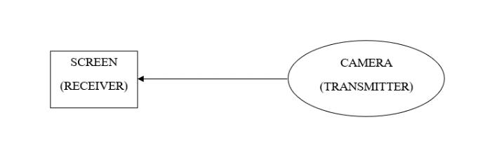
Fire safety is the set of practices intended to reduce the destruction caused by fire. Fire safety measures include those that are intended to prevent ignition of an uncontrolled fire and those that are used to limit the development and effects of a fire after it starts. The fire extinguishing vehicle can be used as a Fire Fighting Bogie which can extinguish the fire in a fire hazard zone. The advantage of using this Fire fighting Bogie is that it didn't need the direct presence of the fireman at the fire zone. Instead,thisBogiecanbecontrolledbyauserwiththehelp ofaRemotecontrol.Thebogiesuspensionweareusingisan anotherpositivefactorasthiswillhelpthevehicletomove easilyovertheobstructionsintheirpath.Special cameras
used will help them in having a view of the surroundings throughwhichtheymove.
Firefighting is the act of extinguishing fires. A firefighter suppresses and extinguishes fires to protect lives and to preventthedestructionofpropertyandoftheenvironment. In most of the cases when fire hazard occurs, the fireman willthrowhimselfintodangerforsavingthelivesofothers. Alsoinallcases,theywon'tbeabletoreachdirectwherefire occurs.Thedirectpresenceoffiremanwillmaketheirlifeis atriskinmostcases.
Anotherimportantpartweareintroducingtothefiresafety is Rocker-bogie suspension systems. This system will providethevehicletomovemoreeasilyoverthepathwhich iscoveredwithobstructions.Thewayinwhichrockerbogie isbuiltwillhelpthevehicletoclimbovertheobstructions whicharetwiceitssize.
2. METHODOLOGY
The fire fighting bogie is basically mini version of fire brigade van. The fire brigade van is consist of water tank whichhavecapacityof3000ltr-6000liter,longpipeswhich is use to carry water, nozzle which is use to throw pressurizedwaterforextinctionoffire.Mainlyourprojectis basedonthisprinciplebutinsmall insizewhichisusein anywhere.
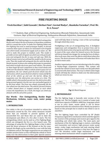
The fire fighting bogie have controlled by RF (Radio Frequency)signaldrivemechanismwhichsendthesignalto thereceiveroftheprototypeandreceivergivesignaltothe controlling unit which take action. The main parts and mechanismofthefirefightingbogieismotors,controlling unit transmitter and receiver, high pressure water pump motor, rocker bogie mechanism and tank steering wheel mechanism. Before here question is that how the bogie is run? We introduce rocker bogie mechanism and tank steeringwheelmechanismwhichisexplainbelow.
Therocker-bogiedesignconsistingofnospringsandstub axlesineachwheelwhichallowsthechasistoclimboverany obstacles, such as rocks, ditches, sand, etc. that are up to doublethewheel'sdiameterinsizewhilekeepingallwheels on the ground maximum time. The Rocker-Bogie design, whichhasstubaxlesforeachwheelandnosprings,enables therovertoclimboverobstacleslikebouldersthatareupto twice as large as the wheel's diameter while maintaining contact with the ground with all six wheels. The centre of gravity's height determines the tilt stability, as it does for anysuspensionsystem.Systemsthatusespringsaremore pronetotippingastheladensidegives.Inordertoreduce dynamicshocksandsubsequentdamagetothevehiclewhen navigating large obstacles, the system is intended to be employedatslowspeedsofabout10cm/s.Eachwheelhasa practicallyidenticalload.Ithasnojointsorsprings,which helpstokeeptheamountoftractiononeachwheelthesame. can maintain all 6 tyres on the ground while scaling over obstaclestwicethesizeofthewheel.Thebulkcanvirtually beliftedbyonewheelalone.Thecentreofgravity'sheight determines the tilt stability, as it does for any suspension system.ThesuspensionsystemutilisedbytheMarsrovers hasbeentheRocker-Bogiesystem.Nowadays,NASAfavours thisdesign.
2.Tanksteeringwheelmechanism-
Tanksturnbyvaryingthespeedofthetracksononeside, causing the tank to turn in the direction of the slower or stoppedtrackorbyturningthetracksinoppositedirections. Onetrackgoesforward,theotherinreverse.Thiscanallow thetanktoturninplace Tanksandothercontinuoustrack vehiclescanturnthankstoanksteeringsystems.Theonly waytosteeristospeeduponetrack,slowdowntheother (orreverseit),ordobothatoncebecausethetrackscannot beangledinrelationtothehull(inanyoperabledesign).By combiningsteerablewheelswithfixed-speedrails,half-track vehiclesavoidthis.Earlysteeringsystems,whichoftenused
aclutchtodecreasepowertoonetrackandslowitdown, were adapted from tracked industrial vehicles. These designs have a number of drawbacks, especially while runningfastorclimbinghills,asthetotalspeedslowsdueto the loss of power. A challenging design challenge is to provide electricity to both tracks while rotating them at variousspeeds.Regenerativesteeringisatermforanumber of more sophisticated systems that were created, particularly during World War II. Regenerative steering maintains power to both tracks while steering. In some, a feature known as neutral steering enabled one track to advancewhiletheotherreversed,allowingthetanktospin in place. The British double differential design of 1924, whichwasimitated by both theUSandGermany,wasthe firsttrulysuccessfulsystem.
We use these method by combine it because rocker bogie mechanism has suspension and tank steering wheel mechanismhasturningmechanism.Weusethisprincipleto run the bogie. To get an torque and speed we use PMDC motor which is sufficient to run the bogie with the load capacityof50kg.Itisalsoreducecostoftheproject.Ifusing BLDC motors, also give high speed and high torque; additional equipment like BLDC controller high voltage batteryconversionunitismustbeinstallwhichisincrease overall budget of the project. The brain of the bogie is transmitterandreceiverwhichusetotakeactionwhichis required for operation. To control the bogie we had two optionsi.e.Motorcontrollerordriverandrelaymodules.We take relay modules because weuse low power motor and lowvoltagebatterytooperatesystemsoitissufficient.
Arelayisanelectromechanical devicethatcanbeused to makeorbreakelectricalconnections.Itconsistsofflexible moving mechanical parts that can be electronically controlled via electromagnets. A relay is basically like a mechanicalswitch,butratherthanbeingmanuallyturnedon oroff,itcanbecontrolledbyanelectricalsignal.Also,this working principle of relays is only applicable to electromechanical relays. A core is wound with copper windings(formsacoil)onacasing.Amoveablearmatureis madeupofaspringsupportorstand-likestructurelinkedto oneendandametalcontactconnectedtotheother,bothof whicharearrangedabovethecoreinsuchawaythatwhen thecoilisactivated,itattractsthearmature.Themoveable armature is commonly seen as a common terminal to be linkedtoexternalelectronics.Therelayalsohastwopins, ordinarilyclosed and normallyopened(NCandNO), with the normally closed pin connected to the armature or the common terminal and the typically opened pin left unconnected(whenthecoilisnotenergized).
Acorewithcopperwindings(formingacoil)isplacedover thecase.Amovingarmatureconsistsofaspringsupportor
post-likestructureconnectedatoneendandametalcontact connected at the other end. All of these arrangements are arrangedonthecoreinsuchawayastoattractthearmature whenthecoilisenergized.Amovablearmatureisgenerally considered a common terminal that is connected to an externalcircuit.Therelayalsohastwopins,normallyclosed andnormallyopen(NCandNO),thenormallyclosedpinis connected to the armature or common, and the normally open pin remains free (when the coil is not energized). if not). When the coil is energized, the armature moves and connects the normally open contacts until current flows throughthecoil.Whenthepoweristurnedoff,itmovesto thehomeposition.
Relays are used to control small loads of 15A or less. Electromechanical relays are commonly used in motor circuitstocontrolthecoilsofmotorcontactorsandstarters. Other applications include switching solenoids, indicator lights,audiblealarms,andsmallmotors(1/8HPorless).The relay'scoilisenergizedbythelow-voltage(12-V)source. Closingandopeningtheswitchenergizesandde-energizes thecoil.This,inturn,closesandopensthecontactstoswitch theloadonandoff(smallmotors).Soforthatweuserelays ascontrollingunit
4.Motorcontroller-
Amotorcontrollerisadevicethatcoordinatestheoperation ofanelectricmotor.Inman-madeelevators,motorcontrol generallyreferstothedeviceusedinconjunctionwiththe control panel orVFDtocontrol theoperationofthehoist. Enginecontrolsoftenincludemanualorautomaticmeansfor starting and stopping the engine, selecting forward or reverse,acceleratingordecelerating,andcontrollingother operating parameters. In addition, motor controllers can protectartificialliftsystemsbyregulatingorlimitingtorque andprotectingagainstoverloadsandfailures.Manymotor controllers include additional functionality such as data acquisition, data logging, and application-specific control logic. Motorcontrollersacceptpowersupplyvoltagesand provide signals to motor drives, which are connected to motors.Theyareusedtoprogrammaticallystart,stop,and operatemotors.Motorcontrollerscanbeusedtogentlystart orraisethespeedofamotor,toboosttorque,ortoreverse themotor'srotationalorientation.Theycanalsobeutilised tominimisecostbyemployingthinnercableandreducedamperage devices to regulate the motor. Controllers are employed owing to operating system requirements, installationconstraints,ortoenhancemotorefficiency.
5.DCDoublePumpSprayer-
DC powered pumps transfer fluid in a number of ways by usingdirectcurrentfromamotor,battery,orsolarpower. Motorizedpumpsarecommonlypoweredby6,12,24,or32 voltsofdirectcurrent(DC).Photovoltaic(PV)panelswith
solar cells that create direct current when exposed to sunlight are used in solar-powered DC pumps. A 12 volt water pump is perfect for providing flowing water to a recreational vehicle (RV), towed camper, or powered camper. Its small size saves room in the limits of an RV's fairly limited interior. Most crucially, its capacity to be supplied by a standard 12 volt direct current (DC) automotive battery ensures flowing water regardless of where the RV is parked, whether near a municipal power supply or not. A 12 volt water pump is often positioned adjacenttothefresh-waterholdingtankinastandardRV. The pump is connected to an electrical panel, which is connectedtoaseparate12voltbatteryorbatteries.The12 voltwaterpumpisoftenequippedwithtwohoses,onefor pulling water from the holding tank to the pump and the otherforconnectingthepumptothetaporfaucet.Whenthe pumpisturnedonatthepanel,alittleimpellerinthepump suckers,orpulls,waterfromthetankandpushesittowards thetap.
Construction-
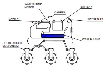
BrushedMotor
Abrushedmotorisatypeofelectricmotorthatusesbrushes and a commutator to convert electrical energy into mechanicalenergy.Itconsistsofarotor(therotatingpart) and a stator (the stationary part), which contains a set of electromagnets.
Whenanelectriccurrentisappliedtothebrushes,itflows throughthecommutatorandintothecoilsoftherotor.This createsamagneticfieldthatinteractswiththemagneticfield ofthestator,causingtherotortorotate.Astherotorrotates, the brushes make contact with different segments of the commutator,whichchangesthedirectionofthecurrentin therotorcoilsandkeepstherotorspinning.
Brushedmotorsaresimpleandinexpensive,andcanbeused inawiderangeofapplications,suchasintoys,powertools, and small appliances. However, they have some disadvantages,includinglimitedlifespanduetothewearof
thebrushesandcommutator,lowerefficiencycomparedto othertypesofmotors,andthegenerationofelectricalnoise andsparks.
3. HARDWARE IMPLEMENTATION
4. CONCLUSION
Wetrytobuildarealtimefirefightingbogiewhichmovesin aconstantspeed,identifythefireandthenextinguishitwith thehelpofpumpingmechanism.Thisprototypeiscompact insizesoitcanuseinsmallareaseasily.Mostofthetimefire fightertotakerisktogivelifetocommonmantotrapinfire .fireaccidentareasthisareasfirefightertaketimetoreach their.Somainpurposeofprojectistogiveafirefightingvan topeoplewhichtheycanaffordatreasonablepriceandfire fightervanarefastavailabletofireaccident.
5. FUTURE SCOPE
Wecanaddelectronicandprogrammingdevicesformultipurposessowecanoperatefirefightingbogieremotecontrol and automatic. Since automatic fire fighting bogie can be made completely automatic by adding some additional componentsaswellasinstallingGPSlocationtotracklive location. We can also add flame sensor then it can automatically detect the fire accident and do automatic extinctionwhichcanbealsocalledasfirfightingrobot.We canalsoaddmoreprotectiontofirefightingbogiebecause there are electronic components in it. To make it at automatic we can add AI, so that it could be smart firefightingrobot.
REFERENCES
Fig.3.1 BlockDiagram
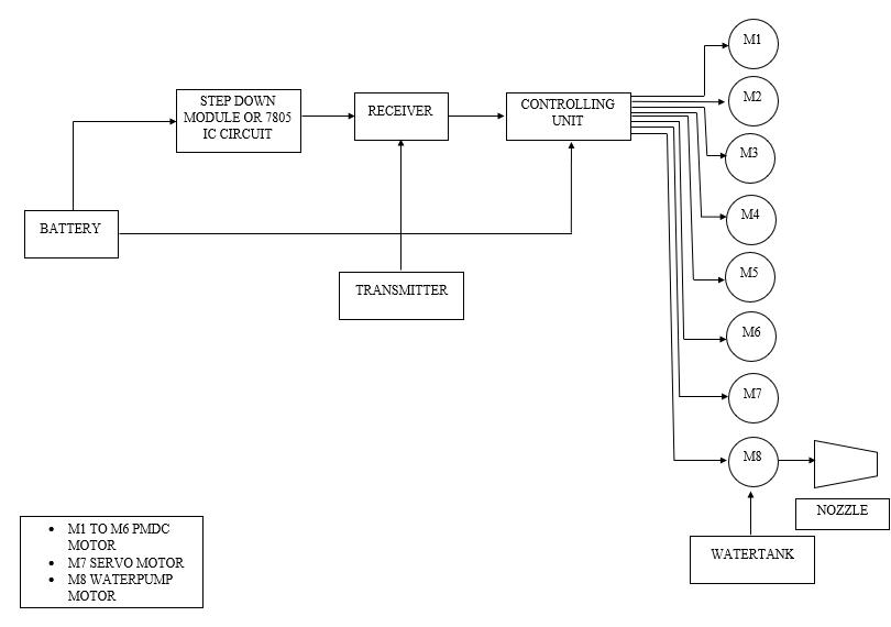
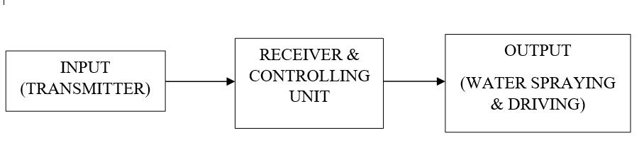
The above diagrams represent the arrangement of fire fightingbogie.Thisbogieisuseforwheretheparticulararea isfiredupandanyfirebrigadevanorfiremanisunableto reachthere.Itbasicallytheminiversionoffirebrigadevan. Itconsistofbatterywhichprovidedcpowersupplytotheall circuitry.Transmitterandreceiverisusetosendandreceive therfsignalwhichbogieisoperatedbyremotecontrolalso ititactasabrain.Theheartofthesystemiscontrollingunit whichtakingsignalbyreceiverandtakeactionthatwhichis requiredmeanswhichmotorwill berun.Todrivethethe bogiehere6motorsisavailablewhichpairly2isoperated simultaneously.Remaining2motorsisconnectedinmiddle to give torque for bogie. For visualization purpose the cameramoduleisaddedwhichtransmitthesignalwirelessly and the video is shown by the mobile screen through the app. It gives visualization for where the bogie goes to extinguish the fire. The main purpose of this project is extinguishthefireusingwatersprayerwhichispossibleby thewaterpumpmotortothrowthehighpressurizewater. Tostorethewaterthewatertankisputinthebogiewhich carrymaximum20-30literwater.
[1] Fire Fighting Robot, Author-PramodB.N.,HemalathaK. N.,PoornimaB.J.,HarshithaR.,Oct.2019
[2] Fire Fighting Robot,Author-K.ShamiliDevi,Akhileswar, Ch.Vinayaka,M.Karthik,Y.K.Viswanadham,July2020
[3] Fire Fighting Robot,Authors-NikitaKose,Chandrakala Khot,MamtaBandhekar,AnshuSahare,J.Shelke,Volume.07 Issue.2Feb2020
[4]Design & Development Of Fire Fighting Robot, AuthorsDnyaneshS.Kadu,PoojaV.Kale,JeevanD.Kadam,TejrajR. Late,Amol SuradkarAmol Suradkar,Volume.07Issue. 05 May2020
[5]Unmanned Multipurpose All Terrain Rover Using Rocker Bogie Mechanism.Authors-DeviR,B.Dharrun,P.GokulRaj, C.Gowtham,A.S.Kabilan,02August2021.
[6]Study Of Rocker-Bogie Typed Mobile Robot For Driving, Climbing And Standing Upright. Author- Eunho Seo, JooyoungChun,HunkeonKo,SanginPark,DongJinHyun,28 December2021