Review on Enhanced EV technology: Wireless charging system and performance improvement with MLI
Vishal Chaudhary1 , Mahendra Lalwani21Research Scholar (Power System), UD, Rajasthan Technical University, Kota, India

2Associate Professor (Electrical Engineering), UD, Rajasthan Technical University, Kota, India ***
Abstract - Electric vehicle research has been advanced in several nations in order to lessen reliance on oil and environmental pollution. The implementation of EVs, especially battery electric vehicles, is considered a solution to the energy crisis and environmental issues. This paper provides a comprehensive review of the technical development of EVs and emerging technologies for their future application. In addition, the energy crisis and the low energy efficiency of conventional vehicles also offer a good opportunity to develop electric vehicles. Today, many recent developments focus on improving electric vehicles and their components, particularly regarding advances in batteries, energy management systems, autonomous features, and charging infrastructure. In current times wireless charging system of electric vehicle technology is trending and in several countries, there is a lot of work done on multilevel inverters for improving the performance of electric vehicles.
Key Words: Electric Vehicles, Wireless charging system (WCS), Multilevel inverter (MLI), Total harmonic distortion (THD), Series-Series compensation
1. INTRODUCTION
Energy and environmental problems have been brought on by the growing number of internal combustion cars that use non-renewable conventional fuels [1]. Since traditional automobiles generate air pollution and oil dependence, many nationshaveadoptednewenergyvehicles(NEVs)asalternatives[2].
India produced 3202 million metric tonnes of carbon dioxide equivalent in 2014, providing for 6.55% of the world's overallemissionofgreenhousegases.Energy-relatedactivitiesaccountfor68%ofgreenhousegasemissionsinIndia,with agriculture,industry,betterlanduseandforestrypractices,andwastecontributinganadditional19.6%,6.0%,3.8%,and 1.9%[3].By2030,Indiawantstohave30%ofitsprivatecarselectricandallofitspublic transportationtobeelectric[4]. OneofthemajorchoicesmadeduringtheGlobalMobilityConferenceinNewDelhiwasthis.Morethan70%ofpollutionis produced bythetransportindustry, whichuses70%of all fossil fuels. TheGovernmentprovidesa lowerGST at12%on electricvehicleswhiletheGovernmentlevies28%GSTpluscessforpetrolanddieselcars[5].
BecauseofthelowproductionofEVs,theirentiremarketshareinIndiaisquitesmall.TheRevaElectricCar,thecountry's first electric vehicle brand, introduced its model in the early 2000s with an emphasis on producing cheap vehicles using advancedtechnology[6].
Inthisreviewpaper,wefocusedontheperformanceofEVswhichisrelatedtoinverters,andalsodiscussedthewireless charging technology for EVs. Wireless charging technology for EVs is a great idea for safety purposes. The wireless charging system has two types, static wireless charging system, and dynamic wireless charging system. There will be variousadvantagestowirelesschargingoverwiredcharging.Theoperatingcostsarereduced,buttheinitialinvestmentis highlysignificant[7].
InIndia,theMumbai-based startupPMVhasunveileditsfirst electricvehicle.The nano-sizedEV, known asthe EaS-E,is nowthemostreasonablypricedelectricvehicleinIndia[8].
Inthispaper,wereviewtheimpactofMultilevelinvertersonEVs.WediscussedwhichfactorswillvaryorimproveinEVs withthehelpofMLI.ThefactorswhichvarywithusingMLIisliketotalharmonicdistortion,efficiency,losses,etc.
2. Methodology:
In this paper, we have reviewed the electric vehicle new technology and performance which is based on the inverter`s Totalharmonicsdistortion(THD).Thenewtechnologydiscussesalongwithawirelesschargingsystem(WCS)forelectric vehicles.WCSofelectricvehiclesisaverytrendingtopicinrecenttimesforresearchers.
Thispaperisdividedintosixsections.Reviewofmultilevelinverterandwirelesschargingsysteminfirstsection.Section III consists of, Country which implemented a wireless charging system. This section also consists the classification and comparison of different WPT technology for EV charging and a summary of the wireless EV charging project. Section IV consistsof,ImpactandusesofMLIinEVsthissectioncontainstheapplicationofMLIanditsadvantagesinEVapplication. InsectionV,consistsofdifferenttypesofEVchargingstandards.InlastsectionVI,itconsistsdiscussionandconclusion of thispaper.
So,basicallyinthisreviewpaper,wediscussedadvantagesofMLI,thebenefitsofWCSforEVs,andalsodiscussedvarious technologyforchargingEVs.
3. Country which implemented wireless charging system:
In an attempt to develop a zero-emission taxi system by as early as 2023, Oslo will become the first city in the world to implementWCSforelectrictaxis[9].
Theideaistomakechargingelectrictaxisassimpleaspossiblebecauseitisnowdifficult,expensive,andtime-consuming. Thetaxiscanbechargedwhiletheywaitinwhatisknownasataxirank,oralonglineofcabswaitingforcustomers,using induction,amoreenergy-efficientchargingmethod.Thecabswillbeequippedwithchargereceivers.Thecabscanthenbe chargedforupto75kWusingchargingplatesthathavebeeninstalledintheground.TheaveragepowerofthecurrentAC chargersis22kW[10].
There are several types of wireless power transfer technology, which are mentioned in Table 1 and also discussed their power,efficiency,andrangeofWPT.
Many countries in the world are currently working on the wireless charging technology of EVs and they are working on several projects described in Table 2, which consist location of the project, power, air gap, and efficiency of wireless chargingofEVs.Table3consistsoftheEVbatteryinformationandpowertransferlevelcomparisonofchargingmethods. Table4consistofvarioustypeoffeaturewithchargingtechnology.
2:7.7kW
WPT3:11kW
Efficiency 3.3kWoutputwith10cmgap:88.8% Greaterthan90% Upto90%gridtobattery
Test GEN 1 system: Chery Volt, Nissan
2system:TeslaModelS,BMWi3
and 6.6kW:Delta E-4 7kW:RollsRoycePhantom102EX 20kW:DraysonB12/69
Others Get20-25milesofrange/hourparked Power transfer solution have been developed to suit a broad range of vehicletype
DelphiAutomotive
4. Impact and uses of MLI in EVs:
Duetotheir outstanding qualities,MLIisattracting interest inseveral medium- to high-power, high-voltage applications. MLIhasanumberofkeybenefits,includinglesselectromagneticinterference,higherpowerquality,andlessvoltagestress and loss of each individual semiconductor component [13]. MLIsolutions are preferred in these applications due to the increasedpowerandinputvoltageinelectrifiedtrains,tramways,andships.TheMLIisalsousedtoimprovetheefficiency ofEVsandincreasetheirreliabilityofEVs.TheoutputpercentageofTHDnearszeroasthenumberoflevelsincreasesto infinity,butthecostofimplementingthehigherlevelincreasessignificantly[20].ThereisonedemeritofMLIisthecost of the system increases as compared to the single-level inverter. MLI has the capability that it can operate without transformershenceitenablingtransformerlessoperation.
It is common for MLI to have a modular structure. Due to its modularity, the system offers greater voltage and current capabilities [16]. Table 5 shows the maximum DC voltage and the conventional structures in different traction applications.
5.
ManyworldwidestandardsincludeEVcharginginfrastructure.WhileIECiswidelyutilizedusedinEurope,SAEandIEEE areusedbymanufacturersbasedintheUnitedStates.JapanhasitsEVchargingstandardnamedCHAdeMO.Chinausesthe Guobiao(GB/T)standard(issuedbytheStandardizationAdministrationofChinaandtheChineseNational Committeeof ISO and IEC) for AC and DC charging, where GB/T AC charging standards are similar to IEC standards. Table 6 consist wirelesschargingstandardandpublishedyear.
6. Discussion/Conclusion:
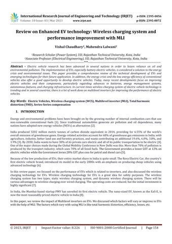
In this review paper, we have discussed emerging and enhanced EVs technology with multilevel inverters (MLI) and wirelesspowertransfersystemswithdifferenttypesoftopologiesandweusedahighlyefficienttopologysothattheEVs model has high efficiency and greater reliability. The WPT topologies are four types which are Series-Series (SS), SeriesParallel(SP),Parallel-Series(PS),andParallel-Parallel(PP).Inthesetopologies,theSStopologyhasgreaterefficiency,so in EV charging, we use the SS topology. In terms of the emerging technology of EVs, the wireless charging system is the most interesting and highly recommended topic and when we discussed the efficiency of the system we focused on the minimization of losses. By using MLI, total harmonic distortion will be less, so the efficiency and performance of the systemwillbeincreased.
References:
[1] Q. Qiao, F. Zhao, Z. Liu, X. He, and H. Hao, “Life Cycle Greenhouse Gas Emissions of Electric Vehicles in China: CombiningtheVehicleCycleandFuelCycle,”Energy,2019,doi:10.1016/j.energy.2019.04.080.
[2] A.Review,“TechnologyDevelopmentofElectricVehicles :AReview,”pp.1–29,2020.
[3] https://www.climatelinks.org/resources/greenhouse-gas-emissions-factsheet-india
[4] K. Sreeram, P. K. Preetha, and P. Poornachandran, “Electric Vehicle Scenario in India: Roadmap, Challenges, and Opportunities,” Proc. 2019 3rd IEEE Int. Conf. Electr. Comput. Commun. Technol. ICECCT 2019, pp. 1–7, 2019, doi: 10.1109/ICECCT.2019.8869479.
[5] "ElectricVehicleMarketinIndia“,enincon.com,January18,2018.
[6] S.Goel,R.Sharma,andA.K.Rathore,“AreviewonbarrierandchallengesofelectricvehicleinIndiaandvehicletogrid optimisation,”Transp.Eng.,vol.4,no.January,2021,doi10.1016/j.treng.2021.100057.
[7] V. Chaudhary and M. Lalwani, “Wireless Power Transfer with SS Compensation Topology for EVs Wireless Charging System,”vol.17,no.6,pp.598–603,2022.
[8] https://auto.hindustantimes.com/auto/electric-vehicles/pmv-electric-launches-its-first- ev- eas-e-for-rs-4-70-lakh41668582263454.html
[9]https://www.tnp.no/norway/panorama/norway-introduced-the-worlds-first-wireless-electric-car-charging-stations/
[10]
https://www.indiatimes.com/auto/current/with-world-s-first-wireless-charging-stations-for-electric-taxis-osloeyes-a-zero-emission-cab-system-by-2023_-364158.html
[11] C. Qiu, K. T. Chau, C. Liu, and C. C. Chan, “Overview of wireless power transfer for electric vehicle charging,” 2013 WorldElectr.Veh.Symp.Exhib.EVS2014,pp.1–9,2014,doi:10.1109/EVS.2013.6914731.
[12]X.Mou,D.T.Gladwin,R.Zhao,andH.Sun,“Surveyonmagneticresonantcouplingwirelesspowertransfertechnology forelectricvehiclecharging,”IETPowerElectron.,vol.12,no.12,pp.3005–3020,2019,doi:10.1049/iet-pel.2019.0529.
[13] A. Poorfakhraei, M. Narimani, and A. Emadi, “A review of multilevel inverter topologies in electric vehicles: Current status and future trends,” IEEE Open J. Power Electron., vol. 2, no. February, pp. 155–170, 2021, doi: 10.1109/OJPEL.2021.3063550.
[14]M.N.Shivanand,Y.Maruthi,P.BabuBobba,andS.Vuddanti,“AcaseStudyonwiredandWirelesschargerstandards in India for Electric Vehicle Application,” E3S Web Conf., vol. 87, no. 201 9, pp. 1–6, 2019, doi: 10.1051/e3sconf/20198701017.
[15]H.S.Das,M.M.Rahman,S.Li,andC.W.Tan,“Electricvehiclesstandards,charginginfrastructure,andimpactongrid integration: A technological review,” Renew. Sustain. Energy Rev., vol. 120, no. February, 2020, doi: 10.1016/j.rser.2019.109618.
[16]https://electricalvoice.com/advantages-and-disadvantages-of-multilevel-inverter/
[17]N.Iqteit,K.Yahya,andS.AhmadKhan,‘WirelessPowerCharginginElectricalVehicles,’Wirel.PowerTransf.–Recent Dev.Appl.NewPerspect.,no.February,2021,doi:10.5772/intechopen.96115.
[18] W. Zhang and C. C. Mi, ‘Compensation topologies of high-power wireless power transfer systems,’ IEEE Trans. Veh. Technol.,vol.65,no.6,pp.4768–4778,2016,doi:10.1109/TVT.2015.2454292.
[19]http://docs.neu.edu.tr/library/6681403230.pdf
[20] V. Chaudhary and M. Lalwani, “Improve Performance of Electric Vehicles with the 5-level Inverter and Energy EfficientElectricMachines,”vol.18,no.1,pp.13–25,2023,doi:10.9790/1676-1801021325.