COMPARATIVE STUDY OF WIND ANALYSIS ON STRUCTURAL SHAPE WITH & WITHOUT SHEAR WALLS
Pratham Singh1 , Chirag Barad2 , Gati Tohare3, Prachi Kajrekar41 B. E. Student, Department of Civil Engineering, New Horizon Institute of Technology and Management Thane, Maharashtra, India

2 Assistant Professor Department of Civil Engineering, New Horizon Institute of Technology and Management Thane, Maharashtra, India. Corresponding Author: Mr. Alkesh Bhalerao
Abstract - This research paper focuses on the recent advancementsinbuildingsystemswithastructuralshapeand vertical growth impact. A multi-story (G+25) structure with different shapes was modelled in the ETABS 2015 software to check its lateral load stability concerning wind loads. The study aims to identify the best suitable structural shape for stability in wind-prone areas. The analysis compared three different structural shapes: rectangle, square, and C-shape, focusing on three comparative parameters: story displacement, story drift, and base shear with and without shear walls. 2 distinct shear wall configurations were modelled across the 2 different shapes.
The study found that the rectangular shape structure outperforms the square and C-shape structures in all three comparative parameters. This conclusion is consistent with earlierwork inthe constructionindustry, whichsuggeststhat rectangular-shaped structures are best suited for stability in wind-prone areas. Based on these findings, the rectangular shape is recommended as the preferred structural shape for high-rise buildings in such areas.
Key Words: Shear wall, Wind loads, ETABS, RCC structure, High rise multi story structure, Wind analysis
1. INTRODUCTION
In this paper high-rise multi-story buildings are more vulnerable to wind lateral stresses than other types of buildings.AlthoughtheRCC(ReinforcedCementConcrete) Structure has a lot of rigidity, it cannot withstand wind because of its ineffective resistance. A particular arrangementmustbemadetomakethehigh-risestructure wind resistant in order for it to endure the larger wind pressure.
Windisairthatismoving.Buildingsandothertopographic features in the path of the wind deflect or stop the wind, turningitskineticenergyintopotentialenergyofpressure, causingwindload.
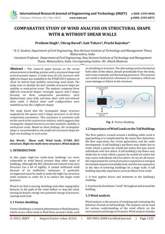
1.1 Vortex shedding
Vortexsheddingisacommonphenomenoninfluiddynamics, whichoccurswhenwindorfluidflowsaroundabody,such
asabuildingorstructure.Thealternatingvorticesformedon bothsidesoftheobject,detachperiodicallyfromthebody, andcreateunsteadyandfluctuatingpressures.Thisprocess canresultindestructivevibrationsorresonance,whichcan causedamageorfailuretothestructure.
Fig -1:Vortexshedding
1.2 Importance of Wind Loadson the TallBuildings
The flow pattern created around a building while wind is approachingitiscomplicatedbythemeanflowdistortion, the flow separation, the vortex generation, and the wake development.Atallbuilding'stopfloorsmayshakedueto wind, which a passer-by would not notice but may worry individualswholiveabove.Atallbuilding'stopfloorsmay shakeduetowind,whichapasser-bywouldnotnoticebut mayworryindividualswholiveabove.Asweareallaware, therequirementforverticalstructureexpansionisowingto thelimitedamountofavailableland,andthishasexposedus to the idea of towering buildings on a huge scale. A tall buildingtypicallyexperiencesseveraleffectsfromwind:
1. It first applies forces and moments to the building's cladding.
2.Itprimarilydistributes"wind"throughoutandaroundthe building.
1.3 Wind analysis
Windanalysisistheprocessofstudyingandevaluatingthe behaviorofwindontallbuildings.Theanalysiscanbeused for various understanding of the wind effects on the environmentanddesignofstructure.Windanalysisincludes
measuring and interpreting wind patterns such as wind direction,speedandeventomakeweatherpredictions.
Thereareactuallythreetypesofwindforcesthatwouldbe exertedonabuilding:
i) Uplift Wind Load is an upwards force of the wind that wouldaffectroofstructuresorsimilarhorizontalstructures in a building, such as canopies or awnings. The wind flow undera roofstructurepushestheroof upwards; thewind flowoverthehorizontalstructurepullstheroofupwards.
ii)ShearWindLoadisahorizontalpressureorforcethatcan causewallsor vertical structural elementstotilt orcrack, causingabuildingtotilt.
iii)LateralWindLoadisanotherhorizontalwindpressure that can make a structure move off its foundations or overturn.
1.4 Static and Dynamic wind pressure
Staticwindpressureisthetermusedtodescribetheforce thatwindexertsonastationaryobjectorstructure.Static wind pressure refers to the force exerted by wind on a stationarystructure,suchasabuilding.
Dynamic wind load gives rise to vertical motion, creating oscillations in any direction. Like the breaking of an overused violin string, oscillations are vibrations that can causeabridgetofail.
i)Storydriftreferstothelateraldisplacementofonestory orfloorofabuildingrelativetotheadjacentfloororstory duetowindloads.Inotherwords,storydriftmeasuresthe horizontalmovementbetweenadjacentfloorsofabuilding causedbywind-inducedlateralforces.
ii) Story displacement refers to the absolute horizontal movement of a building due to wind loads. It is the total distance that a building moves horizontally due to windinducedlateralforces.
iii) Baseshearreferstothelateralforcecreatedatthebase ofastructureduetowindloads.Itistheforcerequiredto keepthestructurefromslidingortopplingover.Thebase shear is proportional to the mass of the building and the accelerationcausedbythewind.
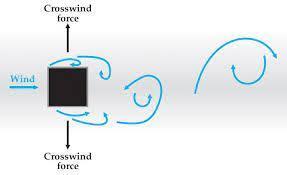
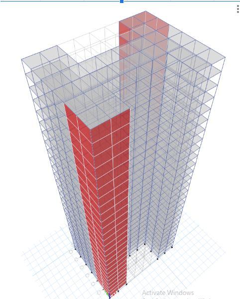
1.5 Shear wall
A shear wall is a structured element used in building constructionto resistlateral loadsuchasthosecausedby wind and earthquake or other external forces. A vertical platelikeareinforcedconcretewallstartingfromfoundation level andextendinguptothefull heightofthe buildingto formaverticalcantileveriscalledashearwall.
Itworksthebestwhentheyareplacedsymmetricallywithin oraroundabuilding'scentralaxispoint.Therearetwotypes ofalignmentforshearwalls:
Shearwallsalongtheperiphery: Shearwallsareprovided along the periphery if the possibility of twisting of the buildingisconsiderablyhigh.Thisneedsmorematerialfor construction.
Shearwallprovidedasacoretothebuilding,knownasshear core.Comparedtoperipheralshearwalls,shearcoreneeds less material and hence economical. But the shear core cannotresistthetwistingmomentinducedbywindloads.
Shearwallscanbeclassifiedonbasisofmaterialthatis usedandthevariousmaterialsusedforashearwallare:
Reinforcedconcreteshearwallsarewidelyusedshearwalls forresidentialbuildings.Thereinforcementisprovidedin bothhorizontalandverticaldirections.Butattheendofeach wall,barsarecloselyspacedandanchored.
Steel shear wall consists of a steel plate wall, boundary column and horizontal floor beam. The action of the steel shearwallismorelikeaplategirder.
2. DESCRIPTION OF ANALYTICAL MODEL
Inaddition,computer-basedsimulationsandmodellingtools areavailableandmayprovidemoreaccurateandefficient assessments of wind effects on objects, making them a preferablealternativetomanualmethods. DesigningaG+25 RCCframestructuremodelinE-tabsinvolvesseveralsteps, includingbuildinggeometry,materialproperties,member design, load application, analysis and results, design verification, final design, construction, and testing. E-tabs provide a powerful toolset for modelling and analyzing complex building structures and can help ensure that the finaldesignmeetstherequiredperformancecriteria.
Table-1: GeneralSpecificationofBuildingforETABs modelling:
Columnupto16th story
Column1 900x1100
Column2 700x1100
Column3 500x1000
Columnfrom16th to25th story
Column4 450x1000
Column5 400x900
Column6 300x700
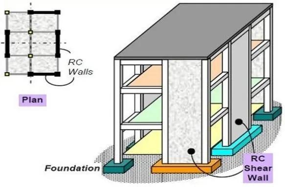
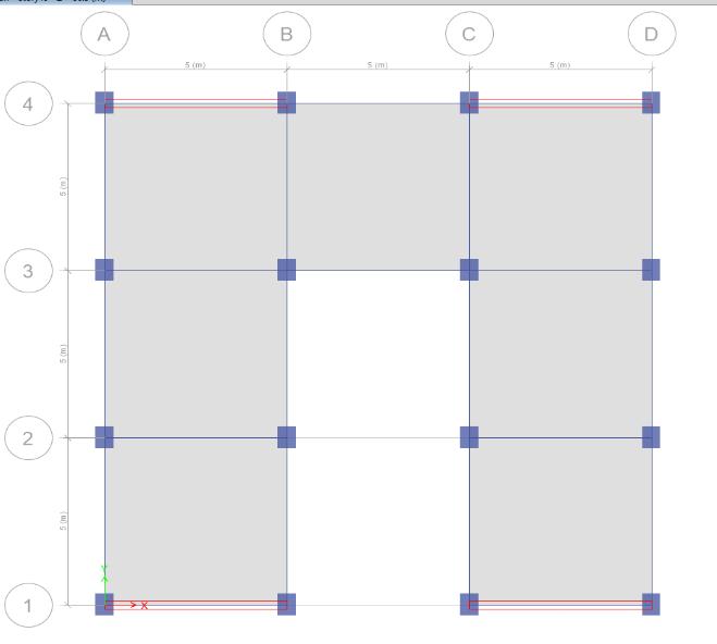
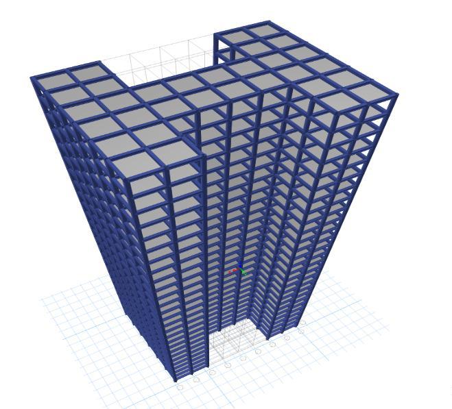
Step 1 -Modelling&AnalysisofRectangleShapedRCCModel ofG+25Storeys:
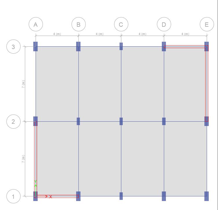
These are the general description of the analytical model thatcontentsgeneralspecificationofthestructureaboutits grade and density of steel and concrete, damping ratio, thicknessoftheshearwall,thicknessofwalls,andgeneral heightofthestructure.
This detail where used while modelling the structure in ETABSsoftwaretoobtaintheresultsoccurringbecauseof thewindactingonthestructure.
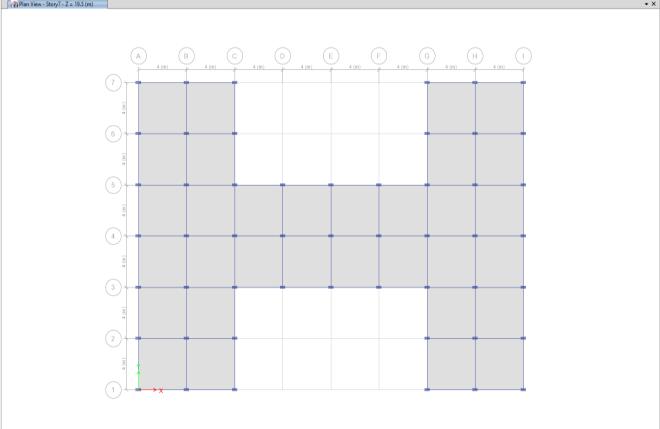
Table-2:
2DPlanviewofrectangularshapestructure
Winddesigncode IS875:1987(Part3)
RCCdesigncode IS456:2000
Steeldesigncode IS800:2007
Table-3:thefollowingtablerepresentsthedimensionof thebeamandreductioninthesizesofcolumn:-
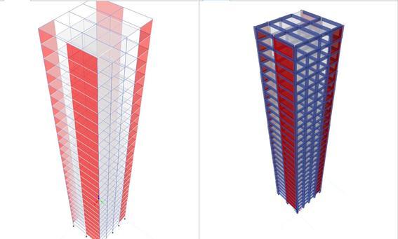
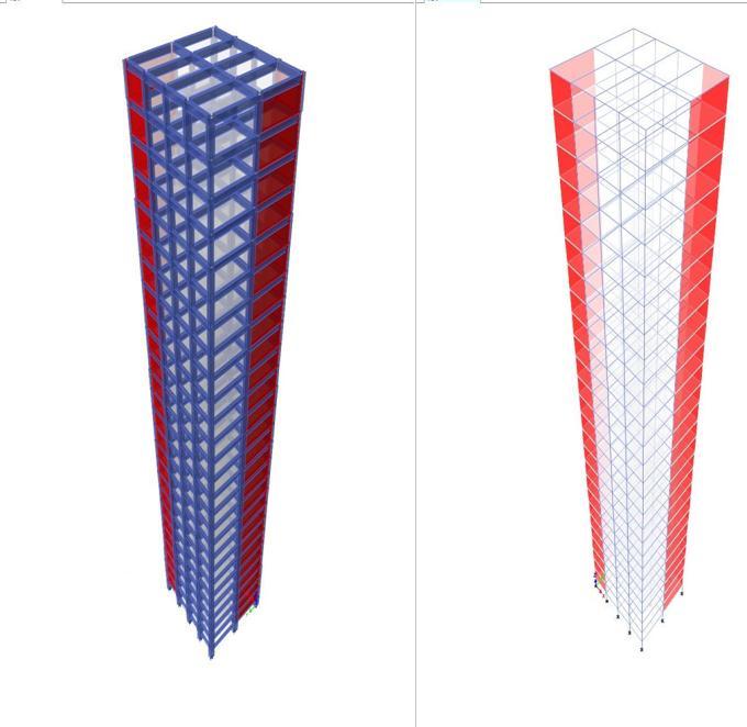
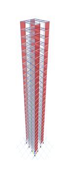
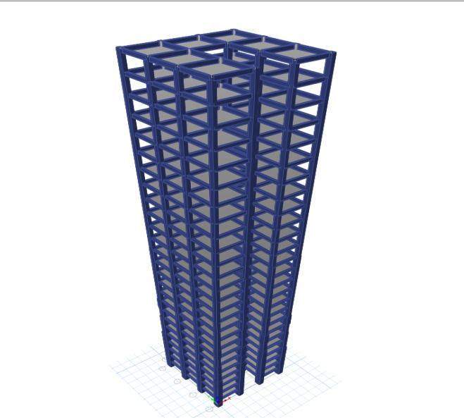
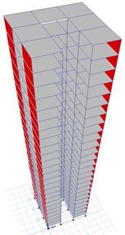
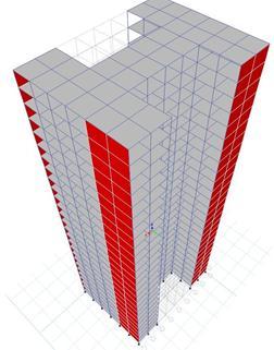
Case1:3Danalyticalmodelofrectangularshape Structurewithoutshearwall.
3. OBSERVATIONS
In total we have modelled and analyzed 3 cases for each shape,andthentosavecomplexityandtomaintainasimpler understanding only taken the minimum values from each casetocomparethemagainsteachother.
3.1. Results of story drift:
Chart -1:Storydrift
ThestorydriftoftheRectangleshapeisconsistentlylower than both H-shape and C-shape. The difference becomes moresignificantasthebuildinggetstaller.Forexample,at story25,thestorydriftfortheRectangleshapeis28%lower thantheH-shapeand58%lowerthantheC-shape.TheHshapeprovidesbettercontroloverbuildingswaythantheC-
shape. The difference becomes more significant as the buildinggetstaller.
3.2. Results of Base Shear Reactions
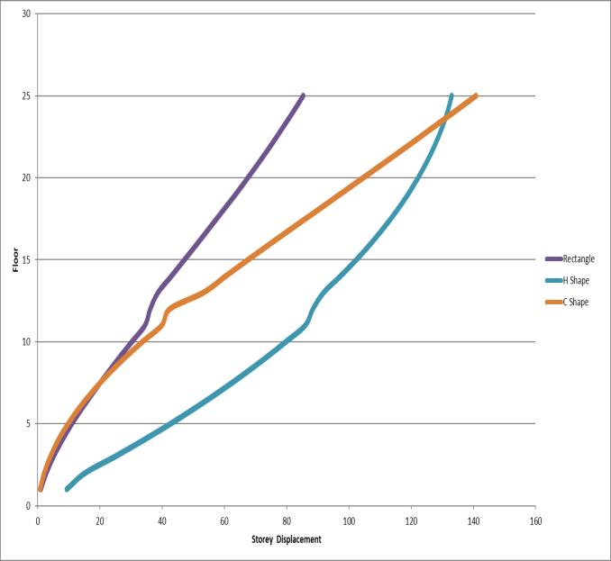
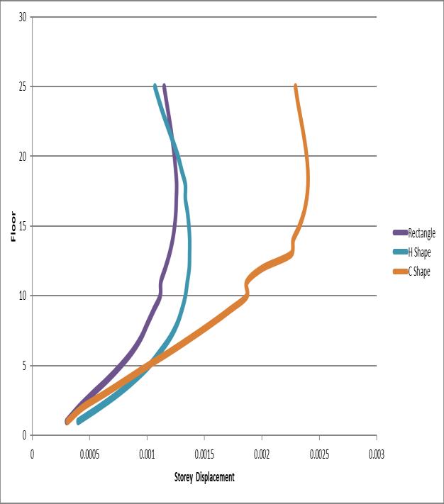
3.3. Results of story displacement
4. CONCLUSION
Displacement: RectanglemodelperformsbetterthanHand C shape models with % differences of 88% and 19% respectivelyatthehigheststory,indicatinghigherresistance tolateralloadsandlowerdisplacements.
Story Drift: Rectanglemodelexhibitsbetterresultsinstory driftthanHandCshapemodelswith%differencesof34% and21%respectivelyatthehigheststory,meaningitismore stableandcanresistlateralloadsbetter.
Base Reaction: Rectangle model outperforms L shape, T shape, and 4-way models in base reactions with % differencesof54%,54%,and46%respectivelyinFzand% differences of 59%, 47%, and 48% respectively in Mx, implyingitcanhandlehigherloadsandmomentsatthebase, makingitmorestable
Shear Wall:Rectanglemodelhasbettershearwalldesign efficiencythanothermodelsandrequirestheleastamount of shear walls to meet the target drift limits, leading to minimaluseofresourcesandmaterials.
Chart -2:StoryDisplacement
ThestorydriftoftheRectangleshapeisconsistentlylower than both H-shape and C-shape. The difference becomes moresignificantasthebuildinggetstaller.Forexample,at story25,thestorydriftfortheRectangleshapeis28%lower thantheH-shapeand58%lowerthantheC-shape.TheHshapeprovidesbettercontroloverbuildingswaythantheCshape. The difference becomes more significant as the buildinggetstaller
Cost-Effective: The rectangle model emerges as the most cost-effective option due to better performance with less materialusageandreducedconstructioncosts.
Overall,therectanglemodelisabetterchoiceforhigh-rise buildingdesignbasedonthe%differenceindisplacement, storydrift,basereaction,shearwalldesignefficiency,and cost-effectiveness.
REFERENCES
[1].T.Kijewski,A.Kareem,“Full-scalestudyofthebehavior of tall buildings under winds”, Health monitoring and
managementofCivilinfrastructuresystem,proceedingsof SPIEVol.4337(2001),PP441-450.
[2]. Yin Zhou, Ahsan Kareem, Ming GU, “Mode Shape CorrectionsforWindLoadEffects”,JournalofEngineering Mechanics(2002),PP15-23.
[3].YinZhouandTracyKijwski,“Along-windloadeffecton tall buildings: comparative study of major international codes and standards” (ASCE) 0733-9455, Vol.128, No.6, 2002,PP788.
[4].HoriaHanganandPooyanHashemi-Tari,“Modellingof high intensity winds” 18th analysis and computation specialtyconference(ASCE),2008.
[5]. Luisa Pagnini, “Reliability analysis of wind-excited structures”,(ELSEVIER),Vol.18,2010,PP1-9.