Free vibration investigation of thin plates under various circumstances using Finite Element Method
Kolugoori Veda Vyas1 , Muskan2 , Nalamadu Reethika31B-Tech, Department of Mechanical Engineering, JNTUHUCEJ, Jagitial, Telangana

2B-Tech, Department of Mechanical Engineering, JNTUHUCEJ, Jagitial, Telangana
3B-Tech, Department of Mechanical Engineering, JNTUHUCEJ, Jagitial, Telangana***
Abstract - Due to their strong resistance to shocks and vibrations, composite plates have found extensive use in a variety of engineering fields, including the aerospace, marine, and automotive industries. The vibratory behavior of thin plates has evolved into a significant and crucial factor that must be taken into consideration when designing structural elements because it is at the core of many issues that can destroy structures. The positions into which a structure will predictably be displaced are described by mode shapes. Structures cannot be considered safe based on their load-carrying capacity, but they should also be safe considering structural dynamic aspects. The offending mode is identified using modal analysis. This work explores the effect of material, laminate stacking sequence, geometry, and edge conditions on modal behavior. For the analysis, carbon-epoxy and T300/5208 graphite/epoxy composite materials are taken into consideration, and aluminum alloy is taken into consideration for isotropic plate simulations. To investigate how fiber orientation affects natural frequencies and associated mode shapes, the fiber angle is altered. The mode shapes and initial six natural frequencies are obtained. Based on the findings, a better boundary condition is suggested for applications with a narrow operating frequency range.
Key Words: Modal Analysis, Isotropic, Mode Shapes, Laminate Stacking Sequence, Fibre Orientations, Natural frequencies.
1.INTRODUCTION
Laminated composites are frequently employed in heavy industrial applications because of their physical and mechanical characteristics. Structures composed of composite materials are also referred to as smart structures since they may be developed to get different qualitiesinacontrolledway.Theexceptionalphysicaland mechanicalpropertiesofthesematerialsmakethemideal for engineering applications. Most engineering structures should pass the fundamental tests before being used in actual working conditions. Modal analysis, also known as vibrationanalysis,isoneoftheseprimarytests.
Several researchers have developed numerous solution methods in the last 20 years. Crawley calculated the natural frequencies and mode shapes of 8-ply
graphite/epoxy cantilever plates and shells with various laminates and aspect ratios using experimental and theoretical analysis. There was limited agreement about frequencies, however, there was a great agreement between the observed and predicted mode shapes[1]. A couple of 12-employ graphite/epoxy plates' regular frequencies and mode states were provisionally and conceptuallyresolvedbyAndersonandothers.Thecrossply, quasi-isotropic, and 15°–30° plate layouts were evaluated. Each layup was tested in three distinct ways: cantilever, free-hanging, and fixed-fixed[2]. Analytically, Barai, and Durvasula investigated how the vibration and buckling characteristics of curved panels made of hybrid laminateswereaffectedbytheaspectratio,curvature,ply orientation, and stacking sequence. They concluded that the natural frequencies, which are more common on thin plates,areenhanced bycurvature[3].Rajeshkumar and V. Hariharan also examined the effects of fiber orientations rangingfrom0to90andaspectratiosrangingfrom45to 120 under various boundary conditions in their paper[4] To analyze free vibrations on composite laminates and learn more about their vibrational characteristics, Kamal and colleagues employed the Rayleigh-Ritz energy technique, layered, composite plate theory, and modified sheardeformation[5].Thenaturalfrequencyanddamping characteristics of different S-glass, carbon, and Kevlar fiber combinations were studied by Erkling et al. The numerical outcomes for completely fixed conditions are evaluatedagainstpreviously releasedfindings.Combining fixed (C), simply supported (SS), and free(F) boundary conditions, they investigated hybrid composites. They demonstrated that the highest and lowest recurrence values occurred individually in the CFCF and CFFF edge situations. To analyze the static and free vibration characteristics of shear deformable thin and thick laminatedcompositeplates[6].Daietal.developedameshfree approach by using higher-order shear deformation theory. To successfully enforce necessary boundary conditions to produce natural frequency and static deflection, the penalty approach was applied. Studies presented on the frequency vibration characteristics of hybrid laminates are less in-depth according to the literaturethatiscurrentlyaccessible[7]
Analytical techniques formed the foundation of many studies. Literature. Our goal is to investigate how the
natural frequenciesoflaminatesare affected by the order inwhichvariouslayersofcompositeplatesarelaminated. The plates were put through a simulation of a quasiisotropic stacking sequence made up of layers with fiber orientations of 0°, 30°, 60°, and 90°. The results of the investigation into the impact of the inner layers' orientationonnaturalfrequenciesarethenpresented.

3. FINITE ELEMENT ANALYSIS
Carbon/epoxy composite plates are thought of with one endasfixedtoperformthe modalanalysisandobtainthe first five mode shapes. Each ply of the four laminates under consideration has a thickness of 2.5mm (about 0.1 in) and is rectangular. Using a T300 composite and aluminum alloy plate with all edges simply supported, an FEAwasalsoconductedtofurtherexaminetheimpactofa material change. The software's database contains informationaboutthepropertiesofaluminumalloy.Table 1 lists the material characteristics of the T300/502 graphite/epoxy composite, carbon/epoxy composite material,andaluminumalloy.
Fig
a)CFFFb)SSSSandc)CCCC
Additionally, finite element analysis was used to investigate how hybridization affected modal frequencies. Toconductthestudy,carbonepoxycompositeplateswith laminatingstackingsequencesof[0/0/0/0],[0/30/30/0], [0/60/60/0], and [0/90/90/0] under various boundary conditionswereused.
Carbon/epoxy composite plates of p=2m length, q=1m width,andt=10mmthickness(PlateA)andp=4mlength, q=1m width, and t=10 mm (Plate B) is used for the investigationofaspectratioonnaturalfrequency.
With the aid of ANSYS and the ACP(Pre) design modeler, twoplatesweremodeled.
Table1.Analyzedpropertiesofthematerial
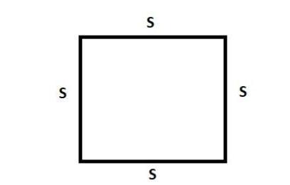
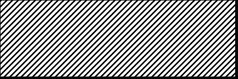
AsshowninFig.1,cantileverboundaryconditions,suchas clampedat one end (CFFF),all sidesclamped(CCCC),and simply supported (SSSS), were examined for laminated composite plates. This allowed us to investigate how boundarycircumstancesaffectnaturalfrequencies.where,
C:Clamped;F:Freeend;S:Simplysupported.
Aplatewitha1mdimensionwasfixedtotheedge.
4. RESULTS
Finding mode shapes and examining the impact of boundaryconditions,laminatestackingorder,aspectratio, and material on the natural frequencies were the objectivesofthiswork..
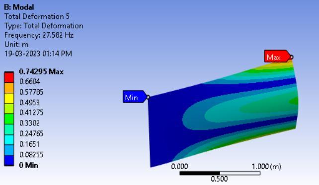
4.1. Mode shapes:
A four-layer laminated plate made of carbon epoxy composite underwent numerical simulations with [0/0/0/0] ply orientation and under cantilever condition i.e,CFFF boundarycondition.Thefiguredepictsthe mode forms corresponding to the frequency of the boundary conditionsmentionedpreviously.
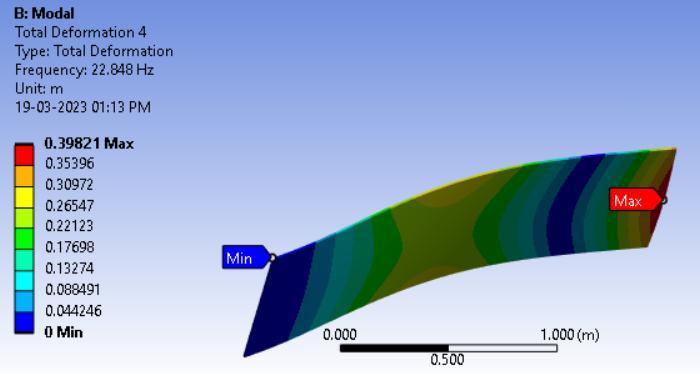
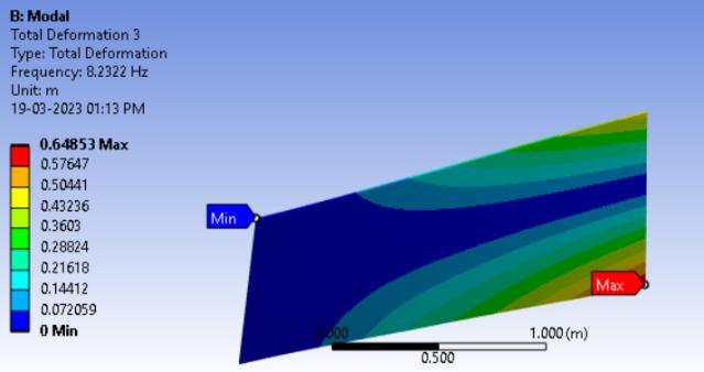
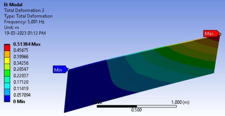
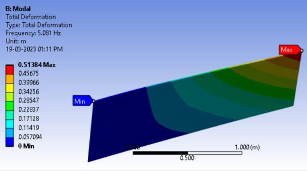
Fig3.Modeshapesforarectangularcross-ply (0°/0°/0°/0°)platefortheboundaryconditionCFFF
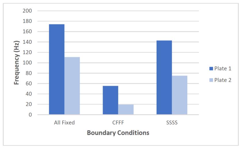
4.2. Effect of Boundary Conditions on Natural Frequencies:
Three border-related situations CCCC, CFFF, and SSSS are considered for the simulation of carbon epoxy composite plates of dimensions 2m X 1m X 10mm and fiber orientation[0/90/90/0]. Theresultsclearlyshowthatthe all-fixed boundary condition, which has noticeably higher natural frequencies than other boundary conditions, is best suited for situations where the operating frequency rangeisbroad.Thenaturalfrequencieswerevariedas,
4.3. Effect of
The rectangular carbon epoxy composite plate's ply orientation for varied boundary conditions. A two-meterlong rectangular carbon epoxy composite plate was analyzed for several fiber orientations, including [0/0/0/0], [0/30/30/0], [0/60/60/0], and [0/90/90/0]. Theresultsareshownbelow,
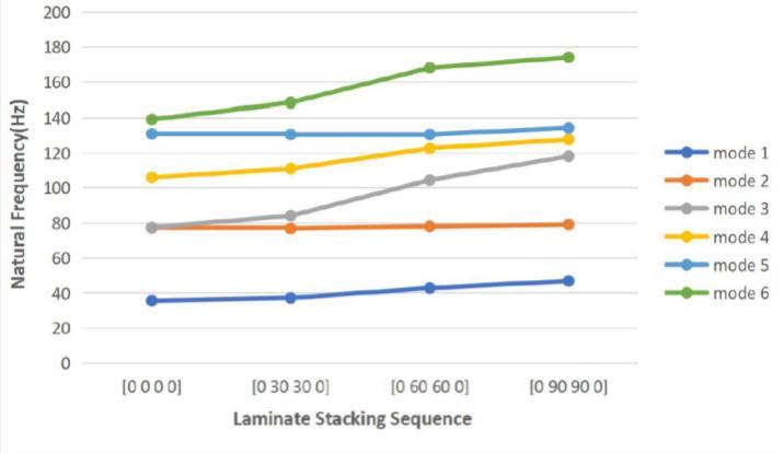
4.3.1.All
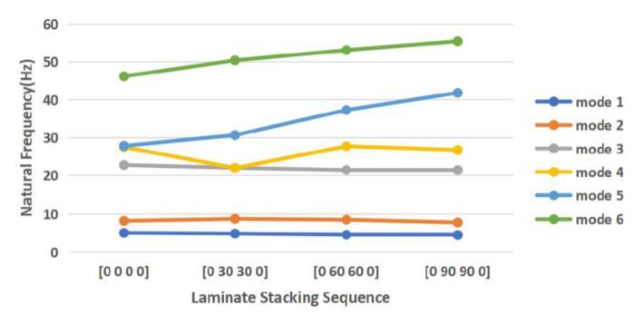
Fig5.Variationoffirstsixnaturalfrequencieswithrespect toorientationsforcarbonepoxyplates(CFFF)
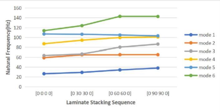
4.3.3. Simply supported (SSSS):
respect toorientationsforcarbonepoxyplates(CCCC)
4.3.2. Cantilever Condition (CFFF):
Fig
Variationoffirstsixnaturalfrequencieswithrespect toorientationsforcarbonepoxyplates(SSSS)
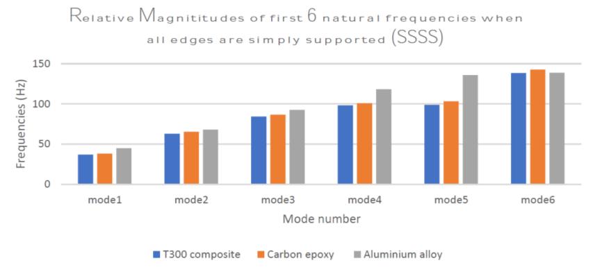
4.4. Effect of Material:
For investigating the effect of material, three materials with the same orientations [0 90 90 0] and when simply supported on all sides (SSSS) are used. The results are displayedinatableandcomparedusingagraph
4.5. Effect of Aspect Ratio on Modal Frequency Values:
Byconsideringthetwoplateswithdimensionsof2mX1m and4mX1m,thetopicofthestudywasextendedtobetter understand how the length-to-breadth ratio affects the vibrationpropertiesoflaminatedcompositeplates.
Fig8.VariationsofNaturalFrequencieswithAspectRatio Table 7 lists the outcomes that were obtained. It is clear from Tables 7 and figure 8 that raising the aspect ratio of the plate significantly decreased the system's natural frequencyinallthreeboundaryconditions.
5. CONCLUSIONS
In the current work, laminated composite modal analysis is carried out using FEA. The impact of fiber orientation, material type, and boundary conditions on the natural frequencyofthecompositeplateisinvestigated.Themain lessonsdrawnfromthisresearchare:
1. Under various boundary conditions the first six natural frequenciesareproduced.
2. Compared to the CFFF and SSSS boundary conditions, the CCCC boundary condition has much higher natural frequencies, making it best suited for applications with a wideoperatingfrequencyrange.
3. The effects of fiber orientation on the natural frequenciesofvibrationofcompositelaminatedplatesare analyzed under varied boundary conditions. The natural frequency rises as the fiber angle for the inner layers' increases.
4.Adecreaseinthenaturalfrequencyvaluesoccurswhen the length of the plate is increased without changing the otherdimensions.
5. Aluminum plates are found to have greater natural frequencies than composites. Comparing carbon epoxy plates to T300 graphite/epoxy plates, the natural frequenciesofcarbonepoxyplatesaregreater.
6.REFERENCES
1. Crawley E.F. The Natural Modes of Graphite/Epoxy Cantilever Plates and Shells Journal of Composite Materials.,13,(1979),195-205.
2.Anderson T.J. and Nayfeh A.H, J.Vibration and Control, 2 (1996),381-414.
3.Barai A. and Durvasula S.Vibration and buckling of hybrid laminated curved panels. Composite structures 21 (1991),15-27.
4.G.Rajeshkumar and V.Hariharan. Free vibration analysis of hybrid-composite beams. International conference on advancesinengineeringscienceandmanagement,pp.97881,2012
5.Kamal K. and Durvasula S. Study of Free Vibration of composite Laminates, Composite. Structures. 5 (1986), 177-202.
6.ErklingA,BulutM,andYeterE.,Sci.Eng.Compos.Mater. 22(2014),565-571.
7.Dai,K.Y.,G.R.Liu,K.M.Lim,andX.L.Chen."Amesh-free method for static and free vibration analysis of shear deformablelaminatedcompositeplates."JournalofSound andVibration269,no.3-5(2004):633-652.
7.AUTHORS
First Author – Kolugoori Veda Vyas, B-Tech, Department ofMechanicalEngineering,JNTUHUCEJ,Jagitial,Telangana.
Second Author – Muskan, B-Tech, Department of MechanicalEngineering,JNTUHUCEJ,Jagitial,Telangana.
Third Author - Nalamadu Reethika, B-Tech, Department of Mechanical Engineering, JNTUHUCEJ, Jagitial, Telangana