Improved Nine-Level Transformerless Inverter with Reduced Part Count
Mohar singh meena, Neeraj kumawat, Dheeraj VermaStudent YIT jaipur

Assistant professor Department of Electrical engineering Research Scholar (Ph.D. Student, Department of Electrical Engineering, Malviya National Institute of Technology, Jaipur, Rajasthan, India.)
Abstract - An PV inverter systems improve in terms of efficiency using transformerless inverter topologies but newproblemrelatedtoGalvanicisolationneedtobedealt with it. The electrical unit provides galvanic isolation and eliminatesleakagecurrent, thuspreventingdirectcurrent from entering the network. The main disadvantage of usinga transformer isthatitsignificantlyreducestheIt o ered a transformer-free connection that is cost- effective, space-saving, and more energy efficient. When galvanic insulationisrestoredinatransformerless connection,the leakagecurrentincreasesandthereforethePWMmethods andtopologiesused
Key Words: transformerless inverter, multilevel, leakage current.…
1. INTRODUCTION
Among all green resources, solar electrical energy (PV) is one of the cleanest, quickest, and most widely available energy sources.Thecost of thePVsystemiscontinuously falling thanks to technological advances in manufacturing processes and materials, making it the most economical energy source for large-scale planning in the future. Throughtheirincreaseduseofgreenenergy,a numberof nations (including the USA, Germany, China, Japan, Australia,France,Italy,Spain,etc.)havealreadystartedto reap the benefits. In the Asian country, the market for renewable energy may expand quickly. As of the end of February2020,thenationhadatotalinstalledcapacityof 34.404GW
for solar energy. A twenty GW capability goal set by the Indian government for 2022 was met four years earlier thananticipated.ToconnectthePVpanelstothegrid, the grid-connectedPVsystemsrequirepowerinverters,which are typically Galvanic isolated and non-isolated inverters are two different classifications. Galvanic isolation is typically achieved in the isolated type using a highfrequencyDCsidetransformeroralow-frequencyACside electrical device, which increases system safety overall. Transformerless inverters have attracted a lot of interest fromthedomesticmarketbecauseoftheirlowtomedium power capacity cost [1], size/weight, and increased efficiency
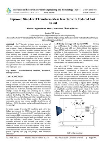
1.1 H Bridge topology with bipolar PWM Having two half-bridges, the H-bridge is a fundamental topology. Motor drives and UPS have both utilized this topology. SeveralPWMtechniquescanbeappliedtocontrolthefour switches in this arrangement. The simplest is a bipolar PWM, which modulates the extra switches in relation to one another and generates an output voltage with two levels(+Vand-V).Thelinecurrentmakesitswaybackto the DC link capacitor during the freewheeling phase, whichlowerstheconversionefficiency.
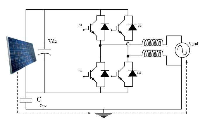
If we select the FFT for this design, we can see that there are significant voltage spikes that result in parasitic capacitances. Consequently, a significant amount of leakage current. Since the solar generator's parasitic capacitance controls the leakage current in this instance, the leakage current cannot be influenced by the output filter.TheH-bridgewithbipolarmodulation,havingaline filterwithinductancesevenlydistributedbetweentheline and the neutral, and having a bipolar PWM strategy ensuresconstantcommonmodevoltage,whilePVground voltageonlyvariesasafunctionofgrid[9]frequencywith an amplitude equal to half the peak value of the mains voltage. This makes it suitable for photovoltaic systems without a transformer. Conversion efficiency is the only limitation,aswaspreviouslymentioned.
Halfbridgetopology
HERIC TOPOLOGY
The computer system combines all of the benefits of unipolar PWM with common-mode behaviour in bipolar PWM,anditalsooffershighefficiency.
The idea of a highly efficient and dependable inverter (HERIC) has changed the topology of the H-bridge, as previouslymentioned[18].A diode connects eachseries of 2extra switches(S5-S6)thatarepartofthealteration. As illustrated in figure the photoelectric generator is detached from the network over the full zero voltage vector when S5, S6, or ar glows while S1, S2, S3, and 4 hundredths are all in their off states. Because the switchingfrequencywillnotbethehigh-frequencychange occurring on the DC terminals, an interruption occurs in the construction of the zero-voltage vector, resulting in a unipolar output voltage with an equivalent frequency. photoelectric power plant. Additionally, the inverter efficiency stays high because, depending on the direction of the mains current, the load current short circuits throughS5orS6duringthefreewheelingperiod.
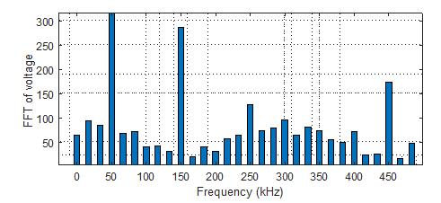
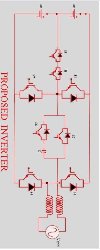
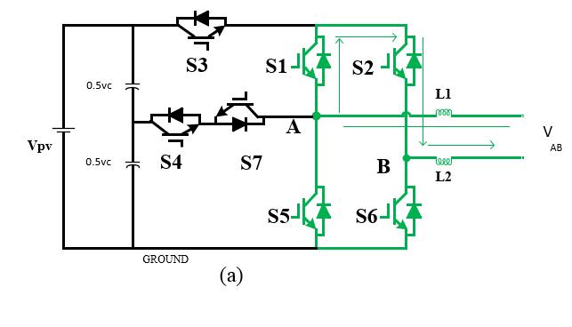
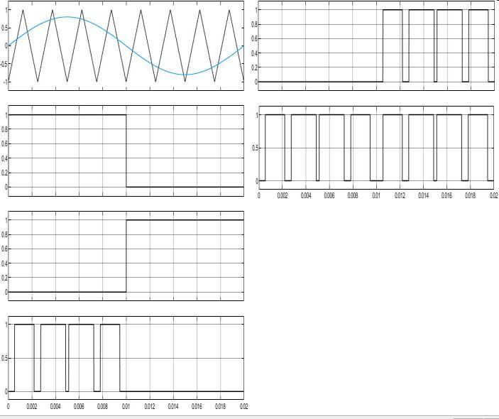
Fig 1 displays the circuit schematic for the suggested inverter topology. There are seven MOSFET switches in total: S1, S2, S3, S4, S5, S6, and S7. HSPWM, or hybrid sinusoidalPWM,isthemodulationmethodemployed.Vpv isarepresentationofaphotovoltaicpanel.Forfiltering,an L-Lfilterisemployed.Theelectricalgridisrepresentedby Vgrid.TheinputdclinkcapacitanceisrepresentedbyCin and is divided into two equally sized components by c pv
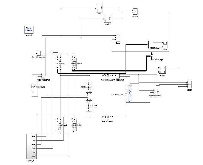
2. PV grid-tied systems can link the suggested inverter design, which can lower [2] leakage currents by maintaining consistent common mode voltages. Because they use transformers, traditional half-bridge inverter topologies do not require a fixed common mode voltage. Transformer omission results in a galvanic connection betweenthegridandthesolarpanels.
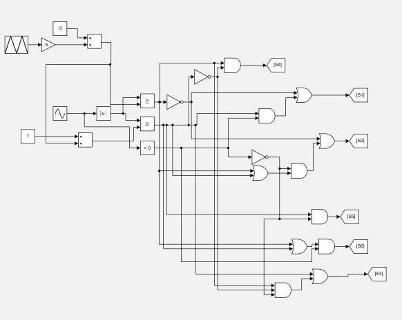
1.2 Switching Table
Sample paragraph, The entire document should be in cambria font. Type 3 fonts must not be used. Other font types may be used if needed for special purposes. The entire document should be in cambria font. Type 3 fonts mustnotbeused. Otherfonttypesmaybeusedifneeded forspecialpurposes.
operational description
Common mode voltage causes leakage current to terminate directly. Leakage current will be kept to a minimum [3] if we keep the common mode voltage constant. In general current in a capacitor is defined by =cd(constant)/dt=0
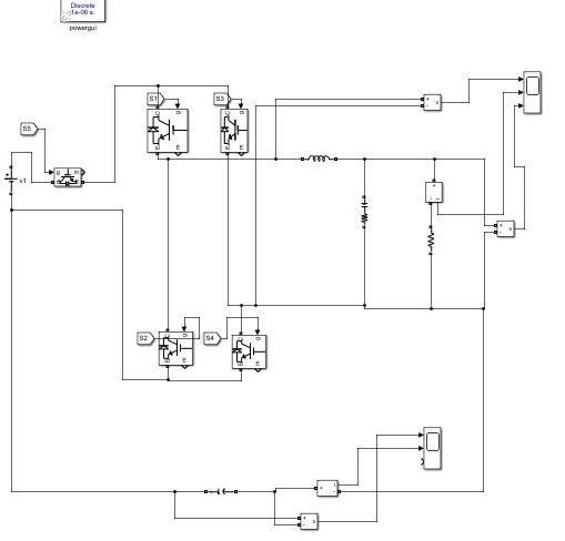
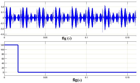
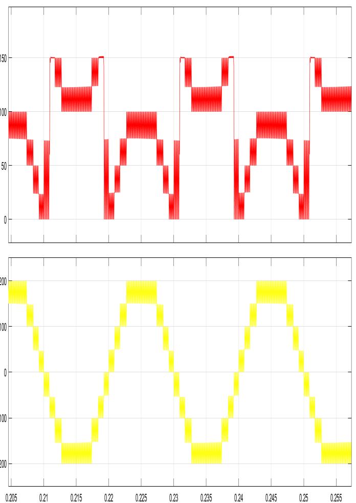
Ihave taken resistiveloadinsimulation.I’veutilised400 vdc.I’vegottwo outputshere. whichis figure iiidisplays theterminal outputofmyinverter without a filterand fig displaystheoutputoftheinverterwithaninductoracting asthefilter.
I used 300 nf capacitors and 3 mh inductors, and the output of the inverter with the filter is only sinusoidal. Withoutthefilter,theoutputisNine stepped waveforms. Levels with steps are. Matlab Simulink model is the simulationplatformofchoice.

3. CONCLUSIONS
An inverter may be used to feed the alternative energy to the grid. The topologies of inverters with and without galvanic isolation are completely different from conventional inverter. different transformerless inverter topologies are used for analysis, design, and simulation
purposesduringthiswork,firstIhaveusedH-5topology, and then H-6 topology, at last I have simulate proposed topology Results that meet the objectives are measured after simulating the circuit. Simulated experiments are alsousedtotesttheleakagecurrent.Igotleakagecurrent in permissible limits.in my model I got leakage current 4 microampere.
REFERENCES
[1] Islam,Monirul,SaadMekhilef,andMahamudulHasan. "Single phase transformerless inverter topologies for grid-tied photovoltaic system: A review." Renewable and sustainable energy reviews 45(2015):69-86.
[2] Islam,Monirul,SaadMekhilef,andMahamudulHasan. "Single phase transformerless inverter topologies for grid-tied photovoltaic system: A review." Renewable and sustainable energy reviews 45(2015):69-86.
[3] Araújo, Samuel Vasconcelos, Peter Zacharias, and Regine Mallwitz. "Highly efficient single-phase transformerless inverters for grid-connected photovoltaic systems." IEEE Transactions on Industrial Electronics 57.9(2009):3118-3128.
[4] Zeb, Kamran, et al. "A review on recent advances and future trends of transformerless inverter structures for single-phase grid-connected photovoltaic systems." Energies 11.8(2018):1968.
[5] Yang, Bo, et al. "Improved transformerless inverter with common-mode leakage current elimination for a photovoltaic grid-connected power system." IEEE transactions on power electronics 27.2 (2011): 752762.
[6] Gu, Bin, et al. "High reliability and efficiency singlephase transformerless inverter for grid-connected photovoltaic systems." IEEE Transactions on Power Electronics 28.5(2012):2235-2245.
[7] Zeb, Kamran, et al. "A review on recent advances and future trends of transformerless inverter structures for single-phase grid-connected photovoltaic systems." Energies 11.8(2018):1968.
[8] Yang, Bo, et al. "Improved transformerless inverter with common-mode leakage current elimination for a photovoltaic grid-connected power system." IEEE transactions on power electronics 27.2 (2011): 752762.
[9] Siwakoti, Yam P., and Frede Blaabjerg. "Commonground-type transformerless inverters for singlephase solar photovoltaic systems." IEEE Transactions on Industrial Electronics 65.3(2017):2100-2111.
[10] Ardashir, Jaber Fallah, et al. "A single-phase transformerless inverter with charge pump circuit concept for grid-tied PV applications." IEEE Transactions on Industrial Electronics 64.7 (2016): 5403-5415.