Protection of 3-Phase Induction Motor Fed from 3-Phase Inverter Using Rogowski Coil Transducer
Basma Mahmoud1 , Elwy Eissa El Kholy2 , Hossam Youssef Hegazy3 , Tamer A.A.Ismail41 Faculty of Technology and Education, Helwan University, Egypt,

2 Engineering Department, Faculty of Engineering, Menoufia University, Egypt,
3 Faculty of Technology and Education, Helwan University, Egypt,
4 Faculty of Technology and Education, Helwan University, Egypt, ***
Abstract - This study presents a technique for protecting a field-oriented control (FOC) system using a Rogowskicoil. The proposed method depends on measureing the current that pass through switches inverter (IGBTs) using a Rogowski coil to protect switches for over current. This technique describes the theory and design of Rogowski coil ,as well as the Rogowski coil protection of IGBTs. The obtained experimental results give another evidence for the validity and efficacy of the proposed Rogowski coil design in protecting the system from high impulse currents An evaluation of the proposed measurement process was theoretically carried out using power simulation program (PSIM).
Key Words: induction motor (IM);Field oriented control (FOC); Rogowski coil; current transducer
1. INTRODUCTION
Induction motors are pre ferred for most of the industryapplicationsduetothelimitationsofcommutation and rotor speed in DC drives. The induction motor is brushlessandmaybecontrolledusingsimplewaysthatdo notrequireashaftpositiontransducer.Becausethereisno shaftpositionfeedback,themotorisonlystableiftheload torque does not exceed the breakdown torque. It is conceivable for oscillatory instabilities to occur at low speeds Tosolvetheseconstraints,field-orientedorvector control has been developed, in which the phase and amplitude of stator currents are adjusted in order to maintaintheoptimal anglebetween statormmfandrotor flux This control works by converting a three-phase time andfrequencydependentsystemintoatwo-coordinate(d andqaxis)timeinvariantsystem.Theseprojectionsresultin a configuration that resembles that of an independently stimulatedDCmotorcontrol.Fieldorientation,ontheother hand,necessitatestheuseofeitherashaftpositionencoder or an in-built control model with motor-specific characteristics In general, there are two types of field orientedcontrolmethods.1.Field-orienteddirectcontrol2. Controlofanindirectfield.
The field Oriented Control was previously developed for high-performance motor applications that must work smoothlyoverthewholespeedrange,generatefulltorqueat
zerospeed,andhavegreatdynamicperformanceincluding quickaccelerationandstopping.Nevertheless,duetoFOC's advantage in motor size, cost, and power consumption discount [7],[4], it is becoming increasingly appealing for lower performance applications as well. The downside of this system (FOC) is the lack of a protective mechanism againstovercurrentduetomistakes,hencetheRogowskicoil isrecommendedasthebestsolutionforthisproblem.The Rogowski coil is the ideal choice for high current measurementinhigh-powerlaboratoriesbecauseitishighly reliableasacurrentsensorforpowersystemprotectionand monitoring [10]. Walter Rogowski invented it in the nineteenth century, and it is still frequently utilised in a variety of applications today. Some applications include measurementsofpulsedandimpulsivecurrents[7],power frequencycurrent,andmonitoringofinsulatedgatebi-polar transistors (IGBTs), diodes, and capacitors in power electronic converters The Rogowski coil is widely used becauseofitsbenefitsoverothermeasurementdevicessuch as current transformers (CTs). Because there is no core saturation,theRogowskicoiloffersthebenefitoflinearity. As a result, it is made of turns twisted around a nonmagneticcore.Itisgenerallyunderstoodthatcoresaturation is a significant drawback in CTs, causing difficulties in determiningfaultdistancesinelectricpowersystemswhen utilised with distance protection relays [6], [8]. Further advantages of Rogowski coils over CTs are their small weight,lowcost,anddecreasedsize[8].
In fact, the design of the Rogowski coil has piqued the curiosity of many experts in recent years. As a result, the Rogowskicoildesignistailoredtoaspecificpurpose.Oneof thesebreakthroughsisthedesignofaPrintedCircuitBoard (PCB) Rogowski coil [18]-[21]. As a result, to be more appropriate for such applications, a PCB Rogowski coil is builttomonitorcurrentsforIGBTsandcapacitorsofpower electronic converters [15], [16]. To monitor currents through a switch inverter (IGBT), typical Rogowski coils shouldbeutilised.
To measure current through a switch inverter (IGBT), a typical Rogowski coil should be utilised. As indicated in Figure 1, each coil is wrapped around the switch inverter wherethecurrentistobemeasured.Inreality,protecting
switchinginvertersintroducesotherchallenges,suchasthe expensive cost of protective equipment. Also, it cannot sustain indefinite short-circuit currents. Hence, in our research,wepresent a low-costRogowskicoildesignthat may be utilised to detect currents across switches inveter withouttheneedforcostlysensingdevices Additionally,the samecoilmaybeusedtomeasurecurrentsrangingfromfew amps to hundreds of kiloamps. Rogowski coils do not measuredirectcurrents,butunlikeCTs,theycanaccurately measurecurrentswhenalargedccomponentispresent,can be used to measure current distributions in circuits with verysmallimpedanceswithoutaffectingthecircuits,andcan beverysmalltomeasurecurrentsinrestrictedareaswhere other techniques cannot be used. It is so tiny that it can monitorcurrentsinplaceswhereotherapproachescannot be employed. It is so tiny that it can monitor currents in placeswhereotherapproachescannotbeemployed.
In this paper, We present a Rogowski coil design for monitoringcurrentsacrossswitchinginverters(IGBTs).The Rogowskicoilismadeupofdifferentcoilstwistedarounda circular non-magnetic core. A current reconstruction approachformeasuringcurrentsusingIGBTsispresented. TheinducedEMFsofRogowskicoilswheninstalledaround IGBTsareusedinthecurrentreconstructionapproach.The proposed Rogowski coil design, as well as the existing reconstructionapproach,aretheoreticallyvalidatedinterms of accuracy and efficacy. PSIM software was used to implementtheRogowskicoilandthecurrentreconstruction approach.
Also,theprincipleofoperationincurrentmeasurementand Protectionofswitchesinverter(IGBTs)areexplained.
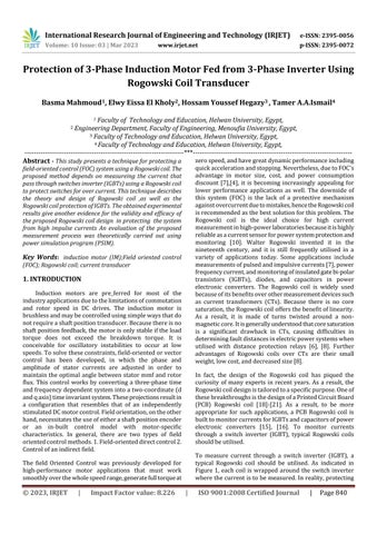
2.1 Rogowski coil Basics
Figure2showsaRogowskicoilcoiledaroundaconductor. The equation for the current that flows through the conductoris:
(1)
Wherei(t) denotesthe instantaneous current in A,Imthe currentamplitudeinA,wtheangularfrequencyinrad/sec, isthephaseangleinrad,andtthetimeinsec.
2. Protection of IGBTs Using Rogowski Coil

In this section, Rogowski coil Basics is introduced .In additointo, EquivalentcircuitofRogowskicoilispresented.
WhenaRogowskicoilisputonacurrent-carryingwire,it creates a voltage ine proportional to the coil's mutual inductanceMand the current , asshownbyequations(2):
where ine representstheinducedEMFinthecoil(V)andM representsthemutualinductance(H).Asaresult,thecoil's equivalent circuit, as described in several studies in the literature, depicts the coil with the equivalent circuit depictedinFigure3. Hence, equations(3)maybeused to representtheinducedEMFatthecoilterminals: (3)
Indeed,theamplitudeandphaseangleoftheoutputvoltage atthecoilterminalsvariesfromtheinducedEMF,especially athigherfrequencies.Thisisbecauseofthecombinedeffects ofcoilself-inductance(Lc),coilresistance(Rc),andcoilstray capacitance(Co).Equations(4)canbeusedtorepresentthe outputvoltageatthecoilterminals:
From equation (3), the current is derived using the relationship
Where isthecurrentpassingthroughtheRogowskicoil winding. Substituting (2) into (4), the induced EMF can be computedfrom:
2.2 Protection of IGBTs
Figure2depictsacontrolcircuitthatemploysaRogowski coil to safeguard the FOC system from excessive currents that might cause system damage. Consider the distorted current going through the conductor in figure 4 to clearly explaintheselectedcurrentreconstructionapproach Hence, whencurrentpassingthroughtheconductorinducesanEMF inthecoilandavoltageatitsterminals.Therefore,through terminals of Rogowski coil we can measure Root main squarevalue(RMS)oftheoutputvoltage,where(Vrms)is usedasanexpressionofthecurrent.Hence,fed(Vrms)into the comparator block to compare the actual value of the voltage and reference value, the error signal from this projection feds NOT Gate , so if the output gate is one. It meansthattheactualvalueislowerthenthereferencevalue, thus the Field Oriented control system continues to work normally,butifthegateoutputiszero,itmeansthatthereis a high in current, so the control circuit will separate the pulsesGatesswitchesinverter.
3.Simulation and Analysis
The power simulation programme (PSIM) was utilised to conceptually validate the suggested measuring technique. TheRogowskicoilwasmodelledusingtheanalogouscircuit depictedinFigure3andtheaccompanyingequations(2)and (3).(6).
The whole FOC system simulation model, and the parametersofinductionmotoraretabulatedinTableII.
PARAMETERSOFSIMULATEDTHREE-PHASEINDUCTION
Thesimulationexaminationwascarriedouttovalidatethe correctness of the drive system's control strategy. The findingswereobtainedatvariousoperatingpoints,including drive responsiveness due to load variations and speed command step adjustments. Figure 6 depicts three-phase current.Figure7depictsthewaveformsofthemotorphase and current. Figure 8 depicts the 1.5-second step shift in speedfrom1000rpmto800rpm.Itisdemonstratedthatthe rotoris smoothlyacceleratedto obey the speed reference command with virtually zero steady state error Figure 9 depicts the torque created by the motor. The torque increasesanddecreasesinproportiontothestepvariations inthereferencespeedcausedbythedynamicstates.
Fig.10. Simulation drive response for FOC with Rogowski coil at full load: Fig.10 shows speed response at 0.3s the speed changes from 1000 to zero cause high current circuit,wherefore thecontrolcircuitfortheRogowskicoil disconnects the system due to high current occurrence greater then reference current.The torque response showninFig.11.at0.3s,the torqueincreaseanddecrease during the change decrease speed due to the dynamic states. Fig.12 shows the motor phase current . the control cicuit will continue to provide IGBT gate pulses from 0-0.3s,but at 0.34s,the pulses will be disconnected fromthegates,asshowninFig.13
To detect power frequency AC currents, a measurement approachbasedontheusageofaRogowskicoilwithafield oriented control system is proposed. PSIM software was used to conceptually assess the suggested measuring technique. The proposed measurement process's efficacy wasthusvalidated.Ingeneral,itispossibletoconcludefrom thisresearchthatRogowskicoilsarefrequentlyemployed forprotection.IthasbeendemonstratedthattheRogowski coil has a high capability for high current measuring or sensorsuchasfaultcurrentdetection,highimpulsecurrent detection, and so on. Furthermore, the modelling findings reveal that the Rogowski coil is well suited to the system (Foc).
REFERENCES
[1] Popescu M., Induction Motor Modelling for Vector Control Purposes, Helsinki University of Technology, LaboratoryofElectromechanics,Report,Espoo2000.
[2] M. A. Hannan, J. A. Ali, M. Azah and A. Hussain, "Optimization techniques to enhance the performance of induction motor drives: A review," Renewable and Sustainable Energy Reviews, vol. 81, no. 2, pp. 1611-1626, 2018.
[3]M.Suetake,I.N.daSilva,andA.Goedtel,"EmbeddedDSPBased Compact Fuzzy System and Its Application for Induction-Motor V/fSpeed Control," IEEE Transactions on Industrial Electronics, vol.58,no.3,pp.750-760,2011.
[4]Hannakam,L.,“Dynamicmodellingofinductionmachine onananaloguecomputer”,Regelungstechnik,1959.
[5]Blaschke,F.,“Theprincipleoffieldorientationappliedto thenewtrans-vectorclosed-loopcontrolsystemforrotating fieldmachines”Siemens-Review39,1972.
[6] Gabriel, R., Leonhard, W., Noedby, C.J., “Field-Oriented controlofastandardACmotorusingmicroprocessor“IEEE Trans.IA,March/April1980
[7]A.K.Akkarapaka andD.Singh,"TheIFOC basedspeed control of induction motor fed by a high-performance Zsource inverter," in 2014 International Conference on Renewable Energy Research and Application (ICRERA), Milwaukee,WI,2014.
[8]H.Xu,Z.Zhang,andL.Heilman,“Sensorlessdirectfield orientedcontrolofthree-phaseinductionmotorsbasedon ‘sliding mode’ for washing machine driveapplications,” in Conf. Rec. IEEE IAS Annu. Meeting,2005.
[9]F.Blaschke,"Theprincipleoffieldorientationasapplied to the new transvector closed loop control systems for rotatingfieldmachines,"SiemensRev.,vol.39,no.5,pp.217220,1972.
[10] M. H. Samimi, A. Mahari, M. A. Farahnakian, and H. Mohseni,“TheRogowskiCoilPrinciplesandApplications:A Review,”IEEESens.J.,vol.15,no.2,pp.651–658,Feb.2015.
[11]L.A.Kojovic,“ComparativePerformanceCharacteristics of Current Transformers and Rogowski Coils used for Protective Relaying Purposes,” in 2007 IEEE Power EngineeringSocietyGeneralMeeting,2007,pp.1–6.
[12] L. A. Kojovic, “Applications of Rogowski coils for advancedpowersystemsolutions,”inProc.18thInt.Conf. Exhibit.Electr.Distrib.(CIRED),Jun.2005,pp.1–4
[13]E.HemmatiandS.M.Shahrtash,“Digitalcompensation of Rogowski coil’s output voltage,” IEEE Trans. Instrum. Meas.,vol.62,no.1,pp.71–82,Jan.2013.
[14]X.Minjiang,G.Houlei,Z.Baoguang,W.Chengzhang,and T. Chun, “Analysis on transfer characteristics of Rogowski coil transducer to travelling wave,” in Proc. Int. Conf. Adv. Power Syst. Autom. Protection (APAP),vol.2,Oct.2011,pp. 1056–1059.
[15] C. Qing, L. Hong-Bin, Z. Ming-Ming, and L. Yan-Bin, “DesignandcharacteristicsoftwoRogowskicoilsbasedon printedcircuitboard,” IEEE Trans. Instrum.Meas.,vol.55,no. 3,pp.939–943,Jun.2006.
[16]D.Gerber,T.Guillod,andJ.Biela,“IGBTgate-drivewith PCBRogowskicoilforimprovedshortcircuitdetectionand currentturnoffcapability,”in Proc. IEEE Pulsed Power Conf. (PPC),Jun.2011,pp.1359–1364.
[17]T.Guillod,D.Gerber,J.Biela,andA.Muesing,“Designof aPCBRogowskicoilbasedonthePEECmethod,”in Proc. 7th Int. Conf. Integr. Power Electron. Syst. (CIPS),Mar.2012,pp. 1–6.
[18]V.DubickasandH.Edin,“High-frequencymodelofthe Rogowski coil with a small number of turns,” IEEE Trans. Instrum. Meas.,vol.56,no.6,pp.2284–2288,Dec.2007.
[19] C. Qing, L. Hong-Bin, H. Ben-Xiong, and D. Qiao-Qi, “Rogowski sensor for plasma current measurement in JTEXT,” IEEE Sensors J.,vol.9,no.3,pp.293–296,Mar.2009.
[20] Z. S. Zhang, D. M. Xiao, and Y. Li, “Rogowski air coil sensortechniqueforon-linepartialdischargemeasurement of power cables,” IET Sci., Meas. Technol., vol. 3, no. 3, pp. 187–196,May2009.
[21] T. Tao, Z. Zhihua, P. Qijun, T. Jian, and Z. Yuanfeng, “Design of PCB Rogowski coil and analysis of antiinterference,” Trans. China Electrotech. Soc.,vol.26,no.9,pp. 130–137,2011.