Experimental Study and Investigation of Helical Pipe Heat Exchanger with Varying Pitch
M. Ramesh Babu1 , D. Ratnababu2 , P. Syam31M.Tech student, Thermal Engineering, Department of Mechanical Engineering, Newton’s Institute of Science & Technology, Macherla, A.P.
2Assistant Professor, Department of Mechanical Engineering, Newton’s Institute of Science & Technology, Macherla, A.P.

3 Assistant Professor & HOD, Department of Mechanical Engineering, Newton’s Institute of Science & Technology, Macherla, A.P.
Abstract -
Heat exchangers are the most researched and constantly evolved devices in the research industry. This projectisanattemptonexperimentalinvestigationofhelical coilheatexchangersanditsbesteffectivenessfordifferent pitchvaluesbuttherestofthedimensionskeptconstant.In theprocessofenhancingtheheattransfercapacityofheat exchangersthehelicalpipeheatexchangershavecomeinas apassivemethodofheatenhancement.Thereasonforthis wouldbethattheflowinthehelicalcoilsalwaysproducesa secondary flow component to the radial velocity. This additionalcomponentistheresultofcentrifugalforcedueto flowinthecurvature.
Present research work is to understand more behavioraleffectsonthehelicalpipeheatexchangeronthe pitch of the helix is selected. Normal design procedure is followedtodesigntheheatexchangerbuttheoptiontovary thepitchofthehelixisprovided.
Thehelicalcoilisenclosedinavesseltosimulatetheshell side of heat exchanger. The cold fluid enters the shell throughthebottomconnectionandflowsup.Itleavesthe shell through the outlet at the top. The coil is welded to a bottomflangeplateinsuchawaythatcoilassemblyremains fixedatthebottomoftheassembly.Byvaryingtheflowrates ofthehotandcoldwaterexperimentwasconductedforall thepithselected.Theeffectivenesswascalculatedforeach case.Resultsandplotswererecorded
Key Words: helicalpipeheatexchanger,helixpitch
1. INTRODUCTION
Heatexchangersarethemostresearchedandconstantly evolved devices in the research industry. Basically a Heat exchangerisadevicethataccommodatesthetransferofheat from one fluid to other. It basically consists of an arrangementtoallow twofluids;usuallyliquids to flow in twodifferentpassagesmaybeconcentrictubesoranyother pattern.
Asweknowheatexchangerisadeviceinwhichtheheat energyintheformofenthalpyistransferredfromonefluidto another fluid through the solid medium with or without externalworkinvolved.Majorapplicationofheatexchangers involve the heat transfer between the two fluids either evaporation or condensation or just controlling the temperature of the fluid of concern. In many medical or chemicalindustryrelatedapplicationsitwouldbewith an intentionofsterilizing,pasteurizing,distilling,fractionating, crystallizingoralso controlprocessthefluid.
1.1 Shell And Tube Heat Exchanger
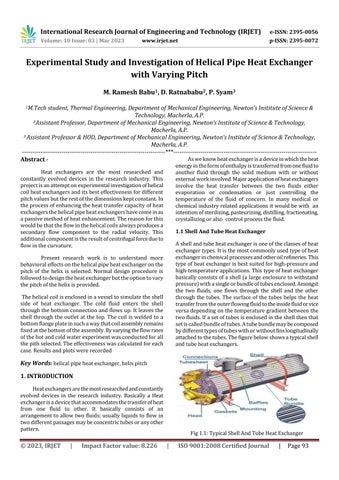
Ashellandtubeheatexchangerisoneoftheclassesofheat exchangertypes.Itisthemostcommonlyusedtypeofheat exchangerinchemicalprocessesandotheroilrefineries.This typeofheatexchangerisbestsuitedforhigh-pressureand high-temperatureapplications.Thistypeofheatexchanger basicallyconsistsofashell(alargeenclosuretowithstand pressure)withasingleorbundleoftubesenclosed.Amongst the two fluids, one flows through the shell and the other through the tubes. The surface of the tubes helps the heat transferfromtheouterflowingfluidtotheinsidefluidorvice versadependingonthetemperaturegradientbetweenthe twofluids.Ifasetoftubesisenclosedintheshellthenthat setiscalledbundleoftubes.Atubebundlemaybecomposed bydifferenttypesoftubeswithorwithoutfinslongitudinally attachedtothetubes.Thefigurebelowshowsatypicalshell andtubeheatexchangers.
1.2 Helical Pipe Heat Exchanger
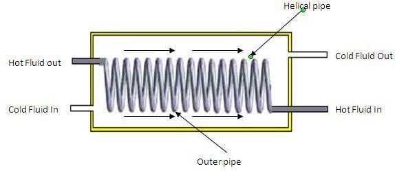
Inthistypeofheatexchangerthetubeisformedintothe helical pipe and placed inside the shell. This provides a secondaryflowtothefluidflowinginthispipe.Aschematic ofthehelicalpipeheatexchangerisshowninthefollowing figure.
Fig1.2:HelicalPipeHeatExchanger
Intheprocessofenhancingtheheattransfercapacityof heatexchangersthehelicalpipeheatexchangershavecome inasapassivemethodofheatenhancement.Thereasonfor this would be that the flow in the helical coils always producesasecondaryflowcomponenttotheradialvelocity. Thisadditionalcomponentistheresultofcentrifugalforce duetoflowinthecurvature.
Aslotofliteratureisavailabletoproveabouttheflowpattern thatisgeneratedinthehelicalandothercurvedchannels.It isalsoseenthatasymmetricalpairedvorticesusuallyaffects the main flow stream of thefluid. Also the details of these flowcharacteristicsarediscussedintheliteraturesurvey.
2. EXPERIMENTAL SETUP
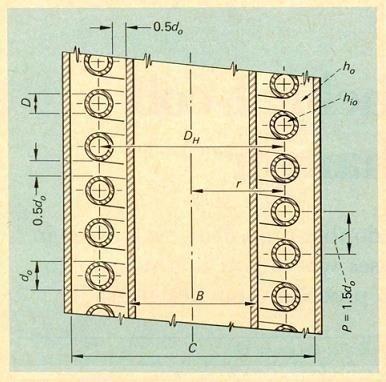
Thepipeusedtoconstructthehelicalsectionhas10mm inside diameter and 12.7mm outer diameter. The tube materialiscopper.ThePitchCircleDiameter(PCD)ofthecoil is80mmandtubepitchis20mm.Theremainingpartsofthe setuparemadeofmildsteel.Thehelicalcoilisenclosedina vesseltosimulatetheshellsideofheatexchanger.Thecold fluid enters the shell through the bottom connection and flowsup.Itleavestheshellthroughtheoutletatthetop.The coilisweldedtoabottomflangeplateinsuchawaythatcoil assembly remains fixed at the bottom of the assembly. A manuallycontrolledmechanismisprovidedtopushandpull thecoilaccordingtotheneed.
The helical coil test section is connected to a loop, which providesthenecessaryflowthroughthetubeandshellside ofthetestsectionandtherequiredinstrumentation.Atank with electric heater is provided to heat the water to be circulated through the helical coil with a total power of 2000W.Themanufacturedexperimentalsetupisasshownin thefollowingfigure.
Intheprocessofenhancingtheheattransfercapacityofa heatexchangersthehelicalpipeheatexchangershavecome inasapassivemethodofheatenhancement.Thereasonfor this would be that the flow in the helical coils always producesasecondaryflowcomponenttotheradialvelocity.
3. METHODOLOGY
3.1
Design Procedure
Thedesignwascalculatedasperthefollowingequations
1)ThecoiltubelengthLforNnumberofturns
2)Thevolumeutilizedbythecoil,Vc:
(π/4)d20L (2)
3)Annulusvolumeavailable,Va:
π/4)(C2–B2)��N (3)
4)Theavailablevolumeforthefluidtoflowintheannulus, Vf:
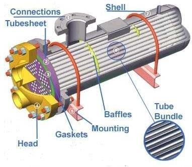
5)Equivalentdiameterofthecoiledtubeforshell-side, De:
����=4����/�������� (5)
3.2 Design Calculations
AssumedNumberofcoilsN=10
Radiusofthehelicalisr=80mm
Pitchofthehelicalisp=20mm
do=80+6.35=86.35mm
di=80-6.35=73.65mm
B=73.35–6.35=67.3mm
C=86.35+(1.5∗12.7)=105.4mm
Therefore:
��=10√(2��80)2+202=2016mm=2.016m
Vc=(π/4)86.352∗2016=1470m3
Va=(π/4)(105.42–67.32)20∗10=1.033m3
����=14.70−1.033=13.667m3
����=(4∗13.667∗106)/(π∗86.35∗2016)=99.96mm
4. RESULTS AND DISCUSSION
The experiment was conducted for different parameters.Theresultsaretabulatedasfollows.
Case 1: Full Length
4.1 Gap between Coils = 20 Mm, Parallel Flow & Full Length
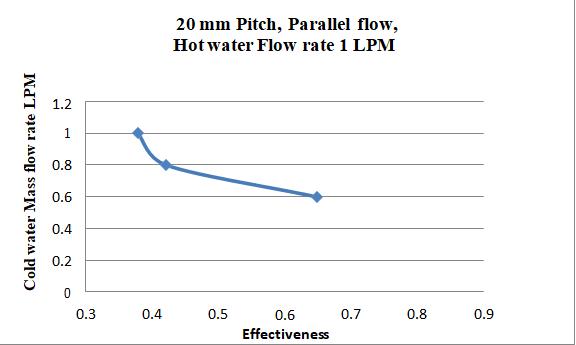
4.1.1ForConstantColdwaterflowas1LPM
Sample Calculation
Heat Flow capacity of cold water:
Cc=mcCpcwhereforwaterCpc=4.187kJ/kgK
mc=1LPM=(1000*10-6*1000)/60=0.0167kg/s
∴Cc=0.0167*4.187=69.91121kJ/K
Heat Flow capacity of Hot water:
Ch=mhCphwhereforwaterCph=4.187kJ/kgK
.mh=1LPM=(600*106*1000)/60=0.01kg/s
∴Ch=0.0167*4.187=41.87kJ/K
Fromtheabovewecanseethat:
Cmin=41.87kJ/KandCmax=69.91121kJ/K
Maximum Heat transfer theoretically:
Qmax=Cmin(th1–tc1)=41.87(69–38)=1297.753kJ /s
Heat Transfer in Cold water:
Qc=mc(tc2–tc1)=0.0167(43–38)=349.5978kJ/s
Heat Transfer in hot water:
Qh=mh
Average Heat transfer:
Q=(Qh+Qc)/2=(1608.15+359.5978)/2=978.8738
Effectiveness:
ε=(Q/Qavg)=978.8738/1297.753
ε=0.754284
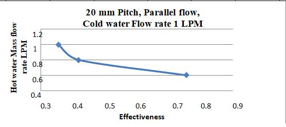
4.1.2 For Constant Hot water flow as 1 LPM
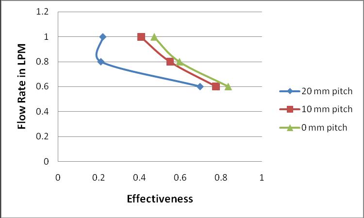
Fig4.3Plotforeffectiveness20mmGapbetweencoils, Counterflow,ColdwaterFlowrate1LPM
4.2.2 For Constant Hot water flow as 1 LPM
Fig4.2:Plotforeffectiveness20mmGapbetweencoils, Parallelflow,HotwaterFlowrate1LPM
4.2 Gap between Coils = 20 Mm, Counter Flow & Full Length
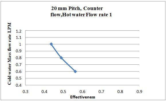
Fig4.4:Plotforeffectiveness20mmGapbetweencoils, Counterflow, HotwaterFlowrate1LPM
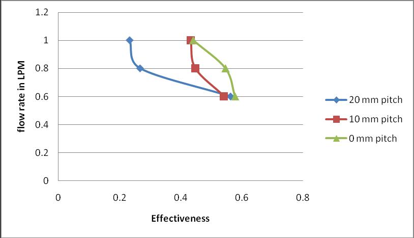
Similarlytheworkwascontinuedfor10mmpitchand0mm pitchforfulllengthpipewithsameflowconditionsincold andhotflowandtheresultsareshownbelow.
Table4.3:Temperaturesrecordedfor20mmgapbetween coils1LPMColdwaterconstantflow
4.2.1 For Constant Cold water flow as 1 LPM
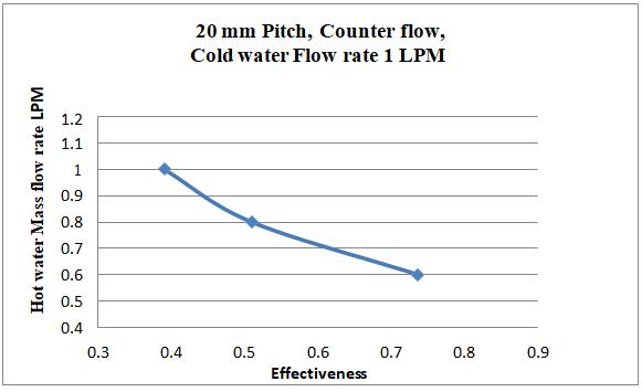
Table4.4:CalculatedEffectivenessfor20mmgapbetween coils1LPMColdwaterconstantflow
© 2023, IRJET | Impact Factor value: 8.226
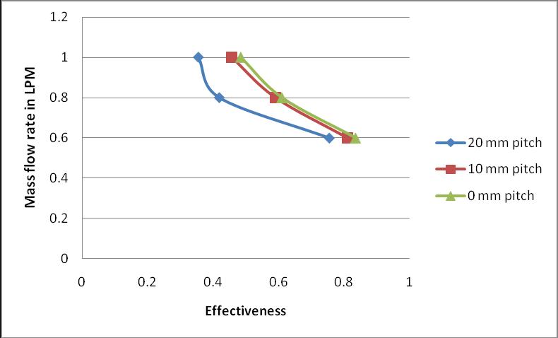
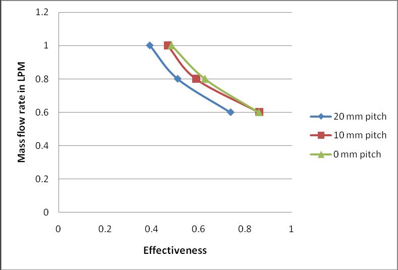
Fig4.5:PlotforeffectivenessVsMassflowrate consolidatedforparallelflow(coldwaterflowrate1LPM)
1LPM)
For half length:
1LPM)
Fig
foreffectivenessVsMassflowrate
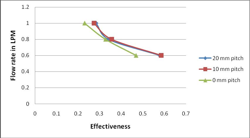
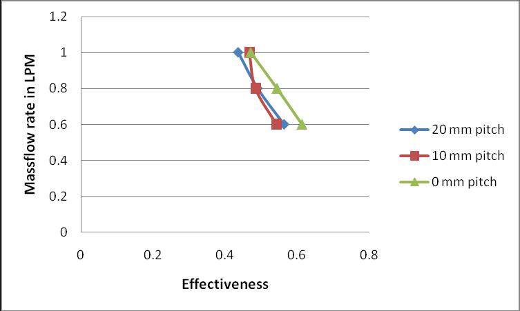
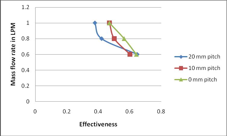
forparallelflow,forhalflength(coldwater flowrate1LPM)
5. CONCLUSIONS
Theheatexchangerwasdesignedfirstaccordingtothe normal design procedure. The heat exchanger was manufacturedasthedimensionsobtainedfromthedesign. Thesamewasrepeatedforthedifferentflowratesofthecold water,keepingthehotwaterflowrateconstant.Effectiveness wascalculatedforalltheflowrates.Theworkwasdonefor
pitch of 20 mm,10 mm,0 mm in full lengthand halflength conditions.
Weobservethattheeffectivenessingeneralreduceswiththe increaseofthemassflowrateirrespectiveofthepitch.
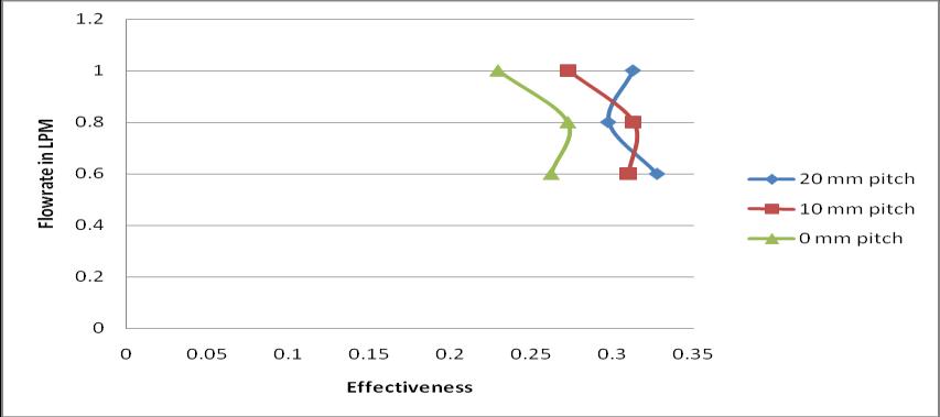
Fromtheresearchitcanbeeasilyconcludefromtheresults thatwhenthegapbetweenthecoilswas10mmand0mm theeffectivenesswasconsistentforbothparallelandcounter flow arrangements, in both half length and full length readings.
The consolidated graphs plotted also reveal for the half length readings that the length chosen according to the designi.e.2misaccurateandthelengthofthecopperpipe cannotbereducedfurther.
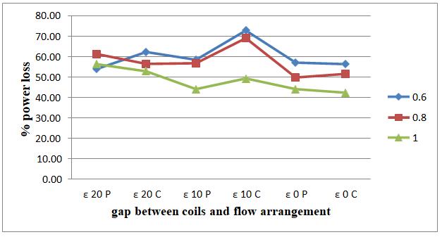
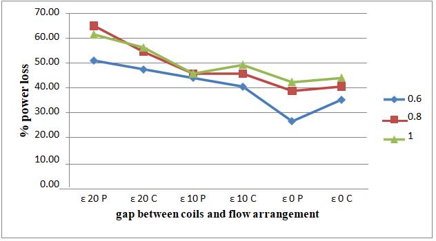
Itisbeenobservedthatwhenpowerlosseswerecalculated and plotted accordingly, the maximum power loss has occurredwhentheflowrateofcoldfluidwas0.6kg/sat10 mm gap between the coils for counter flow. And the value was 72.76%. It is also observed that the minimum power losses are occurred at when the hot fluid flow rate was maintainedat0.6kg/swhentherewasnogapbetweenthe coils for parallel flow arrangement. And the value was 25.58%.
REFERENCES
[1] “Numericalandexperimentalstudiesofadoublepipe helical heat exchanger” by Timothy j. Rennie department of bioresource engineering, mcgill university, montreal, submitted august 2004, a thesis submitted to mcgilluniversityinpartialfulfillmentoftherequirementsof thedegreeofdoctorofphilosophy.
[2] “Helically Coiled Heat Exchangers - Basic design Applications” by J. S. Jayakumar Professor, Dept. of Mechanical Engineering, Amrita Vishwa Vidyapeetham, AmritaSchoolofEngineering,Amritapuri,Kollam,India.
[3] “FabricationandAnalysisofTube-In-TubeHelical Coil Heat Exchanger” by Mrunal P.Kshirsagar, Trupti J. Kansara, Swapnil M. Aher, International Journal of EngineeringResearchandGeneralScienceVolume2,Issue3, April-May2014ISSN2091-2730.
[4] “ Thermal Analysis of a Helical Coil Heat Exchanger”by Amol Andhare, V M Kriplani, J P Modak, International Journal of Innovative Research in Advanced Engineering(IJIRAE)ISSN:2349-2163
[5] “Thermal Analysis Validation for Different Design TubesinaHeatExchanger”byRoshan.V.MarodeandAshok. J.Keche,InternationalJournalofEngineeringResearchand GeneralScienceVolume3,Issue1,January-February,2015, ISSN2091-2730.