Review of Battery Management Systems (BMS)
Nikita Shelke1 , Chaitali Nilawar2 , Gajajnan Udas3Abstract - The most crucial component of any electric vehicle (EV) is its battery storage, which stores the energy needed for the vehicle to function. So, an effective battery management system is required in order to get the most out of a battery while also ensuring its safe operation. BMS is a crucial component of any electric car, so there is still a lot of research going on to improve battery management systems.
Monitoring, regulating, andoptimizingtheperformanceof the battery modules in an electric vehicle is very important. Another is the ability to regulate how the components are disconnected from the system in case of irregular conditions. This management system is nothing but the “battery management system (BMS)”. BMS keeps track of the parameters, calculates SOC, and offers essential services to assure the battery's safe functioning. Thefunctionalityof BMS, topologies of BMS, and future technologies like wireless BMS are all thoroughly reviewed in this paper.
Key Words: EV (Electric Vehicle), BMS (Battery ManagementSystem),SOC(StateofCharge),SOH(Stateof Health),WBMS(WirelessBMS)
1. INTRODUCTION
Research indicates that automobiles with internal combustionenginesareresponsibleforproducing18%of the suspended particles, 27% of the volatile organic substances,28%ofPb,32%ofnitrogenoxides,and62%of the CO of airborne pollution in America [7]. Moreover, traditionalcarsareresponsiblefor25%ofallatmospheric CO2thatisrelatedtoenergyandisthemaincontributorto thegreenhouseeffect[7].Thenumberofpeopleusingboth public and private transportation is growing, which contributes to daily increases in air pollution. As a result, electriccarsaregettingmorepopular.
Thefollowingessentialpartsareoftenfoundinanelectric car:anelectricmotor,MCU, traction battery,BMS,plug-in charger that can be used independently from the vehicle, wiring harness, regenerative braking system, vehicle bodyand frame. When utilizing lithium-ion batteries, the battery management system is one of the most important parts
Thesystembatterypack'soperationalsafetyisverifiedby the BMS model. A BMS's main purpose is to protect the
battery. Monitoring each cell is essential due to ageing problems, cell balancing concerns, and safety concerns. Moreover,BMSmakessurethatanyabnormalstateinthe system is addressed by the predetermined corrective procedures. The BMS controls the system temperature because a rise in temperature may affect the power consumptionprofileofthesystem[1].
TheBMSshouldnotifytheuserandcarryoutacorrective operation wheneveranyabnormal circumstances,such as overvoltageoroverheating,aredetected[5].TheBMStook actions based on the factors such as battery charging and discharging rates, cell voltage, temperature, current, estimatedstateofchargeandstateofhealth,etc[7].
2 FUNCTIONS OF THE BMS
BMStakescareofthefollowingthings[8]:
Batterycharginganddischargingrates
Taking prevention in accordance with the cell voltage,temperature,andcurrent.

Estimatingthestateofchargeandstateofhealth
CellBalancing
Aspecificcellorgroupofcellsknownasamoduleisusedfor thecontinuousmonitoringofthecompletebatterypack.The preferredchoiceforbatterypacksinavarietyofconsumer items is lithium-ion rechargeable cells due to their high energydensity[8].
Indeed, while they work incredibly well, they can be relativelydurableifusedinsideasafeoperatingarea(SOA). If the battery performs outside of the SOA, it will suffer performancedamageandpotentiallydangerousissues.
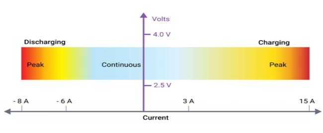
2.1 Current Protection:
Monitoringthecurrentandvoltagesinthebatterysystemis partoftheelectricalprotectionstrategy.TheelectricalSOA ofeverybatterycellisrestrictedbyitscurrentandvoltage. As shown in Figure 1, BMS will safeguard the pack by limitingoperationoutsidethespecifiedcellratings.Inorder to promote longer battery life, more de-rating may frequentlybeusedtostaywithintheSOAsafezone.
ABMS that offers current protection will use a maximum continuouscurrent.But,thiscouldcomebeforetoaccount for a sudden change in the load conditions, such as the suddenaccelerationofanelectricvehicle.Bycombiningthe currentandmakingadecisiontoeitherreducetheavailable currentorstopthepackcurrentaltogetherafterdeltatime,a BMScanincorporatepeakcurrentmonitoring.Thisenables theBMStobetolerantofhighpeakdemandsaslongasthey are not excessive for an extended period of time, while simultaneouslyhavingvirtuallyinstantaneoussensitivityto extremecurrentpeaks,suchasashort-circuitconditionthat hasnotbeendetectedbyanyresidentfuses.
With heating and cooling, BMS may regulate the battery pack'stemperature.
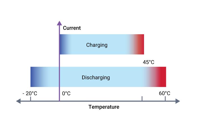
2.2 Voltage Protection:
A lithium-ion cell must function within a specific voltage range,asshowninFigure2.Theintrinsicchemistryofthe chosenlithium-ioncellandthetemperatureofthecellsat anygiventimewilleventuallydecidetheseSOAbounds.
The BMS must be aware of these boundaries since it will issueordersbasedonhowcloseasituationistotheselimits. For instance, a BMS may ask that the charging current be reducedgraduallyasthehighvoltagelimitisapproached,or itmayaskthatitbestoppedentirelyifthelimitisachieved. Toavoidcontrolchatterregardingtheshutdownthreshold, this restriction is typically complemented by additional intrinsicvoltagehysteresisconsiderations.
Naturally,theBMSmustprioritizethedriver'ssafetyabove all else while safeguarding the battery pack to avoid irreparableharm.
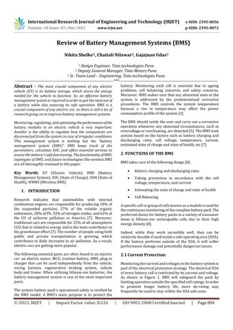
2.3 Temperature Protection:
Althoughlithium-ioncellsfirstappeartooperateinawide rangeoftemperatures,theiroverallbatterycapacityactually decreases at low temperatures because chemical reaction ratesaremarkedlysloweddown.
Duringsub-freezingcharging,theanodemayexperiencethe metalliclithiumplatingphenomenon.Thecells'capacityis reducedasaresultofthispermanentdamage,andtheyare alsomoreinclinedtofailunderdifficultcircumstancessuch asvibration.
2:TemperatureProtection
2.4 State-of-Charge Estimation:
The BMS's ability to monitor the battery's state of charge (SOC)isoneofitsfeatures.Theusercouldbealertedandthe charginganddischargingprocesscouldbemanagedbythe SOC. There are three ways to calculate SOC: direct measurement, coulomb counting, and combining the two methods[6].
It is easy to determine the SOC directly with a voltmeter becausethebatteryvoltagedeclinesalmostlinearlyoverthe discharging cycle of the battery. The relative value of a battery's charge is calculated using the coulomb-counting methodbyintegratingthecurrentflowingintooroutofthe battery.
Forthecombiningmethod,whentheactualchargeisgetting closetoeitherend,calibratetheSOCandavoltmetercanbe used to monitor the battery voltage. In the meantime, the relative charge flowing through the battery might be calculatedbyintegratingthebatterycurrent.
2.5 State-of-Health Estimation:
Incontrasttootherbatteries,thestateofhealth(SOH)isa measurement that assesses a battery's general health and abilitytoprovidethenecessaryperformance.TheSOHofthe cellcanbedeterminedusingtheimpedanceorconductance ofthecell,bothofwhichchangeconsiderablywithageing.In actuality, the SOH could be determined by taking just one readingoftheresistanceorconductanceofthecell.
2.6 Cell Balancing:
Cell balancing is a technique used to compensate for weakenedcellsbybalancingthechargeonallofthecellsto increase battery life. Weak cells may undergo excessive
stress while being charged, weakening further until they ultimatelyfail,leadingtoanearlybatteryfailure.TheBMS mayuseoneofthethreecellbalancingstrategiesbalancing, passive balancing, or the charge shunting method to equalizethecellsandpreventindividualcellsfromgetting overstressedwhiletakingintoconsiderationthelifecycleof thecells.Duringactivecellbalancing,chargeistransferred from the healthier cells to the weaker cells. Dissipative methodsareusedinpassivebalancingtoidentifythepack's highest-charged cells, which are signaled by higher cell voltages.Oncethevoltageorchargeisequaltothevoltage ontheweakenedcells,theextraenergyisthendischarged throughabypassresistor.
First,thevoltageofthecellinchargeofshuntingwouldbe raisedtoitsratedvoltage.Thecurrentwillstopchargingthe fully charged cells as soon as the cell reaches its rated voltage and continue charging the weaker cells until they reachtheirratedvoltage.
3. BMS TOPOLOGY
Three basic topologies are used in the design of BMS hardware.
3.1 Distributed Topology:
Inadistributedtopology,eachcellisequippedwithavoltage meter,adischargebalancer,andadigitalcommunications devicethatcanshutoffthechargerandreportonitsstate.
Thisconstructionhasthebenefitsofbeingstraightforward and highly reliable. The drawbacks include the need for a largenumberofprintedcircuitboardsformini-slavesand the challenge of mounting the boards on specific kinds of cells.
This topology doesn't need complicated inter-vehicle communications and only calls for one installation site. However, since the controller is the only source for cell balancing,toomuchheatmightbeproduced.Additionally, the cells are dispersed throughout the car, necessitating wiringtoacentrallocation.
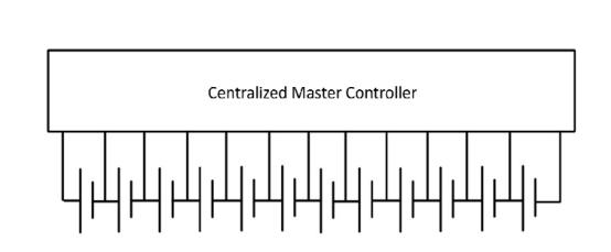
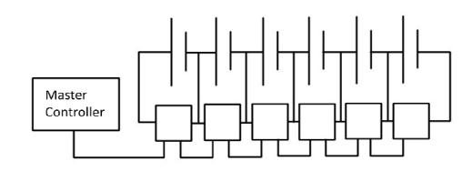
3.2 Centralized Topology:
Incentralizedtopology,eachbatterypackcellisimmediately connectedtoacentralizedmastercontrolunit.Allcellsare safeguardedandbalancedbythemanagementunit,which alsoservesanumberofotherpurposes.
3.3
Modular Topology:
Toconsolidatethedatatoamastercontrollerinthemodular framework,severalslavecontrollersareused.
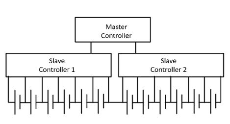
Theseparatecellscanbeconnectedwithoutprintedcircuit boards. However, when this structure is used in electric vehicles,itischallengingtoaccomplishisolatedmaster-slave communications
Modulartopologycanbedesignedusingthreeinterfaces:
3.3.1CANInterface
3.3.2SPIInterface
3.3.3WirelessBMS
3.3.1 CAN Interface:
The CAN interface is used to establish communication betweenthemasterandslave.
Given CAN bus' success in automotive uses, it offers a practicednetworkforconnectingbatterymodulesbutneeds
anumberofextraparts.Thecommunicationisestablished usingtheSPIinterface.
The installation of an isolated CAN network via an SPI interfacerequiresaCANtransceiver,amicroprocessor,and anisolator.
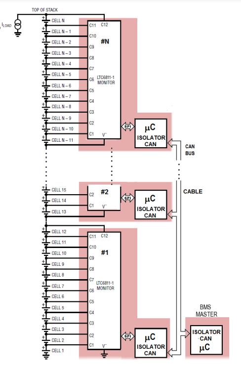
ThemaindrawbackofaCANbusistheextraexpenseand boardsneededfortheseextracomponents.
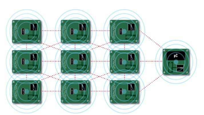
3.3.3 Wireless BMS:
InsteadofusingCAN Bus cablesorisoSPItwistedpairsto linkthemodules,awirelessconnectionisusedinawireless BMS.
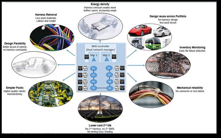
The conventional wired connections between the battery packsandthebatterymanagementsystemarereplacedin this wireless BMS prototype vehicle by a master board controller and a wireless network manager. All communicationbetweenthehostcontrollerandthenetwork manager will be carried out via isoSPI. Following that, a wirelessconnectionbetweenthenetworkcontrollerandthe slaveboardswillbeestablished.Wirelesscontactbetween thenetworkmanagerandslaveboardscanbeestablished usinganRFantenna.
The wireless network manager allows for the flexible placementofbatterymodulesandmakesitpossibletoput sensors in places where a wiring harness was previously unsuitable.
SensorslikeSmartMeshcanprovidetheBMSMasterwith additionalinformationlikecurrentandtemperatureforuse inbatterystateofcharge(SOC)computations.Withtheuse of these sensors, readings at each node will be properly timestamped and each node will be automatically timesynchronizedwithinacoupleofμs.
3.3.2 SPI Interface:
2-wireisoSPIcanbeusedinsteadofCANBusinterface.The CAN system requires four wires, whereas the isoSPI interfaceonlyneedsasingletwistedpairandatransformer.
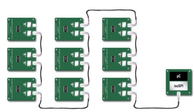
The isoSPI interface offers a high RF noise immunity interface that enables daisy-chaining of modules over lengthycablelengthsanddataratesofupto1Mbps.
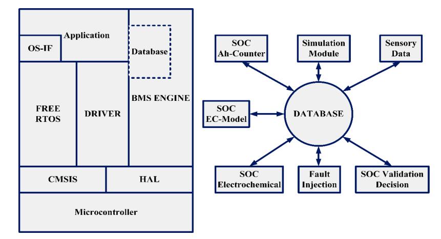
4. 1 Software Architecture of Wireless BMS:
Differenttaskscanbecompletedconcurrentlyandwithout interruptioninthesoftwarearchitecture.Theinitialduties ofaBMSsoftwarearchitect,includingvoltageandcurrent measurement, overcurrent and voltage protection, temperature monitoring, and protective relay actuation, must be completed right away to guarantee BMS safety. Threelayersmakeupmostsoftwaredevelopment:theHAL layer, the base software, and the application software.
Thelinkbetweentheoperatingsystem'shigherlayersand theunderlyinghardwareisprovidedbyHAL.
Basesoftwareincludesadriverdevelopmentframeworkfor microcontrollers. MATLABisusedtoimplementallofthe BMSfunctionality-relatedstrategiesintheapplicationlayer.
4.2
Benefits of Wireless BMS:
•Wirelessbattery-managementsystems(WBMS)havethe potentialtofurtherincreasethesafetyanddependabilityof theentirebatterysystembycontinuallymonitoringbattery packsforthestateofhealth(SOH)andstateofcharge(SOC). Byswitchingtoawirelessbattery-managementsystem,the car'sdrivingrangecanbeincreasedwhilemaintainingthe samelevel ofenergy efficiencydue tothesystem'slighter weight.
•Inaddition,acommoncauseofcablefailuresisthewire harness and connectors. Because they do not require physicalharnessesorwires,wirelessBMSshouldresultin lowerend-userrepaircosts.Byallowingthereplacementof abatterymoduleratherthantheentirebattery'sinternals, maintenanceisalsomadesimpler.
Conclusion:
Theprimaryobjectiveofthispaperistoperformathorough reviewofbatterymanagementsystems.
In this paper, we addressed the various BMS functions, includingcellbalancing,SOC,SOHestimation,temperature protection, voltage protection, current protection, and temperatureprotection.
ThedifferentBMStopologiesandcommunicationinterfaces, suchasSPI,CAN,andwirelessBMS,werealsomentioned.
ExpandedBMScapabilityismadepossiblebywirelessBMS.
REFERENCES
[1]HossamA.Gabbar,AhmedM.OthmanandMuhammadR. Abdussami(11April2021). “ReviewofBatteryManagement Systems (BMS) Development and Industrial Standards” Technologies. Retrieved from https://doi.org/10.3390/ technologies9020028
[2] A. Hariprasad, Priyanka, R. Sandeep, V. Ravi and O Shekar,Vol.9Issue(05,May-2020).“BatteryManagement System in Electric Vehicles” International Journal of Engineering Research & Technology (IJERT). DOI: 22780181.
[3]AnanthrajCRandArnabGhosh(30July2021).“Battery Management System in Electric Vehicle”. IEEE. DOI: 10.1109/ICNTE51185.2021.9487762
[4] Rakshitha Ravi and Usha Surendra (January 2021). “Battery Management Systems (BMS) for EV: Electric VehiclesandtheFutureofEnergy-EfficientTransportation” DOI:10.4018/978-1-7998-7626-7.ch001
[5]AkashNandargiandRohitJirole(06June2020).“Battery Management Systems in Electric vehicle”. International JournalofEngineeringResearch&Technology(IJERT).DOI: e-ISSN:2395-0056
[6]RuiHu(2011).“BatteryManagementSystem ForElectric VehicleApplications”.AThesisSubmittedtotheFacultyof Graduate Studies. Retrieved from: Battery Management SystemForElectricVehicleApplications(core.ac.uk)
[7]A.Hariprasad,I.Priyanka,R.Sandeep,V.Ravi,O.Shekar (23-05-2020).“Battery Management System in Electric Vehicles” .InternationalJournalofEngineeringResearch& Technology(IJERT).DOI:ISSN:2278-0181
[8] Synopsys “What is a Battery Management System?” Retrieved from: What is a Battery Management System (BMS)?–HowitWorks|Synopsys
[9]AkashSamantaandSheldonS.Williamson(September 2021).“ASurveyofWirelessBatteryManagementSystem: Topology,EmergingTrends,andChallenges”.ResearchGate. DOI:10.3390/electronics10182193
[10]GregZimmer.“WirelessBatteryManagementSystems Highlight Industry’s Drive for Higher Reliability”. Linear Technology. Retrievedfrom:MicrosoftWord-S65-Wireless BMSEN.docx(analog.com)