IoT Based Electric Vehicle Charging System
Rutuja RajoleAbstract –
Electric vehicles are a new and forthcoming technology in the transportation and power sector that have numerous benefits in terms of profitable and environmental. This study presents a comprehensive review and evaluation of different types of electric vehicles and its associated outfit in particular battery bowl and charging station. A comparison is made on the marketable and prototype electric vehicles in terms of electric range, battery size, bowl power and charging time. The different types of charging stations and norms used for charging electric vehicles have been outlined and the impact of electric vehicle charging on mileage distribution systems is bandied. The methodology presented then was time- and cost-effective, as well as scalable to other associations that enjoy charging stations. Electric vehicles (EVs) are getting decreasingly popular in numerous countries of the world. EVs are proving further energy effective and environmental friendly. However, the lack of charging stations restricts the wide relinquishment of EVs in the world. As EV operation grows, further public spaces are installing EV charging stations.
Key Words: ATMEGA8, RFID, Proximity Sensor, ESP8266, Touch Screen.
1. INTRODUCTION
1.1 Necessity
Since the early 2000, India’s crude oil painting significanceshaverisenexponentially.Thedemandfor oil painting grew by5.1 in 2016, advanced than the world’s largest net importers, the US(0.7) and China(2.9), making India the world’s third largest crude oil painting consumer.Indiaranksasthethirdlargestcarbonemitting country in the world counting for 6 of the global carbon dioxide emigrations from energy combustion. According to the WHO Global Air Pollution Database (2018), 14 out ofthe20mostweakenedmetropolisesoftheworldarein India4. Rising population – a sustainable mobility challenge India’s current population of1.2 billion is anticipatedtoreach1.5billionby2030.Indiaistheworld’s fourth largest patron of internal combustion machine (ICE) grounded motorcars. The growth in the automotive request in India has been the loftiest in the world,
growing at a rate of 9.5 in 2017. An adding uptake in electric vehicles is likely to pose a challenge to the being automotive request if the country does not plan its transitiontowardsnewermobilityresultsanddevelopthe needed manufacturing capabilities. Electric Mobility an implicitresultforIndia.
1.2 Need
In 2017, Indian government pushed a major policy of dealingatleast6-7millionEV’sinIndiaby2020.Theyare planning to vend only EV’s by 2030. However, numerous experts in machine assiduity blamed this plan and said thatitmightbefail.Onlyreasontheyhavestated,islackof structure, and majorly lack of ‘Charging stations ’. Indian government is really trying to push electric vehicle in our ecosystem.However,peoplearereticenttobuyanelectric vehicle. Reason people are not buying electric vehicle is ‘RangeAnxiety’.Rangeanxietyissolicitudeonthepartof a person driving an electric vehicle that the battery will run out of power before the destination or a suitable charging point is reached. So what is the point in buying EV? Why would I, you will buy an electric vehicle? Then, chargingstationplaysvitalpart
1.3 Motivation
Electricvehiclesarea new andforthcomingtechnology in the transportation and power sector that have numerous benefitsintermsofprofitableandenvironmental.Electric vehicles (EVs) are getting increasingly popular in numerous countries of the world. EVsare proving further energyeffectiveandenvironmentalfriendly.However,the lackofchargingstationsrestrictsthewiderelinquishment ofEVsin the world.Thishasmotivateddesign eachalong sothatitisstonerfriendlysystem.
1.4 Objective
i. To design IoT based electric vehicle charging system.

ii. Todesignuserfriendlyandreliablesystem.
iii. Toprovidefastchargingtoelectricvehicle.
2. Analysis & Design Approach
2.1 Block Diagram:
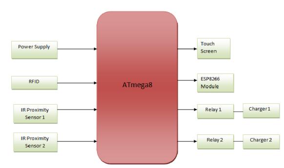
2.2 Block Diagram Description:
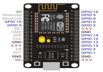
HereweusedATmega8controllerforthisproject.
Power Supply, which is the first block, decided to be the dual power supply of 12v, 5v. The 5v supplyisforcontrollerandthe12visrequiredfor therelays.
The RFID is used for the identification of the users.WewillprovideRFIDcardtotheusers.
The IR Proximity Sensors are used to check the availability of charging slots. If the place is available,thenmessagewillbedisplayedontouch screendisplay.
TheEsp8266moduleisusedtosendmessagesto theuserandforcollectingdata andanalyzingthe data.
The various messages are displayed to the user aboutchargingstatus,amount,andtimeonTouch screen.
2.4 Component Used
2.4.1 ATMEGA8
It's an 8-bit CMOS technology grounded microcontroller belongingtotheAVRfamilyofmicrocontrollersdeveloped in 1996. It is erected on RISC (Reduced Instruction Set Computer)armature.ATmega8microcontrollerconsistsof 1KBofSRAM,8KBofflashmemory,512bytesofEEPROM, 23generalpurposeI/Olines,32general-purposeworking registers, three flexible timekeeper/ Counters, internal and external interrupts, a periodical programmable USART. The device operates between2.7-5.5 volts. By executing important instructions in a single timepiece cycle, the device achieves throughputs approaching one MIPS per MHz, balancing power consumption and processingspeed.
2.4.2 Power Supply
Power Supply Units (PSU) do not supply systems with power- rather they convert it. Specifically, a power force converts the interspersing high voltage current (AC) into directcurrent(DC),andtheyregulatetheDCaffairvoltage tothefineforbearanceneededforultramoderncomputing factors. Then we used binary power force of 12V and 5V, inwhich12Vgoestorelayand5Visforregulator.
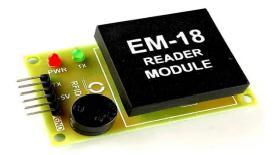
2.4.3 RFID
RadioFrequencyIdentificationisatypeofcommunication betweenatransmitter(transponderortag)andareceiver (reader).Thesystemworksfullyautomaticallyandisused for contactless communication, identification and localization of objects such as goods, medicines, vehicles orlivingbeings.
EM-18FeaturesandSpecifications
OperatingvoltageofEM-18:+4.5Vto+5.5V
Currentconsumption:50mA
CanoperateonLOWpower
Operatingtemperature:0ºCto+80ºC
Operatingfrequency:125KHz
Communicationparameter:9600bps
Readingdistance:10cm,dependingonTAG
IntegratedAntenna
ProximitySensorsareusedtodetectobjectsandobstacles in front of the sensor. Sensor keeps transmitting infrared lightandwhenanyobjectcomesnear,thesensordetectsit bymonitoringthereflectedlightfromtheobject.
FeaturesofIRProximitySensor:
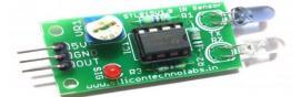
IRtransmitter
AmbientlightprotectedIRreceiver
3pineasyinterfaceconnectors
IndicatorLED&PowerLED
Distance2cmto30cm
Candifferentiatebetweendarkandlightcolors
ActiveLowonobjectdetection
3.3to5Voperation
The ESP8266 Wi-Fi Module is a self-contained SOC with integrated TCP/IP protocol stack that can give any microcontroller access to your Wi-Fi network. The ESP8266 is capable of either hosting an application or offloading all Wi-Fi networking functions from another applicationprocessor.
FeaturesofESP8266:
802.11b/g/n•Wi-FiDirect(P2P),soft-AP
IntegratedTCP/IPprotocolstack
IntegratedTRswitch,balun,LNA,poweramplifier andmatchingnetwork
Integrated PLLs, regulators, DCXO and power managementunits
+19.5dBmoutputpowerin802.11bmode
Powerdownleakagecurrentof<2ms
Standbypowerconsumptionof<1.0mW(DTIM3)
4MBFlashMemory
Integratedlowpower32-bitCPUcouldbeusedas applicationprocessor
SDIO1.1/2.0, SPI,UART• STBC,1×1 MIMO,2×1 MIMO
A-MPDU & A-MSDU aggregation & 0.4ms guard interval
Wakeupandtransmitpacketsin<2ms
Standbypowerconsumptionof<1.0mW(DTIM3)
2.4.6 Relays
Relays are electric switches that use electromagnetism to convertsmallelectricalstimuliintolargercurrents.These conversions occur when electrical inputs activate electromagnets to either form or break existing circuits.
FeaturesofRelay:
MaxCurrent:5AAC/DC(max).
MaxVoltage:250VAC/30VDC.
NominalVoltage:12V.
Coilresistance:270Ω.
CoilCurrent:44.4Ma.
OperatingVoltage:8.6to21.6V
2.4.7 Touch Screen
Thetouchscreenenablestheusertointeractdirectlywith whatisdisplayed,ratherthanusingamouse,touchpad,or other such devices (other than a stylus, which is optional formostmoderntouchscreens).
FeaturesofTouchScreen:
320x240Resolution
RGB65Ktruetolifecolors
TFTscreenwithintegratedresistivetouchpanel
4pinTTLserialinterface
4M Flash memory for User Application Code and Data
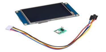
On board micro-SD card slot for firmware upgradation
VisualArea:57.6mm(L)×43.2mm(W)
Adjustable Brightness: 0~180 nit, the interval of adjustmentis1%•5V65mApowerconsumption
Compatible with Raspberry Pi A+, B+, Pi 2, Pi 3, Arduino.
3. Hardware Design
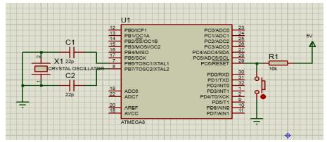
3.1 Circuit Design
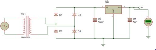
3.1.1 Power Supply
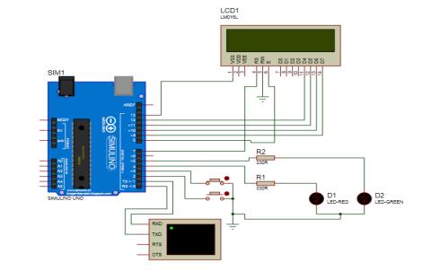
3.1.2 Main Circuit Diagram
Fig
3.2 Calculation
CircuitDiagramofsystem
Power supply Calculations:
Voltage Rating:
AswerequireVldcofalmost8Vsobyconsidering the voltage drop across diodes and other components.Wedecidedtouse12Vtransformer.
As,Vrms=Vm/√2
∴Vm=Vrms*√2
∴Vm=16.97V
As,Vldc=2Vm/π
∴Vldc=10.80V
Byconsideringthediodedropofaround1.4Vwe get,
Vldc = 9.54V
This is more than sufficient for IC 7805 for generatingoutputof+5V.
CurrentRatingAswerequireIldcofalmost1Aso we decided to use 1A transformer current rating. Ifwechoose 1Athen weget0.9AasIldcwhichis notsufficient.
As,Irms=Im/√2
∴Im=Irms*√2
∴Im=2.82A
As,Ildc=2Im/π
∴
Ildc = 1.79A
CapacitorCalculations:
If we assume that our step down transformer reduces the amplitude of 50 Hz sine wave from 230Vto12V.
Thedischargetimeofthecapacitorin thiscaseis Tdischarge=1/(2*f)
As,f=50Hz
∴Tdischarge=10ms
Now, at the beginning of each discharge period our capacitor is charged up to the peak value i.e. Vmax=16.97V.
In order to prevent our capacitor voltage going below Vmin= 7V in the end of the discharge period, so the capacitor value should be chosen withtheequation:
C=(Imax*Tdischarge)/(Vmax-Vmin)
∴C=(1A*10ms)/(16.97-7)
C = 1mF
4. Implementation, Test & Performance
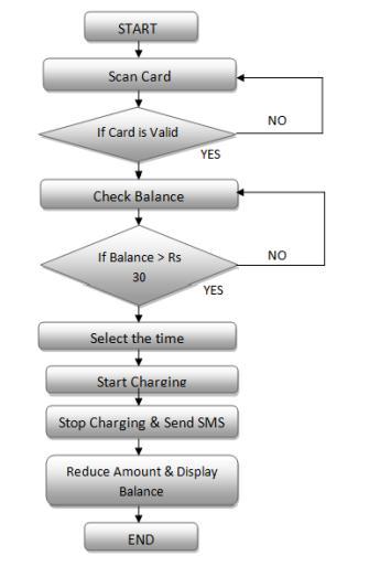
4.1 Flow Chart
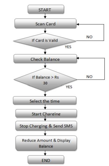
Flowchartdescription:
1. Firstly,customerarrivesatthechargingstationto chargethecar.
2. Then he will wait for swiping the card, after swiping the card, the system will check the space forthearrivedperson.
3. Also, check for availability of either one or two spaces.
4. If space is vacant, the message is shown on the screen that space is vacant; you can charge your vehicle.
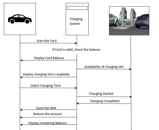
5. Then the customer will proceed for the next process.
6. Hewillswipethecard.
7. After swiping, a balance checking process will be goingoninthesystem.
8. Ifthereisbalanceinthecard,thenthesystemwill allow that person, but if there is no sufficient balance, the system will give the message for repeating the process until the available balance is sufficient and display the message to recharge yourcard.
9. After the balance is checked, the customer has to selectthetimingforcharginghisvehicle.
6. FUTURE SCOPE
In future, we are planning to include some interesting features like solar-based system and battery voltage detectors to check the status of battery of vehicle. We are planning to link the RFID cards with user’s prepaid bank account using various payment apps like paytm, google pay.Theseextrafeaturesmakethesystemmoreaccurate, reliableanduserfriendly.
REFERENCES
[1] Electric Vehicles Charging Technology Review and OptimalSizeEstimation,Published:02October2020
[2] Smart Science volume 6 (2018), issue 1, A Comprehensive Review on Solar Powered Electric Vehicle Charging System by Saadullah khan, Aqueel Ahmad, FurkanAhamd,MahdiShafaatiShemami,Mohammadsaad Alam & Siddiq Khateeb , deparment of electrical engineering,Aligarah,India.
[3] Engineering Science and Technology, an International Journal 21 (2018). Review of static and dynamic wireless electricvehiclechargingsystembyChiragPanchal,Sascha Stegen, Junwei Lu Griffith School of Engineering, Griffith University,NathanCampus,Brisbane4111,Australia.
[4] Trivedi, N., Gujar, N. S., Sarkar, S., & Pundir, S. P. S. (2018).Differentfastchargingmethodsandtopologiesfor EV charging. 2018 IEEMA Engineer Infinite Conference (eTechNxT).doi:10.1109/etechnxt.2018.8385313
10. Chargingwillstart.
11. After charging is finished, the system will display thatmessagethatyouarechargingisdone.
12. Then the amount is reduced from the customer’s account. In addition, final balance will be displayedonscreen.
5. CONCLUSIONS
The purpose of this project is to provide fast charging to electric vehicle. In the proposed EV charging System, introduction of mobile application will facilitate connectivity user's interaction. The Simulation tool helps onthischargingprocesstosimulatebehavioranoperating condition under different assumptions. The application of IoT approaches has a great potential, once we are able to store consumption and production data and the knowledge information created which can help both consumers and producers. Mobile devices and applicationswillhelpontheaccesstoinformation.
[5] Chynoweth, J., Ching-Yen Chung, Qiu, C., Chu, P., & Gadh, R. (2014). Smart electric vehicle charging infrastructure overview. ISGT 2014. doi:10.1109/isgt.2014.6816440
[6]Dharmakeerthi,C.H.,Mithulananthan,N.,&Saha,T.K. (2013). Planning of electric vehicle charging infrastructure.2013IEEEPower&EnergySocietyGeneral Meeting.doi:10.1109/pesmg.2013.6672085
[7]Links
https://en.wikipedia.org/wiki/Charging_station
https://bit.ly/2NAmQRv
https://whatis.techtarget.com/definition/electric -vehicle-charging-station
https://www.slideshare.net/mobile/SarangBongi rwar/charging-stations-for-electric-vehicle