Designing shear walls based G+5 Commercial building
Dheekshith K1 , Reshmi Raghunath21Assistant Professor, Dept. of Civil Engineering, Srinivas University Institute of Engineering and Technology, Karnataka, India

2M.Tech student, Dept. of Civil Engineering, Srinivas University Institute of Engineering and Technology, Karnataka, India ***
Abstract - Even though concrete structures make up a sizable component of civil infrastructure, due to the vast material discreteness their reliability is generally low. Inlight of this, civil engineering pays constant attention to the safety of concrete structures. It is crucial to assess the state of concrete structures as a result by following simple safety measures. Among all natural disasters, seismic activity are thought to be the most unpredictable. To reduce the seismic impact consider this when analysing and designing any structure. Today’s designers and engineers are paying more attention to earthquake resilience. When analyzing and planning any construction, keeping this in mind to lessen the seismic impact. So as a result in high- rise building facing lateral wind as well as seismic forces, shear walls used. In this project, designeda shear wallbasedG+5commercialbuilding. Shear wall construction often have a regular layout and elevation. This project utilizes ETABS for building modeling and analysis.
Key Words: Shear walls, Seismic design, ETABS, Commercial building, Storey drift.
1.INTRODUCTION
Civil engineering construction activity have increased dramatically during the past few years. Inorder for our society to function properly, complex systems like dams, buildingsandbridgesmustbebuilt.Theyexperienceheavy loading and its possible that this will cause performance changes over time. For society to be prosperous economically and industrially civil buildings safety and durabilityarecrucial.Unfortunately,alargenumberofour aging civic structures are degrading due to persistant extreme climatic conditions, loads and frequently poor maintenance.
A good designer must be able to cope with a variety of structures, from the straightforward rebar to more new multi frame buildings and bridges etc. These buildings endure a variety of loads including internal or external stressorsthatareevenlydistributed,concentratedorchange uniformilydynamicforcesandseismicloadsaretakeninto accountduringthedesignphase.Thestructuredispersesits weight onto the supports then to the earth. During the transitioninternalforcessuchasaxialforcesareappliedto
thestructuresmembersasaresultofloads.Whileexamining wewillfindtheshearforce,bendingandtorsionalmoments inthestructure.
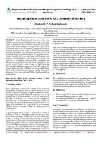
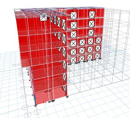
High- rise building facing lateral wind as well as seismic forces,thesewallsused.Impactofwindforcesonreinforced concreteframedconstructionsbecomemoreimportantas the height of the structure rises. Horizontal movement or sway is constrained by codes of practice. Shear wall constructionoftenhavearegularlayoutandelevation.Butin certain structures, the lower floors serve commercial functions and those buildings are distinguished by having biggerplanproportionsatthosefloors.Therearesetbacksin varioussituationsathigherfloorlevels.Buildingswithshear wallsarefrequentlyutilizedforhousingandhaveacapacity of100-500people.
1.1 Shear wall
Shear wall construction often have a regular layout and elevation.But in certainstructures, thelower floorsserve commercialfunctionsandthosebuildingsaredistinguished byhavingbiggerplanproportionsatthosefloors.Thereare setbacksinvarioussituationsathigherfloorlevels.
1.2 Objectives
To determine the G+5 commercial building’s seismic analysisanddesignwithshearwall.
Determiningthebuilding’sstructuralsystem’scapacity tosupportbothverticalandhorizontalloads.
2. METHODOLOGY
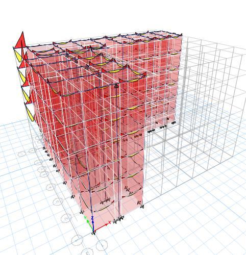
ThisprojectdealswiththeseismicAnalysisandDesignofG +5 commercial building with Shear Walls. Height of each floorandeachtypicalflooris3m.M25concreteandFe500is used. The design criteria are taken into account in accordancewiththeIndianStandardcodeofpractice.IS4562000wasfollowedwhencreatingthedesign.Forthedesign portions,SP16designaidwastakeninconsideration.The structuremustwithstandandconveytothefoundationall impactsofGravityLoadandLateralLoadoperatinginitas integratedsystem.
2.1 Salient features and dimensions of the building
GEOMETRICDATA:
Typeofbuilding : Commercial
Locationofbuilding : Kerala
Typicalstoreyheight : 3m
ELEMENTSIZES:
Column : 230x500mm
Beam : 230x500mm
Shearwall: 200mm
Slabdepth: 125mm
SEISMICDATA:
Location : Kerala
Importancefactor: 0.16
Responsefactor : 5
Typeofsoil : Medium(Type2)
VARIOUSLOADS:
GroundFloorwallload=15.058KN/m
Firstfloorwallload=11.4KN/m
Parapetwallload=4KN/m
Selfweight=1KN/m
Liveload=4KN/m
Staircaseload=9.435KN/m
Floorfinish=1KN/m
PIERDETAILS:
Centroidx=1450mm
Centroidy=15500mm
Length=4000mm
rs=1.15
rc =1.5
Loadcase:EQX
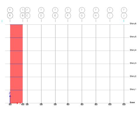
Fig -4: MaximumstoreydisplacementactingduetoEQX
Table -1: Storeyresponsevalue
3. RESULT AND DISCUSSIONS
After analyzing the models, the results from ETABS are discussed in this chapter and shown in figures. After the studyofcommercial structure,simpleparametersusedto determinethestiffnessofthestructurelike displacement, driftandoverturningmomentareevaluated.
3.1 Storey displacement along X and Y direction
Itcanbeoccurredduetomovementinstoreyrespectto foundationofstructure.
Discussion:
IntheabovegraphofMaximumstoreydisplacementacting duetoEQX,thexdirectiondisplacementhighlightedbyblue colourwhereasydirectiondisplacementbyred.Thegraph showsthedisplacementfrombasetotopstorey.Fromthe graphwecanobtainthatMaximumdisplacementisonStorey 5 with a displacement value of 0.035936mm. Also, the Minimumdisplacementonbasewithavalueof0.WhenEQX isappliedXdirectiondisplacementislargerthanYdirection.
FromtheStoreyresponsevaluetable,theresponsevalueof buildingduetoEQXseismicaction frombasetotopstoreyis given. In X direction, response value of base to storey 6 is samewithavalueof0.000001mm.InYdirection,response
valueofbaseis0andresponsevalueofstorey6is2.652E07mm.
Loadcase:EQY
Fig -5: MaximumstoreydisplacementactingduetoEQY
Table -2: Storeyresponsevalue
FromtheStoreyresponsevaluetable,theresponsevalueof buildingduetoEQYseismicaction frombasetotopstoreyis given. In X direction, response value of base is 0 and responsevalueofstorey6is1.698E-03mm.InYdirection, responsevalueofbaseis0andresponsevalueofstorey6is 1.62E-02mm.
3.2 Storey drift along x and y direction
It is lateral displacement of a multistory buildings uppermostlevelwithrespecttolower.
Loadcase:EQX
IntheabovegraphofMaximumstoreydisplacementacting duetoEQY,thexdirectiondisplacementhighlightedinblue colourandydirectiondisplacementbyred.Graphshowsthe displacement from base to top storey. From the graph we canobtainthatMaximumdisplacementisonStorey5witha displacement value of 0.040262mm. Also, the Minimum displacementonbasewithavalueof0.WhenEQYisapplied YdirectiondisplacementislargerthanXdirection.
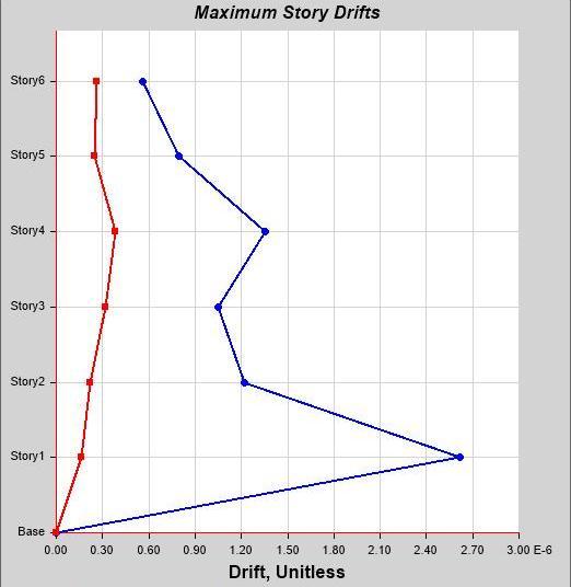
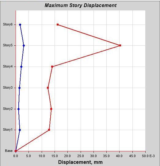
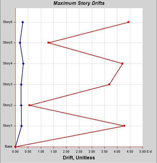
Fig -6: MaximumstoreydriftactingduetoEQX
Table -3: Storeyresponsevalue
Discussion:
In the above graph of Maximum storey drift acting due to EQX,thex directiondrifthighlightedbybluecolourwhereas ydirectiondriftbyred.Graphshowsthedriftfrombaseto top storey. From the graph we can obtain that Maximum driftisonStorey1withadriftvalueof0.000003.Also,the Minimum drift on base with a value of 0. When EQX is appliedXdirectiondriftislargerthanYdirection.
FromtheStoreyresponsevaluetable,theresponsevalueof buildingduetoEQXseismicaction frombasetotopstoreyis given. In X direction, response value of base is 0 and response value of storey 6 is 0.000001. In Y direction, responsevalueofbaseis0andresponsevalueofstorey6is 2.652E-07.
Loadcase:EQY
Discussion:
In the above graph of Maximum storey drift acting due to EQY,thexdirectiondrifthighlightedbybluecolourwhereas ydirectiondriftbyred.Graphshowsthedriftfrombaseto top storey. From the graph we can obtain that Maximum driftisonStorey6withadriftvalueof0.000004.Also,the Minimum drift on base with a value of 0. When EQY is appliedYdirectiondriftislargerthanXdirection.
3.3 Storey stiffness
Loadcase:EQX
Fig -7: MaximumstoreydriftactingduetoEQY
Table -3: Storeyresponsevalue
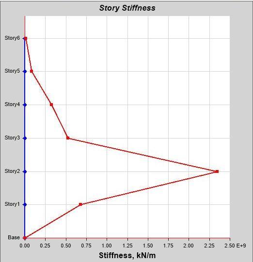
Fig -8: StoreystiffnessactingduetoEQX
Discussion:
IntheabovegraphofMaximumstoreystiffnessactingdueto EQX, the x direction stiffness highlighted by blue colour whereas y direction stiffness by red. Graph shows the stiffness from base to top storey. From the graph we can obtainthatMaximumstiffnessisonStorey2withastiffness valueof1.76E+9KN/m.Also,theMinimumstiffnessonbase withavalueof0.
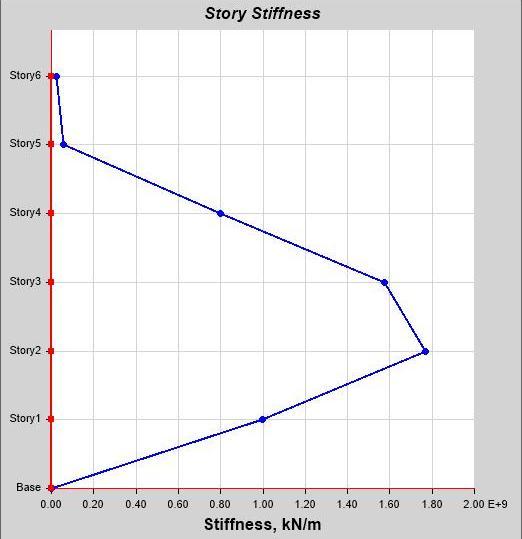
Loadcase:EQY
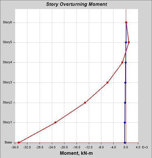
Discussion:
In the above graph of Overturning moment acting due to EQX, the x direction stiffness highlighted by blue colour whereas y direction stiffness by red. Graph shows the moment from base to top storey. From the graph we can obtainthatmomentisonStorey5withamomentvalueof 947.63 KN-m. Also, the Minimum moment on base with a value of -34.7E+3 KN-m. When EQX is applied X direction momentislargerthanYdirection.
Loadcase:EQY
Fig -9: StoreystiffnessactingduetoEQY
Discussion:
IntheabovegraphofMaximumstoreystiffnessactingdueto EQY, the x direction stiffness highlighted by blue colour whereas y direction stiffness by red. Graph shows the stiffness from base to top storey. From the graph we can obtainthatMaximumstiffnessisonStorey2withastiffness valueof2.34E+9KN/m.Also,theMinimumstiffnessonbase withavalueof0.WhenEQYisappliedYdirectionstiffnessis largerthanXdirection.
3.4 Storey overturning moment
Loadcase:EQX
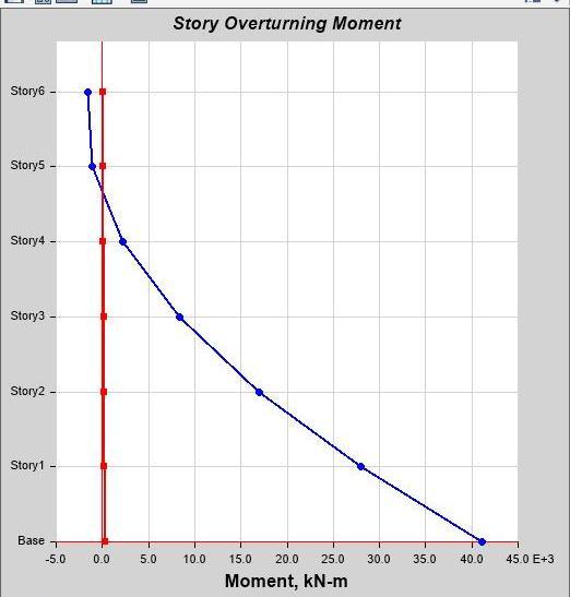
Fig -10: StoreyoverturningmomentduetoEQX
Discussion:
In the above graph of Overturning moment acting due to EQY,xdirectionmomenthighlightedbybluecolourwhereas ydirectionmomentbyred.Graphshowsthemomentfrom base to top storey. From the graph we can obtain that Maximum moment is on base with a moment value of 41.1E+3KN-m.Also,theMinimummomentonstorey6with a value of -1.5 KN-m. When EQY is applied Y direction momentislargerthanXdirection.
4. CONCLUSIONS
Thefollowingconclusionsaremadefromthestudy:
Inthisproject,ETABSsoftwareisusedforseismic analysis and design of G+5 commercial building with shear wall. The amount of time spent on analysis and design is reduced with the use of ETABSsoftware.
Inthisstudy,itispossibletolimitthedamagethat can result from wind and earthquake forces becauseshearwallsareconstructedatpotential deflectionsite.
Thestudyfindingsindicatethatwhencomparedto bareframes,shearwallarrangementsprovidethe highestperformanceforbuildingfeaturessuchas storeydisplacement,interstorydrift,storeyshear etc.
When compared to frame structures shear wall structureshavelessstoreydriftanddisplacement.
A good technique to increase ductility and obtain more stable behavior is to confine concrete in shearwalls.Asaresult,tohaveasuitabledesign, designer is free to increase the degree of axial stress.
4.1 Scope of future study
For further studies, wecan identify the various places for placement ofshearwall for betterlimitingpotential harm from seismic and wind seismic factors at all possible deflectionposition.Also,thestudycanalsobeexpandedto includeanalysisonsteelframes.
REFERENCES
[1] Medaboyini Chandrasekharashok, Shaik Rehman, S Zubeeruddin, “Design And Analysis Of Shear Walls”, International Journal of Research (IJR), e-ISSN: 2348795X,p-ISSN:2348-6848,Vol.8,Issue3March-2021.
[2] Kusuma.S,Dr.E.RameshBabu,“SEISMICANALYSISOF MULTISTORY BUILDING USING ETABS WITH COMPARISONOFRESPONSESPECTRUMMETHODAND TIME HISTORY METHOD”, Journal of Emerging Technologies and Innovative Research (JETIR), ISSN: 2349-5162,Vol.7,Issue5,May-2020.
[3] Richa Gupta, AlfiaBano, “Performance Evaluation of VariousShapesofShearWallusingResponseSpectrum Analysis”, International Journal of Recent Technology andEngineering(IIJRTE),ISSN:2277-3878,Vol.8,Issue 1,May-2019.
[4] TarunaRKamble,Dr.G.D.Awchat,“SeismicAnalysisand Design of Multi-Storied RC Building Using STAAD Pro and ETABS”, International Journal of Innovations in EngineeringandScience(IJIES),e-ISSN:2456-2018,Vol. 3,Issue8,2018.
[5] Abdul Sami Siddiqui, Mohd Abdul Naveed, MD. Imranuddin, Nayeem Baig, Mohd Avez, Mohd Arshad Lateef, “Analysis of Design of Multistory Building
(C+G+10)byShearwallDesignbyOptimizationusingETabs”, International Journal of Scientific Engineering andTechnologyResearch(IJSETR),ISSN:2319-8885,Vol. 7,Issue4,April-2018.
[6] M. Tholkapiyan, A. Mohan, “BEHAVIOUR OF SHEAR WALL IN EARTH QUAKE RESISTANT STRUCTURES”, International Journal ofAdvancedResearchTrendsin EngineeringandTechnology(IJARTET),p-ISSN:23943777,e-ISSN:2394-3785,Vol.5,Issue12,April2018.
[7] AliKifahKadhum,KhattabSaleemAbdul-Razzaq,“Effect of seismic load on reinforced concrete multistory buildingeconomicalpointofview”,InternationalJournal ofCivil EngineeringandTechnology(IJCIET), p- ISSN: 0976-6308, e- ISSN: 0976-6316, Vol. 9, Issue 11, November2018.
[8] D. Shabintaj, Dr. C Rama Chandrudu, Syed Rizwan, “Comparative Study on the Analysis of Commercial BuildingwithandWithoutShearwallbyUsingETABS”, International Journal of Scientific Research in Science andTechnology(IJSRST),p-ISSN:2395-6011,e-ISSN: 2395-602X,Vol.4,Issue5,March-April2018.
[9] RagyJose,RestinaMathew,SandraDevan,Sankeerthana Venu, Mohith Y, “ANALYSIS AND DESIGN OF COMMERCIALBUILDINGUSINGETABS”,International ResearchJournalofEngineeringandTechnology(IRJET), e-ISSN:2395-0056,p-ISSN:2395-0072,Vol.4,Issue6, June-2016.
[10] DurgeshNevel,R.P.Patil,“SurveyPaperonAnalysisof FlatSlabRestingonshearwalls”InternationalResearch JournalofEngineeringandTechnology(IRJET),e-ISSN: 2395-0056, p-ISSN: 2395-0072, Vol. 3, Issue 5 May2016.
[11] M.Pavani,G.NageshKumar,Dr.SandeepPingale,“Shear WallAnalysisandDesignOptimizationInCaseofHigh Rise Building Using Etabs (software)” International Journal ofScientificand EngineeringResearch(IJSER), ISSN:2229-5518,Vol.6,Issue1,January-2015.
[12] HimaleeRahangdale,S.R.Satone,“DesignAndAnalysis Of Multistoreied Building With Effect Of Shear Wall”, International Journal of Engineering Research and Applications(IJREA),ISSN:2248-9622,Vol.3,Issue3, May-Jun,2013.
[13] P.P.Chandurkar,Dr.P.S.Pajgade,“SeismicAnalysisof RCC Building with and Without Shear Wall”, International Journal of Modern Engineering Research(IJMER),ISSN:2249-6645,Vol.3,Issue3,MayJune2013.