STRENGTH ASSESSMENT OF REINFORCED CONCRETE STRUCTURE BY NON-DESTRUCTIVE TESTING
KATAM MALAVIKA 1 , Dr C. SASHIDHAR2
1 PG(Structural Engineering) Student, JNTUA College of Engineering(Autonomous),Anantapur, India

2, Professor, JNTUA University, Anantapur, India
Abstract - Non-destructive testing of concrete is a method to obtain the compressive strength of concrete from the existing structures. This test provides immediate results and actual strength of concrete structure. Non-destructive testing causes minimal damage to the structure on which the test is being performed. The types of non destructive tests to be performed are Rebound hammer test, Ultra sonic pulse velocity test, Carbonation test. The area of building of which testing is to be done is 750 square feet. It was constructed in the year 1996 and the reinforcement of the building is exposed to the atmosphere due to spalling of concrete. The objective is to find out structural stability of the structure by non-destructive testing and give rehabilitation procedures if necessary.
Key Words: NON DESTRUCTIVE TEST(NDT),REBOUND HAMMER,ULTRASONIC PULSE VELOCITY,CARBONATION DEPTH)
1. INTRODUCTION
Concrete is a composite material produced from the combinationofcement,fineaggregate,coarseaggregateand waterintheirrelativeproportion.Itisaubiquitousbuilding materialbecauseitsconstituentsarerelativelycheap,and readily available. In addition to that, concrete in its fresh statehastheabilitytobemouldedintoanydesiredshape and size. The strength of concrete is its most important property(especiallywhenneededforstructuralpurposes) alongside its durability. Deterioration or damage of reinforcedconcretemaybecausedduetoseveralreasons andisnowadayscommonlyobservedbecauseofimproper construction techniques. Deterioration of concrete has significant effect on the performance and serviceability of structures.Manyfactorscancontributetothedeterioration of concrete structures such as; poor construction, overloading, aging, corrosion of steel, chemical reactions, naturaldisasters,etc.Unfortunately,damagepropagationis atimedependentprocesswithseriouseffectonstructural capacity and durability. Deterioration signs can be visible suchasconcretecrackingorexcessivedeflectionswhichcan be detected with visual inspection. In these cases, the concretememberhasprobablyreachedsignificantlevelof damage. Early detection of damage minimizes the repair costsandpreservestheservice-lifeofthestructure.
NDT of concrete is of great scientific and practical importanceespeciallytheneedforqualitycharacterization
ofdamagedconstructionsmadeofconcrete.Itsimportance canalsobeseeninthedesireforaproposedchangeofusage orextensionofastructure,acceptabilityofastructurefor purchaseorinsurance,assessmentofthequalityorintegrity of the repairs, monitoring of strength development in relationtoformworkstripping,curing,pre-stressingorload application. This research is to assess the condition of existing reinforced concrete structure by non destructive testingandrecommendrehabilitationprocedures.
2. LITERATURE REVIEW
Pardeep K. Gupta, Niharika Gupta and Amandeep Singh conductedexperimentalstudyonparametersaffectingthe resultstoestimateitsreliability,theoriginalSchmidtcurve provided by the producers along with the hammer and is used in Structural Engineering Applications. This paper discussed an extensive research, and application, of this technique to assess the compressive strength of a raft foundationofagovernmentbuilding,showingthatseveral phenomena strongly affect the test: moisture content, maturity,stressstateamongtheothers.Thepresentpaper gives a combined test method for compressive strength assessmentbyasuitablecorrelationbetweenthetwotestsReboundHammerTestandthetestbycompressivetesting machine. The results were verified using compression testingmachineandthesewerereliable.Itisfoundthatthe useofNDTtechniqueslikeReboundHammerTestismuch reliableandcanwellbefittoassessthequalityofconcrete structures.
Naser Alenezi done study to evaluate the structural integrity of a villa located in Kuwait by rebound hammer, UPV tests. The building consists of two storey floors and basementfloor.Thebuildingshowedhugecracksinmostof the concrete structural elements. The recent study of structuralintegrityandevaluationincluded,comparingthe asbuiltwiththedesigndrawings,detailedvisualinspection, evaluating the quality of concrete by using field and laboratory tests and structure analysis to determine the safetyfactors.Problemsencounteredinreinforcedconcrete buildingsarenotlimitedto thosewheretheconcretewas notdesignedfordurability.Itincludesalsoconcretewhich wasnotconstructedforgoodperformanceandfordurability
Volume: 10 Issue: 02 | Feb 2023 www.irjet.net p-ISSN: 2395-0072 © 2023, IRJET | Impact Factor value: 8.226 | ISO 9001:2008 Certified Journal | Page583
-***
International Research Journal of Engineering and Technology (IRJET) e-ISSN: 2395-0056
3. METHODOLOGY
3.1 REBOUND HAMMER:
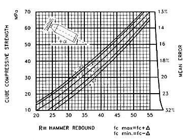
Thereboundhammermethodcouldbeusedfor:
i)Evaluationofexpectedcompressivestrengthofconcrete
usingappropriatecorrelationbetweenrestitutionindexand compressivestrengthii)Evaluationofconcretehomogeneity
iii) Evaluation of concrete quality in relation to standard requirements and One concrete element related to the element.
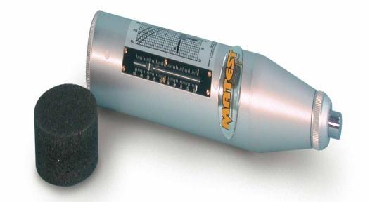
3. 2 ULTRASONIC PULSE VELOCITY:
It can be determined using the ultrasonic pulse velocity method.
(i)ConcreteHomogeneity
(ii) Presence of cracks, voids and other imperfections, changesinconcretestructurethatmayoccurovertime
(iii)ConcreteQualityStandardRequirements,
(iv)Qualityofoneconcreteelementrelativetoanother.
3.3 CARBONATION TEST:
OBJECT:
Thecarbonationtestcouldbeusedfor:
(i)Tofindifcarbonationhasoccurred.
(ii)ToknowapproximatepHvalue.
PRINCIPLE:
Carbonationofconcreteoccurswhenthecarbondioxide,in the atmosphere in the presence of moisture, reacts with hydrated cement minerals to produce carbonates, e.g. calcium carbonate. The carbonation process is also called depassivation. Carbonation penetrates below the exposed surfaceofconcreteextremelyslowly
A1%phenoptaleinsolutionispreparedbydissolving1gof phenoptalein in 90 ml of ethanol. Distilled water is then addedtobringthesolutionto100cc.Thephenolphthalein solutionissprayedonthecorejusttakenout,andthedepth of the uncoloured layer (carbonized layer) from the outer surface is measured in millimetres at or 8 points, and the averageistaken.Ifthetestisperformedinaborehole,first airbrush the hole to remove dust, then again measure the depthofthecleanlayerator8locationsandaverage.Ifthe concretestillretainsitsalkalinity,thecolouroftheconcrete willturnpurple.Whencarbonationoccurs,thepHchanges to7(ieneutralstate)andnocolourchangeoccurs
Volume: 10 Issue: 02 | Feb 2023 www.irjet.net p-ISSN: 2395-0072 © 2023, IRJET | Impact Factor value: 8.226 | ISO 9001:2008 Certified Journal | Page584
Figure 3.1: Rebound Hammer
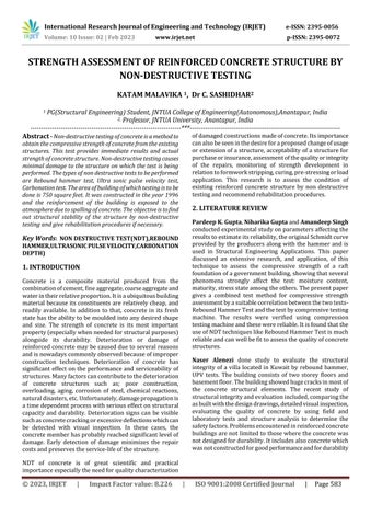
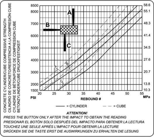
Figure 3.2: Graph on Rebound Hammer
Fig 3.3: Ultrasonic Pulse Velocity Testing Machine
Table 3.1: Velocity Criterion for Concrete Quality Grading
Pulsevelocity(m/s) Concretequalitygrading Above4500 Excellent 3500–4500 Good 3000–3500 Medium Lessthan3000 Doubtful
International Research Journal of Engineering and Technology (IRJET) e-ISSN: 2395-0056
4. BUILDING DETAILS AND CONDITION ASSESSMENT
BUILDING DETAILS :
• AREA=750sqft
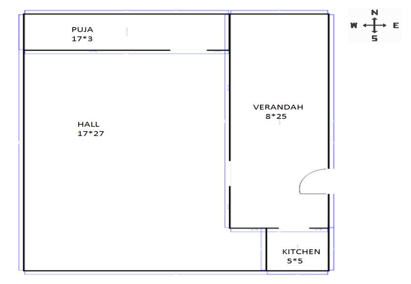
• Constructedintheyear1996
• Thicknessofslab120cm
4.1 CONDITION ASSESSMENT:
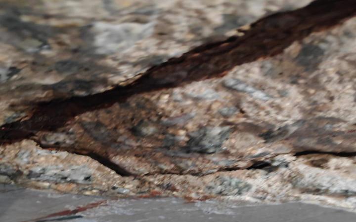
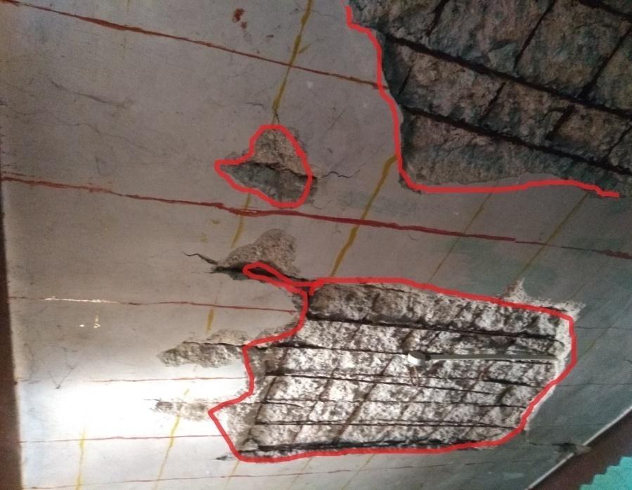
On visual inspection it is seen that spalling has occurredinmanypartsofslab.
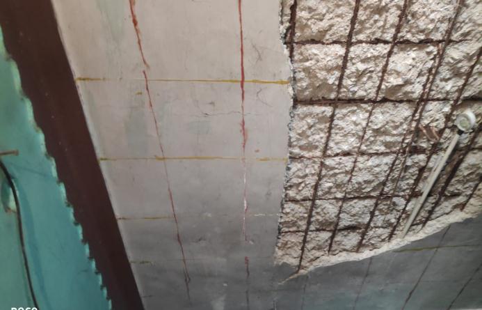
Covertillthereininforcementisremovedinmany areas.
Reinforcementisexposedtoatmosphereinportions ofslab,10-20%reinforcementisvisible
Full extent of carbonation is observed by the full discoloredportionoftheconcrete,whichindicates severe carbonation took place in the structure concreteconsequentlythereinforcementembedded init.
MinimumgradeofconcreteforReinforcedCement ConcretestructureisM15
5. TESTS PROCEDURE AND VALUES
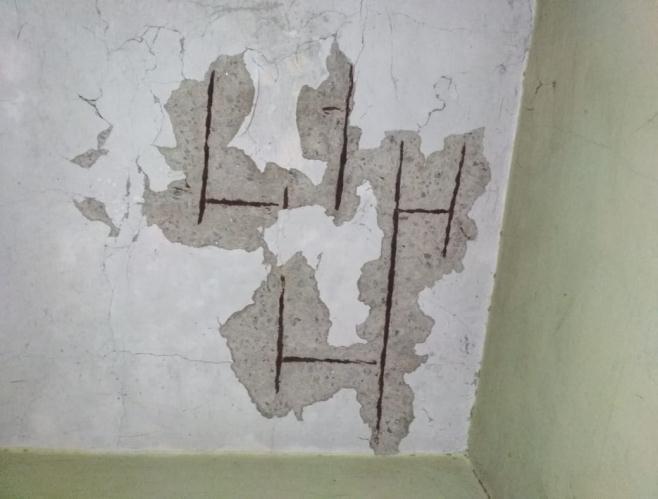
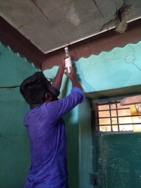
5.1 PAINTING OF GRID ON THE CEILING
A grid shaped pattern is drawn on the ceiling .The grid is drawnformarkingnodesontheceiling.Polyesterenethread isdippedinpaintandpacedatintervalsof1feetinbothx andydirections.Thepointofintersectioningridistakenas nodeandeachsquareformedisknownaselement.
5.2
Thevaluesatarenotedandthenconvertedintotheir respectivecubecompressivestrengthbyusingthegraphs givenonthereboundhammer.
Volume: 10 Issue: 02 | Feb 2023 www.irjet.net p-ISSN: 2395-0072 © 2023, IRJET | Impact Factor value: 8.226 | ISO 9001:2008 Certified Journal | Page585
Figure 4.1:Plan of The Building
Figure 4.2 :Damaged Slab
Figure 5.1: Grid pattern on the ceiling
REBOUND HAMMER TEST VALUES
International Research Journal of Engineering and Technology (IRJET) e-ISSN: 2395-0056
Volume: 10 Issue: 02 | Feb 2023 www.irjet.net p-ISSN: 2395-0072 © 2023, IRJET | Impact Factor value: 8.226 | ISO 9001:2008 Certified Journal | Page586
Graph 5.2: Rebound number Vs Compressive strength
Figure 5.3: Rebound Hammer Test
Nodes Rebound Number Compresssive Strength (N/mm2) 1 41 2933 2 38 2484 3 32 1725 4 34 1955 5 38 2484 6 37 23.46 7 34 1955 8 37 2346 9 34 1955 10 37 23.46 11 38 2484 12 35 2070 13 37 2346 14 37 23.46 15 36 22.08 16 42 31.05 17 39 26.22 18 33 18.40 19 28 12.63 20 38 24.84 21 44 34.50 22 40 27.60 23 30 14.95 24 38 24.84 25 32 17.25 26 32 17.25 27 34 19.55 28 36 22.08 29 44 34.50 30 46 37.95 31 31 16.10 32 30 14.95 33 31 16.10 34 27 11.46 35 35 20.70 36 31 16.10 37 38 24.84 38 26 10.30 39 28 12.63 40 31 16.10 41 26 10.30 42 33 18.40 43 38 24.84 44 34 19.55 45 38 24.84 46 30 14.95 47 28 12.63 48 26 10.30 49 27 11.46 50 30 14.95 51 40 27.60 52 36 22.08 53 32 17.25 54 35 20.70 55 28 12.63 56 29 13.80 57 30 14.95 58 26 10.30 59 28 12.63 60 38 24.84 61 38 24.84 62 30 14.95 International Research Journal of Engineering and Technology (IRJET) e-ISSN: 2395-0056
Table 5.1: Rebound hammer test values
5.3 Ultrasonic pulse velocity test
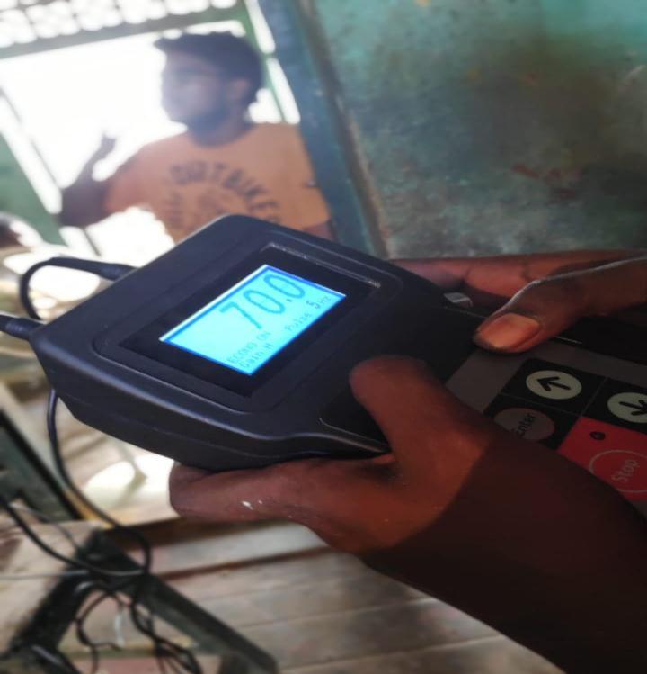
Distance is measured between elements (ie 1 feet) and velocityiscalculatedbyusingtherelationgivenasfollows
HereV=ultrasonicpulsevelocity
d=distancebetweentwoelements
t=timetakenforpulsetotravel

International Research Journal of Engineering and Technology (IRJET) e-ISSN: 2395-0056 Volume: 10 Issue: 02 | Feb 2023 www.irjet.net p-ISSN: 2395-0072 © 2023, IRJET | Impact Factor value: 8.226 | ISO 9001:2008 Certified Journal | Page587 63 34 19.55 64 32 17.25 65 34 19.55 66 34 19.55 67 32 17.25 68 32 17.25 69 28 12.63 70 26 10.30 71 32 17.25 72 30 14.95 73 42 31.05 74 26 10.30 75 31 16.10 76 35 20.70 77 33 18.40 78 37 23.46 79 31 16.10 80 27 11.46 81 36 22.08 82 28 12.63 83 26 10.30 84 32 17.25 85 30 14.95 86 30 14.95 87 32 17.25 88 28 12.63 89 34 19.55 90 30 14.95 91 36 22.08 92 36 22.08 93 30 14.95 94 30 14.95 95 30 14.95 96 36 22.08 97 33 18.40 98 28 12.63 99 32 17.25 100 37 23.46 101 29 13.80 102 28 12.63 103 36 22.08 104 32 17.25 105 32 17.25 106 40 27.60 107 28 12.63 108 38 24.84 109 38 24.84 110 38 24.84
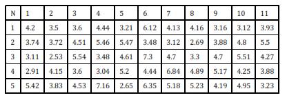
Nodes Time(microsec) Distance (m) Ultra Sonic Pulse Velocity(Km/S) 1 72.56 0.3048 4.2 2 3 81.44 0.3048 3.74 4 5 98.00 0.3048 3.11 6 7 104.55 0.3048 2.91 8 9 56.23 0.3048 5.42
Table 5.2: Ultrasonic pulse velocity values
Figure 5.4:Ultrasonic pulse velocity test
International Research Journal of Engineering and Technology (IRJET) e-ISSN: 2395-0056
Volume: 10 Issue: 02 | Feb 2023 www.irjet.net p-ISSN: 2395-0072
ISO
Certified
10 11 79.44 0.3048 3.83 12 13 73.44 0.3048 4.15 14 15 120.33 0.3048 2.53 16 17 81.74 0.3048 3.72 18 19 86.89 0.3048 3.5 20 21 84.66 0.3048 3.6 22 23 67.55 0.3048 4.51 24 25 54.96 0.3048 5.54 26 27 84.55 0.3048 3.6 28 29 67.24 0.3048 4.53 30 31 42.56 0.3048 7.16 32 33 100.00 0.3048 3.04 34 35 87.47 0.3048 3.48 36 37 55.79 0.3048 5.46 38 39 68.54 0.3048 4.44 40 41 94.66 0.3048 3.21 42 43 55.70 0.3048 5.47 44 45 66.10 0.3048 4.61 46 47 58.56 0.3048 5.2 48 49 114.86 0.3048 2.65 50 51 47.98 0.3048 6.35 52 53 68.54 0.3048 4.44 54 55 41.73 0.3048 7.3 56 57 87.45 0.3048 3.48 58 59 49.77 0.3048 6.12 60 61 73.66 0.3048 4.13 62 63 97.66 0.3048 3.12 64 65 64.77 0.3048 4.7 66 67 44.56 0.3048 6.84 68 69 58.77 0.3048 5.18 70 71 58.21 0.3048 5.23 72 73 62.31 0.3048 4.89 74 75 92.11 0.3048 3.3 76 77 113.10 0.3048 2.69 78 79 73.22 0.3048 4.16 80 81 96.22 0.3048 3.16 82 83 78.55 0.3048 3.88 84 85 64.77 0.3048 4.7 86 87 58.88 0.3048 5.17 88 89 72.66 0.3048 4.19 90 91 61.55 0.3048 4.95 92 93 71.55 0.3048 4.25 94 95 55.22 0.3048 5.51 96 97 63.42 0.3048 4.8 98 99 97.55 0.3048 3.12 100 101 77.44 0.3048 3.93 102 103 55.33 0.3048 5.5
© 2023, IRJET | Impact Factor value: 8.226 |
9001:2008
Journal | Page588
6. RESULTS AND DISCUSSIONS
Averagecompressivestrength=19.02N/mm2
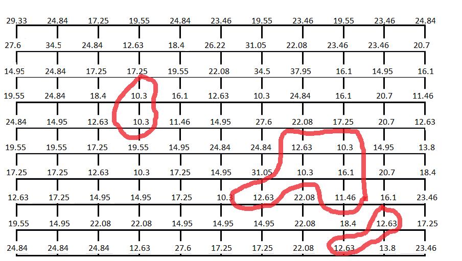
Carbonation test is performed at the nodes where the compressivestrengthislow.Asseenfromtheabovegraphs lowcompressivestrengthisobservedatthenodesand itis shownashighlightedportioninthefiguresgivenbelow.
Volume: 10 Issue: 02 | Feb 2023 www.irjet.net p-ISSN: 2395-0072 © 2023, IRJET | Impact Factor value: 8.226 | ISO 9001:2008 Certified Journal | Page589 104 105 71.22 0.3048 4.27 106 107 78.44 0.3048 3.88 108 109 94.22 0.3048 3.23 110
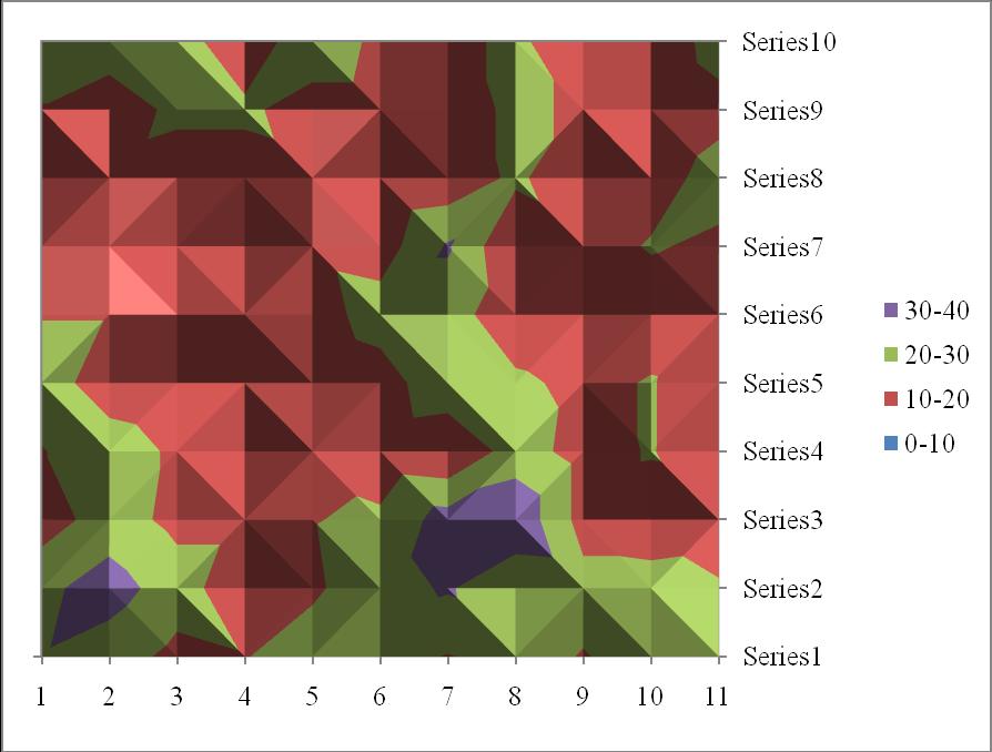
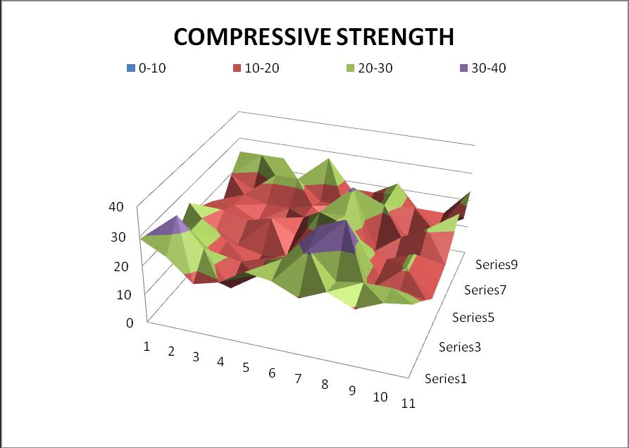
6.1 COMPRESSIVE STRENGTH
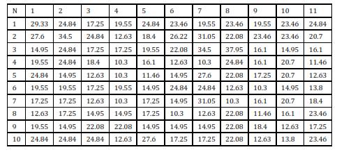
Table 6.1: Compressive strength values in nodal representation
Graph 6.1: 3D Surface graph of compressive strengths
Graph 6.2: Plane surface graph of compressive strength
6.2 CARBONATION TEST
International Research Journal of Engineering and Technology (IRJET) e-ISSN: 2395-0056
Figure 6.1: Weak Compressive strength zone
Carbonationtestisperformedatthenodes41,48,78,63,83, 85,84,90,103byspraying1%phenolphthaleinsolution.
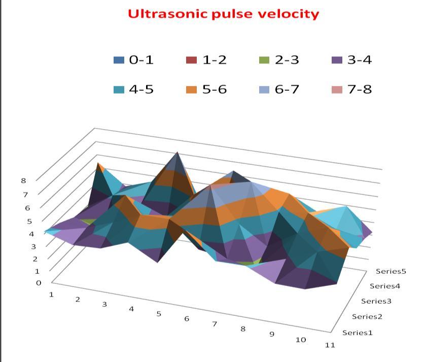
Average ultrasonic pulse velocity =4.3650 Km/sec
When performed corbonation test it is clearly seen that colourhasnotchangedwhen phenolphthaleinissprayedat the nodes. Hence we can conclude that carbonation has occurred.
6.3
Table
7. CONCLUSION AND RECOMMENDATIONS
CONCLUSION:
Average compressive strength (19.02 N/mm2) is abovetheallowablelimitasperIS456:2000 .
Average ultrasonic pulse velocity value (4.3650 Km/s)isexcellentasperIS13311:1992(part-2).
Carbonationhasoccurredatnodes41,48,78,63,83, 85,84,90,103.
Highest compression strength values are seen at nodes1,13,18,29,30,73,95.
Lowest compressive strength values are seen at nodes41,48,78,63,83,85,84,90,103.
Highestultrasonicpulsevelocityvalueis7.3Km/s betweenelements55and56.
Highest compressive strength is 37.95 N/mm2 at node30.
RECOMMENDATIONS:
• Ifthecostofrehabilitationexceeds50%ofrecasting thenrehabilitationisavoidedasitslifeismaximum of10years.
Volume: 10 Issue: 02 | Feb 2023 www.irjet.net p-ISSN: 2395-0072 © 2023, IRJET | Impact Factor value: 8.226 | ISO 9001:2008 Certified Journal | Page590
Figure 6.2: Weak Compressive strength zone
Figure 6.3: Carbonation test
ULTRASONIC PULSE VELOCITY TEST
6.2: Ultrasonic pulse velocity values in nodal representation
Graph 6.4: 3D Surface graph of ultrasonic pulse velocity
International Research Journal of Engineering and Technology (IRJET) e-ISSN: 2395-0056
• RehabilitationProcedureforrestoringdamagedRCC slabbygroutingsystemsincludingcracks,stitching withadditionalsteelreinforcement.
Removetheplasteringofcoverconcrete
Makegroovesandzigzaglinestocracked lines
Drillholesforpressuregrouting
Cleandebrisusingaircompressor
Fixthepolymercoatedsteelrodoverorin placeofcorrodedrods
Fixplugmaterialsinthedrillednozzle
Closethegroovesandcracksbyplastering withpolymermodifiedmortar
References
(i) IS13311(part1):1992 non-destructivetesting of concrete-methodsoftestpart1ultrasonic pulsevelocity.
(ii) IS 13311 (part1 ):1992 non-destructive testing of concrete-methodsoftestpart2ReboundHammer.
(iii) Alexandre,B.J.,Glória,G.M.,andAugusto,G.(2013). "Compressive strength evaluation of structural lightweightconcretebynon-destructiveultrasonicpulse velocitymethod".Ultrasonics.
(iv) Reddy K., (2014). “Assessment of strength of Concrete by Non-Destructive Testing Techniques”, International Journal of Engineering and Management Research,Volume4,Issue3,pp.248-256.
(v) Paul J. Tikalsky (2006) . “Overview Of NonDestructiveTestingMethodsOfMaterialsEvaluation”,
(vi) Pardeep K. Gupta, Niharika Gupta and Amandeep Singh. “Case study of strength evaluation of structural concreteusingreboundhammertest”.
(vii) Naser Alenezi . “Strength Evaluation of Existing ReinforcedConcreteStructure”,InternationalConference on Artificial Intelligence, Energy and Manufacturing Engineering(ICAEME'2015)Jan.7-8,2015Dubai(UAE).
(viii)Hua-Peng Chen . “Assessment of concrete damage and strength degradation caused by reinforcement corrosion” , Journal of Physics Conference Series628(1)·July2015.
(ix) HoJaeLee,DoGyeumKim,JangHwaLee,Myoung SukCho .“AStudyforCarbonationDegreeonConcrete usingaPhenolphthaleinIndicator“.
(x) Jelena Savic . “Damage of Concrete and Reinforcement of Reinforced-Concrete Foundations CausedbyEnvironmentalEffects”,InternationalScientific Conference Urban Civil Engineering and Municipal Facilities,SPbUCEMF-2015
Volume: 10 Issue: 02 | Feb 2023 www.irjet.net p-ISSN: 2395-0072 © 2023, IRJET | Impact Factor value: 8.226 | ISO 9001:2008 Certified Journal | Page591
International Research Journal of Engineering and Technology (IRJET) e-ISSN: 2395-0056