STUDY ON STRUCTURAL BEHAVIOUR OF TRANSMISSION LINE TOWER USING GFRP MATERIAL
1, PG Student, Department of Civil Engineering, Excel Engineering College. Komarpalayam ***
Abstract - This thesis deals with the excremental investigation on the properties of GFRP (Glass Fiber Reinforced Polymer) In this Thesis we use the GFRP to find out the behavior of the final product made by this material which is line transmission tower. Due to the rapidpopulationgrowth and rapid urbanization the natural resources are depleting day by day. So the natural aggregates are very hard to obtain. So many people are opting to use the GFRP (Glass Fiber Reinforced Polymer) instead of the conventional iron or steel channels. The cost of conventional iron or steel channels as compared to GFRP is also very high due to the high demand of it in construction works.
GFRP will reduce the quarrying and mining of iron and steel ores thereby reducing the use of natural resources excessively. The land surface can be prevented from any unwanted excavation and hence ecological disturbances will be reduced to conserve the conventional natural iron ore for other important construction works.
The compression and the tensile tests are carriedout inthe thesis to find out the behavior of the different types of the joints and channel sections with different types ofconnections. And the result is carried out and accordingly the conclusion is given
Key Words: GFRP (Glass Fiber Reinforced Polymer), Transmission tower, Urbanization, Construction.
1. INTRODUCTION.
A“compositematerial”ismadeoftwoormoreconstituent materials with different physical and chemical properties. Thecompositecomponentsremainseparateanddistincton a microscopic level withinthefinishedstructure,whichis designedtohavespecificproperties.
FRP(FiberReinforcedPolymer)materialwasfirst usedatthestartofthe20thcenturyasanicheapplication formilitaryuse.Now,FRPcompositematerialsarewidely used in various industries such as aerospace, automotive, construction,sportandrecreation,marineandenergy.

BecauseusingFRPbarstoreplacesteelbarscansignificantly improvethedurabilityandreducethelife-cyclecostsofthe concretestructures,concretestructuresreinforcedwithFRP bars,prestressedFRPbarsandFRPanchorboltsarebeing moreandmoreusedinbridge,offshorestructures,nuclear
reactor engineering, airport pavement, underground constructions and coal mine tunnel structures with the promulgation and implementation of the design specifications.
1.1 VARIOUS TYPES OF FIBERS
1NaturalorOrganicFiber:
Jutefiber

Coirfiber
Bamboofiber
SisalFiber
2InorganicFibers:
Glassfiber
Carbonfiber
Aramidfiber
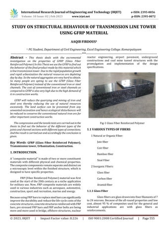
1.1.1 Glass Fiber
Glassfibersareglassdrawnintofinerfilamentsof7 to24microns.Becauseoftheall-roundpropertiesandlow cost, almost 95 % of composites used for the general and industrial applications are with glass fibers as reinforcements.
2 SCOPE
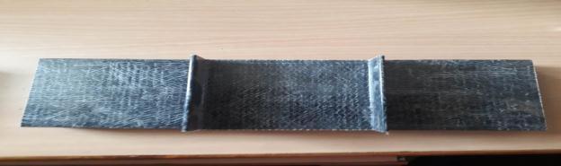
PultrudedsectionsofFiberReinforcedcompositematerial areoneoftheemergingconstructionmaterials.Lightweight, Highstrength,goodcorrosionandfireresistanceincluding Tailor able properties are the attractive features for considering such materials as favourable one by the Engineers,Constructors,Academiciansandotherpersonnel involved.
While there materials are quite frequently used materials in western countries including china in various fields, the momentum in our nation has not yet picked up due to lack of reasonable research in the field. While FRP materials are prevalently used in Aeronautical/Space industries,utilizationinconstructionsectorisveryscarce andlimited.
Transmission tower are vital structures both in powersectoraswellasincommunicationsectorconstructed so far only using conventional metallic angle/channel sections such towers while exposed to adverse environmental conditions undergo gradual/sudden degradation/deterioratedduetocorrosionorotherdefects.
3 MATERIAL PROPERTIES
Composite material made of a polymer reinforced with Fibers.ConsistofthermosettingresinsandglassFiber.The manufacturingprocessinvolvestheadditionpolymerization andstepgrowthpolymerization.theplasticwhichisunder polymerization is mixed with glass Fiber, enhance the strength and elasticity of the plastic .this results in the formationofglassFiberreinforcedplasticsGFRP).
4 CONNECTION DETAILS
4.1 TYPES OF JOINTS
• Buttjoint
• Lapjoint
4.2 TYPES OF CONNECTIONS
• Boltedconnection
• Adhesiveconnection
• CombinedorHybridconnection
4.3 JOINT CONNECTIONS WITH BOLTS
BUTTJOINT-BOLTEDCONNECTION
BUTTJOINT–ADHESIVECONNECTION
LAPJOINT-BOLTEDCONNECTION
LAPJOINT-ADHESIVECONNECTION
4.1.1
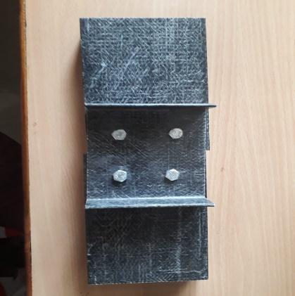
Abuttjointisatechniqueinwhichtwopiecesofmaterials arejoinedbysimplyplacingtheirendstogetherwithoutany specialshaping.Thename‘buttjoint’comesfromthewayof materialisjoinedtogether.Thebuttjointisthesimplestjoint to make since it merely involves cutting the wood to the appropriatelengthandbuttingthemtogether
Alapjointoroverlapjointisajointinwhichthemembers overlap. Lap joints can be used to join wood, plastics and metals.
4.2.1 BOLTED CONNECTION
Toachieveanefficientboltedjointdesign,thestructural twolimitationsaremainlyconsidered.First,compositesare toobrittletobeanalyzedusingtheconventional,fullyplastic methodofdesigningmetallicboltedjointsbecausecomposite fibers fail in a brittle mode at a typical strain level of 2%, whereasductilemetals13%beforefailure,enablingdrastic loadredistributionbetweenthefasteners.Second,theuseof linear elastic analysis is equally inappropriate due to the greatstrengthincreaseresultingfrombeginmicrofailuresin theimmediatevicinityofsmallboltholes.
4.2.2 ADHESIVES
Adhesive is a general term used for substances (e.g., cement,glueandpaste)capableofholdingmaterialstogether by surface attachment. Adhesion is associated with intermolecularforcesactingacrossaninterfaceandinvolves aconsiderationofsurfaceenergiesandinterfacialtensions. Thematerialsbeingjoinedarereferredtoasthe“adherents” or“substrates”.
4.2.3 COMBINED CONNECTION
In combination joints, both adhesives and mechanical fasteners are used. This method of joining composites can provide the joint with greater capacity and reliability. In combined joints, the inherent strengths of the component elements are enhanced to produce a joint that displays significantlyimprovedperformance.
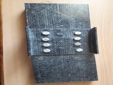
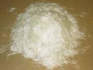
4.3.1 BUTT JOINT-BOLTED CONNECTION
Inbuttjoint,thereisagussetplatesize5cm*10cmused toconnecttherespectivetwoGFRPmaterials.Theminimum available bolts size 6mm is used in this connection .Three typesofconnectionsaremadesuchas4bolted,6boltedand 8boltedwiththesamesizesofgussetplates.
In these connections, also the gusset plates size 5cm*10cmareused.butthesmallchangeofconnectingagent as adhesive (resins) is used .first the two specimens are connectedandfurtherthegussetplatesareprovidingforthe extrasupport.
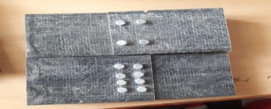
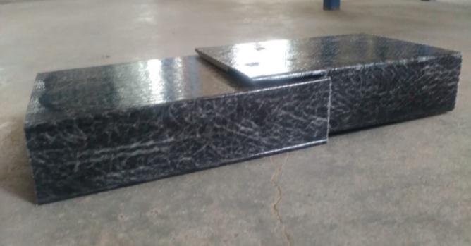
In lap joint, there is a concept of overlapping in the specified size of 5cm of two materials for their respective numberofbolts.4boltedand6boltedconnectionsaremade withoutanyrisk.Butin8boltedlapthereisariskinspacing betweenbolts.
Inlapjoint,thereisasecondchoiceofusingadhesivesas a connecting agent. The overlapping space as like that of gussetplatesize5cm.itisaquickerreactionofconnecting twomaterials.
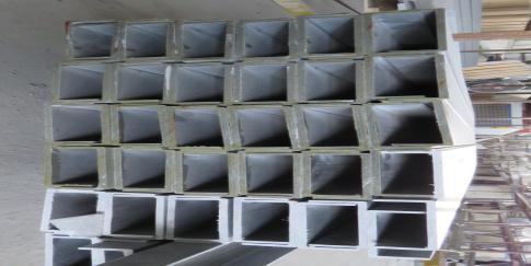
5 EXPERIMENTAL STUDIES
TheVariousConnectionsofChannelSectionsaredone by proper drilling and markings. The connections are tightened by fasteners. The various connections and its descriptionsarementionedbelow.
4. LABORATORY PROCESS
Marking: The required dimensions of hole drillings are initially marked and further specimens are drilled for its desiredshape.
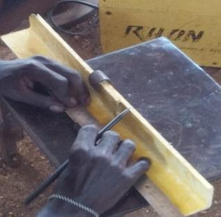

Marking
Cutting: Initiallythespecimensareshapelycutinthesizeof 15cmaslengthforeachtypeofconnections.Dimensionof thewidthofthespecimentakenis50mm.
Table-1DescriptionofChannelSectionanditsconnection
6 RESULTS AND DISCUSSION
6.1 TESTING OF GRPF CHANNEL SECTION
ThefollowingarethevariouspropertiestestoftheGFRP channelsectionanditsconnectiontests.
6.1.1 COMPRESSION TEST
Cutting
Drilling: Theminimumsizeofdrillingismadethatis6mm boltedholes.
CompressiontestareperformedaccordingtoASTMD695 to evaluate the behavior of the material when it is subjectedtocompressiveload.Samplesareplacedbetween twoparallelplatensinauniversaltestingmachineandthen slowlycompressedatlowanduniformrate.Themaximum loadisrecordedaswellasstress/straindata.Thematerial compressivemoduluscanbeobtainedusingthistest.
Drilling
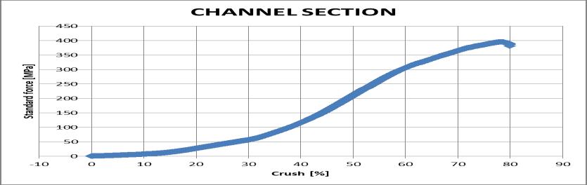
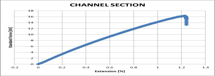
CompressiontestofChannelSection
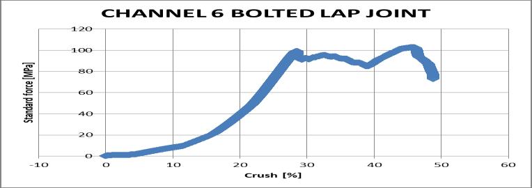
Compressiontestof6BoltedChannelLapJoint
Compressiontestof4BoltedChannelButtJoint
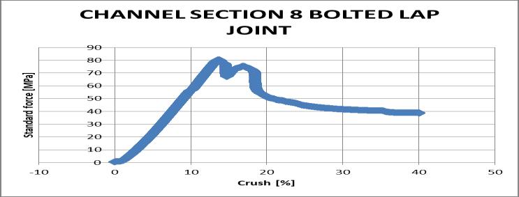
Compressiontestof8BoltedChannelLapJoint
Compressiontestof6BoltedChannelButtJoint
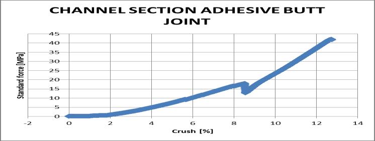
CompressiontestofChannelAdhesiveButtJoint
Compressiontestof8BoltedChannelButtJoint
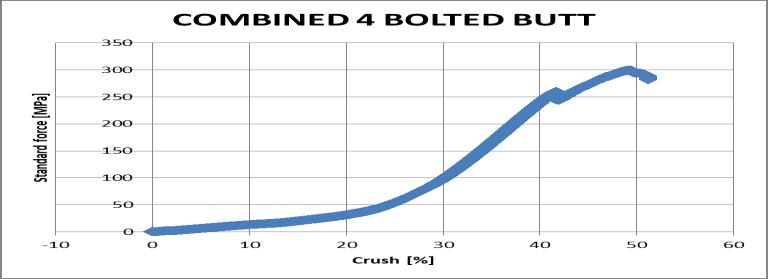
CompressiontestofChannelCombined4boltedButtJoint
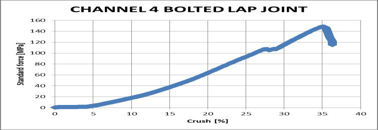
Compressiontestof4BoltedChannelLapJoint
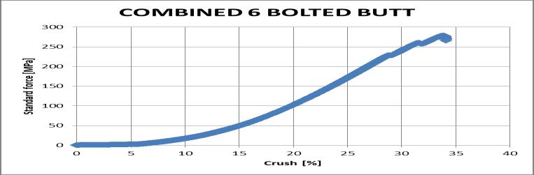
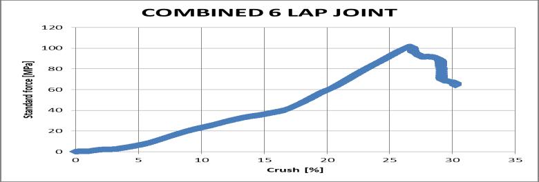
CompressiontestofChannelCombined6boltedButtJoint
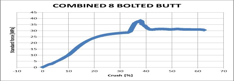
CompressiontestofChannelCombined8boltedButtJoint
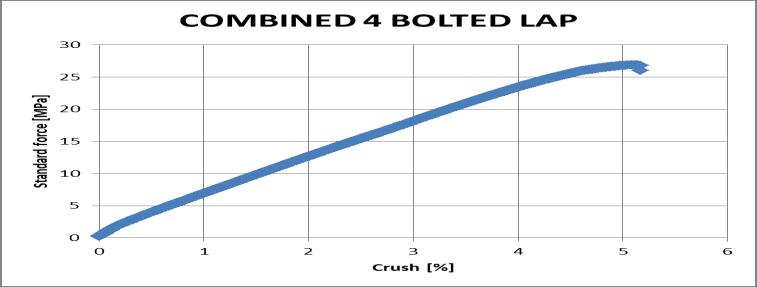
CompressiontestofChannelCombined4boltedLapJoint
6.2 DISCUSSION
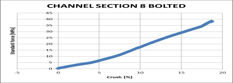
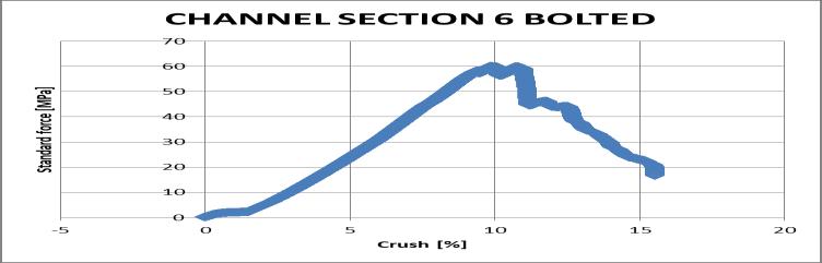
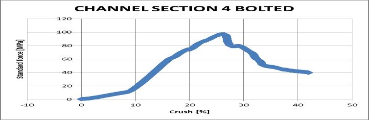
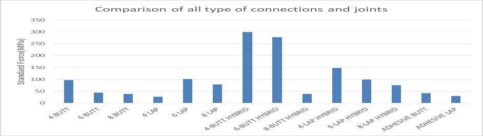
According to our experiments, the various connections of channel sections based on the bolts and adhesive are taken into account by the crush (%) and its StandardForce(MPa).Theabovementionedgraphsgivethe values of the various connections. This shows that the HybridconnectionsexperiencemoreForces.
6.2.1 THE HYBRID CONNECTION
CompressiontestofChannelCombined
6boltedLapJoint
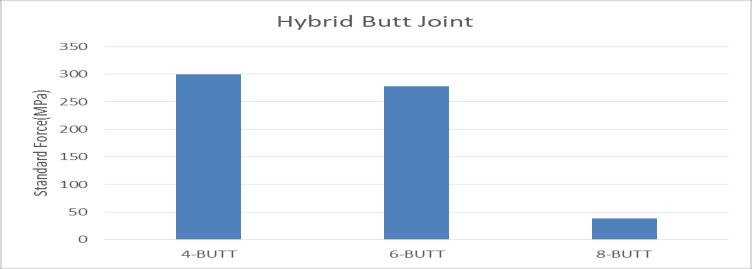
TheHybridbuttjointsofvariousboltedconnection are graphed by standard forces on the Vertical axis. This showsthattheforcesexertedby4-boltedHybridbuttjoints arehighascomparedtotheotherconnections.
CompressiontestofChannelCombined
6.1.2 TENSILE TEST
8boltedLapJoint
TensiontestsareperformedaccordingtoASTMD-3039 using coupons placed in a universal testing machine. A tensileloadisslowlyanduniformlyappliedtothesample untilitfails.Anextensometermaybelocatedontheareato measure the extension as the load is applied. The load magnitude and extension are recorded. Values for tensile strengthandtensilemoduluscanbeobtainedwiththetest can be performed on new and aged samples to determine anychangesinproperty
ComparisonofHybridButt468boltedJoint

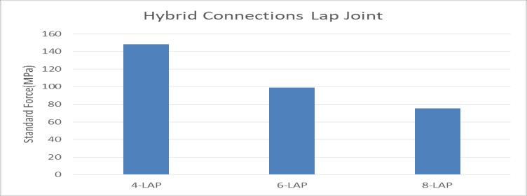
TheHybridLapjointsofvariousboltedconnection are graphed by standard forces on the Vertical axis. This showsthattheforcesexertedby4-boltedHybridLapjoints arehighascomparedtotheotherconnections.
6.2.2
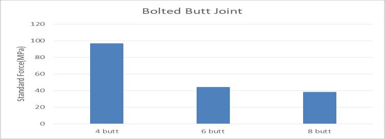
Theboltedconnectionsofbuttjointsaregraphedby standard forces on the Vertical axis. This shows that the forcesexertedby4-boltedbuttjointsarehighascompared totheotherconnections.
Byanalyzingallthesectionsthemaximumforcethat experienced by all the various connections are charted below.
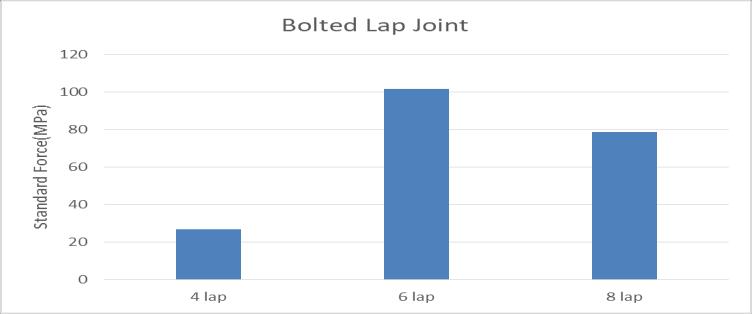
Theboltedconnectionsoflapjointsaregraphed bystandardforcesontheVerticalaxis.Thisshowsthatthe forcesexertedby6-boltedlapjointsarehighascompared totheotherconnections.
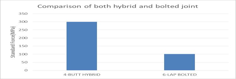
Fromthefourgraphsthe4-boltedCombinedButt Jointandthe6boltedLapjointsarecomparedandPlotted intheSameGraph.Thisclearlyshowsthatthe4-bolted combinedButtjointshavehighvalues.
7 CONCLUSIONS
There is an increasing demand for alternatives to conventional construction materials in infrastructural applications in the present days. In this front, Fiber Reinforced Plastics (FRPs) has attracted a great deal of attention.Butoneoftheobstaclestowardswidespreaduse ofFRPmaterialsininfrastructuralapplicationsisconnection of FRP members. In order to use the FRP material in structural applications a better understanding of FRP connections and setting proper design methods is very important. This Paper deals with the different types of
connectiondetailsofpultrudedglassFiberreinforcedplastic (GFRP) angle sections such as mechanical, bonded and hybrid connections. Different aspects such load transfer mechanismanddifferentfailuremodeshavebeenpresented. The literature review has been carried out. As per ASTM codes,thespecimenswerevisuallyinspectedtoidentified the surface defects in GFRP Specimens. The various connections made on the GFRP materials to identify the externalloadslikecompressionandlateralloadsthatwere actsintheverticalcolumnsonthetransmissionlinetowers weremeasured.
Fromthisexperimentwecanconcludedthatthe4 bolted hybrid butt connections experiences the maximum forces,itcanwithstandmoreforcescomparedtotheother connections and joints. If the transmission tower is constructed in Bolted connection, then it should be constructedwith6boltedlapconnection.
REFERENCES
[1] Afiqah Nadhirah ,Salmia Beddu(2017) Properties ofFiberglass CrossarminTransmissionTower -AReview
[2] P. Antonopoulo and Thanasis C. Triantafillou, M.ASCE Experimental investigation of frpstrengthenedRcbeam-columnjoints.
[3] Girão-Coelho AM, Mottram JT(2015) Areviewof thebehaviourandanalysisofboltedconnectionsin pultruded Fiber reinforced polymers. Materials & Design74,86-107.
[4] Hernandez.R – Corona and Ramirez – Vazuquez (2015)“experimental investigation of rc beams strengthened with externally bonded frp composites”
[5] ASTM D695
[6] IS 802(Part 1/Sec 1) : 1995
BIOGRAPHIES
AAQIB FORDOUS is a Civil EngineerfromtheAnnaUniversity. His latest paper was “Design and analysisof4in1schoolcomplex” publishedinIRJET.