POWER LINE COMMUNICATION FOR VEHICLE
Vaibhav
V Rajguru1 , A.UWagdarikar2Abstract: The fully feature loaded vehicle is having more number of sensors, number of BCM to perform featured function of vehicle. For each feature there is sensor or/and load driver behind it. And ECU is collecting data from BCM/sensors in analog or digital format. So sensors are interfaced with ECU via cable, multiple sensor will require multiple wires to interface. Power line communication will transmit data over same power cable which provides power to sensor module. Power line communication is will be the solution for reducing wiring harness of vehicles. As electrical vehicles are becoming popular against IC engine vehicle, the weight of EV is the most critical and one of the design challenges for engineers. PLC is better replacement of harness to reducenumber of harness.
Keywords: ECU, BCM, IC engine vehicle, As electrical vehicle, Sensors, Wiring harness, Power line communication (PLC).
1. INTRODUCATION:
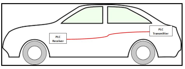
As a dependable alternative networking medium, this studyoffersanin-vehiclepowerlinecommunication(PLC) system that allows in-vehicle communication for the transmissionofvehiclemessagesfromvehiclecontrolunit to body control module. The Power Line Communication for vehicle system uses an existing 12-volt battery power wires as the communication media, which eliminates the need for an additional signal wires for traditional invehicle signal transmission. in order to meet the goal of vehicle message transmission for driving safety we can utilize this technology. We can achieve the reduction of numberofwiringharnessfromvehiclejunctionboxtorear side features (Stop light, reverse light, number plate light, demister, rear wiper, rear indicators) with the safety features like short circuit protection, fault protection and feedbacktovehiclecontrolunit.
In existing wiring harness technology, for every BCM function and sensor require power input from battery. Sensors are sending data to vehicle control unit through separate wire. Each sensor and switch is interfaced with vehicle control unit to communicate analog data or/and digital data. Digital data can be On-Off signal generated from limit switches & push buttons. This sensor information is gathered to Power Line Communication transmitter.Transmitterwillsendgatheredinformationon power wire coming from battery and receiver will catch
this data over same power wire and takes appropriet decisionor/anddataloggingfunction.
Thispowerlinecommunicationwill reducethenumber of wires, complexity of wiring harness design, weight of harness and production of wiring harness. Hence cost will reduce.
2: LITRATURE REVIEW
M. Olivas Carrion, M. Liénard and P. Degauque –
“Communication over Vehicular DC Lines: Propagation Channel Characteristics” [1]
This paper investigates the propagation channel characteristics of a power line communication inside a vehicle. Transfer functions have been measured between various points of the DC network in a frequency range extending from 500 kHz up to 70 MHz to deduce the statistical behavior of the path loss, delay spread and coherence bandwidth. The results are compared to those obtained with a deterministic propagation model, simulating the entire cable harness. In a vehicle, data transmission between electronic equipment is now achieved owing to a lot of dedicated cables, Despite the additional cost, an increase of the total weight and the possiblelackofreliabilityofthemultipleconnections
S. Barmada, M. Raugi, M. Tucci, T. Zheng - “Power Line Communication in a Full Electric Vehicle: Measurements, Modelling and Analysis”.[2]
The technological implementation is nowadays done by using different data bus (Local Interconnect Network, Controller Area Network, Media Oriented Systems Transport, FlexRay), depending on the required communication speed and reliability. A modern vehicle of average dimension is characterized by a communication gridofseveralkm,withaconstantlyincreasingnumberof connection points (more than 200 nowadays). The weight of the wiring harness is second only compared to the engine – gearbox weight. It is not difficult to understand that the complexity of this structure will soon become an issue difficult to manage, also from the diagnostic and maintenance point of view. For this reason the use of power lines to transmit data could reduce this problem, since it would remove part of the cables (or all of them in the best case) for command and control with enormous advantagesintermsofweight,spaceandcost.

Sheng-Xiu Lin, Yuan-Hua Zhang, Chao-Tang Yu, WeiWen Hu, Liang-Bi Chen, and Wan-Jung Chang – “A DC Power-Line Communication based In-Vehicle Safety Aided System for Rear Vehicles Road Safety” [3]
This paper proposes an in-vehicle safety aided system, whichadoptsDCpower-linecommunication(DCPLC)asa main transmission channel. The proposed system is composedofa voice-to-text (VTT)module,two embedded computermodules,twoDCPLCtransceivermodules,atext and video message display module, and a distance measurement module. Moreover, the proposed system is successfully installed and tested in a real vehicle. The experimentalresultsshowedthattheproposedsystemcan have a data of distance to the adjacent rear vehicle, and displayfrontviewvideowithalertingmessagesfordrivers of rear vehicles. As a result, the proposed system can be applied to alert the drivers of rear vehicles to achieve the purpose of road safety. there is no direct communication scheme among two vehicles. Occasionally, a vehicle driver needs to alert the front vehicle driver though flashing headlightorpressingthehorn.However,thevehicledriver couldnotconveyanymessagestothevehiclebehindhim.
Gang-Neng Sung1, Chun-Ming Huang, and Chua-Chin Wang – “A PLC Transceiver Design of In-Vehicle Power Line in Flex Ray-based Automotive Communication Systems” [4]
This paper presents a power line communication (PLC) transceiver designofin-vehiclepowerlinecompliant with FlexRaycommunicationsystems.FlexRay-basedin-vehicle power line communication provides a solution for high reliability without increasing weight, volume and cost of the wiring harnesses. A 16-QAM (Quadrature amplitude modulation) scheme is utilized in the transceiver design. TheFlexRaystandardisdesignedforanin-carnetwork. It will not replace the existing network, but it can combine and integrate with existing systems, including CAN (Controller Area Network), LIN (Local Interconnection Network), MOST (Media Oriented System Transport) [1] andJ1850protocoletc.FlexRayrequires10Mbpsdatarate in either one of the two channel of an ECU. If a single channel is used alone, the speed of the total data rate will reach 20 Mbps. Fig. 1 shows the feature of FlexRay when used(X-by-wire).
3. PROBLEM STATEMENT
Thetraditionalwireharnessingtakesupalotofspaceand weight even in compact cars. The wiring harness is one of three heaviest subsystems in many vehicles, as much as 150 lbs in highly contented vehicles. It’s very typical for theaveragevehicletohave100–120lbsofwireharnessin thevehicle.Today’scarscontainsome1,500–2000copper wires totaling over kilometers in length. The most critical factors for vehicle manufacturing is weight of vehicle and manufacturingprocesstime.
Whiletheautomotiveindustryworkstolowerthe weightandaddelectronicdevices,thosecircuitsalsomust bereliableenoughtoensuresafetyofcriticalsystems.
4. SCOPE OF THE PROJECT:
Power line communication (PLC) system for vehicle that allows in-vehicle communication for the transmission of sensor messages/data and. Now a day’s more sensors are inserted in vehicles as functional safety features PLC will offerslowcost,lesscomplexityofwirenetworking.
This Power line communication will add advantage of lower cost of wires, wiring manufacturing process and henceincreaseproductivity.
Thistechnologyisveryusefulforfutureelectricvehicles(E –Vehicles)becausetoincreasethedistancecoverageofE–vehicle manufacturers are more focusing on reducing the weightofvehiclesothatvehiclecancovermoredistancein singlechargeofbattery.
5. BLOCK DIAGRAM OF POWER LINE COMMUNICATION
The power line communication block diagram comprises withpowerlinetransmitter,powerlinereceiver.
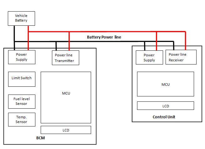
Battery: Vehiclebatteryisthepowersupplyforallvehicle electronics.
Power supply: power supply is the voltage converter to convertbatteryvoltageto5Voutputfordigitalelectronics,
Temperature sensor, Fuel level sensor, Limit switch: Thesearesensorsinterfacestotransmitter.
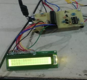
LCD: LCDdisplaysthetransmittedandreceiveddata form transmitterandreceiverrespectively.
Transmitter MCU: Microcontroller unit is to reading the sensors data in analog form and converting in to digital through ADC channel. This converted data is sent to transmitter.
Power Line Transmitter: Power line transmitter will send the data received from controller UART over power wire,intheformofhighfrequencypulses.
Power Line Receiver: Power line receiver will filter out datapulsesfrompowerwire.Filtereddatapulsesaresent toreceiverMCUfordisplayingonLCD.
Receiver MCU: Receiver MCU receives UART pulses from powerlinereceiveranditwilldisplayoverLCD.
6 OBJECTIVE
1. Design the UART transmitter and receiver for simple communication with two microcontroller system.
2. Interfacing resistive level sensor (potentiometer) and two switches as input to the transmitter controller.
3. InterfacingLCDfortransmittercontrollertoshow thetransmittingdata.
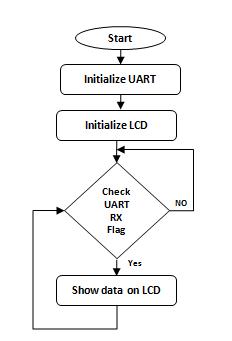
4. Interfacing filtered received data with receiver microcontroller pin and interfacing LCD for showing received data from transmitter to show thecompletecommunicationoverpowerwire.
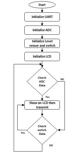
7. FLOW CHART
8. SYSTEM WORKING
1. Power line transmitter: Power line transmitter (Vehicle BCM) comprises with power supply section, sensors like level sensor, switch type sensors, LCD display, and 8 bit microcontrollerunit
2. Power line transmitter is getting power supply from vehicle battery. Same battery and battery cables are providedtoreceiversectionofproject.
3.PowersupplyofBCMisproviding5Vtomicrocontroller, sensors and other devices on transmitter board. The transmitterBCMislocatedonrearsideofvehicle.
4.Onrearsideofvehiclethrearemanysensorstosendthe data to control unit with analog communication happning withsinglewire.
5. But in this technique all sensors are connected with BCM, receiver board microcontroller will collect the data fromsensorsandtransmittocontrolunit.
International Research Journal of Engineering and Technology (IRJET) e-ISSN: 2395-0056
Volume: 10 Issue: 02 | Feb 2023 www.irjet.net p-ISSN: 2395-0072
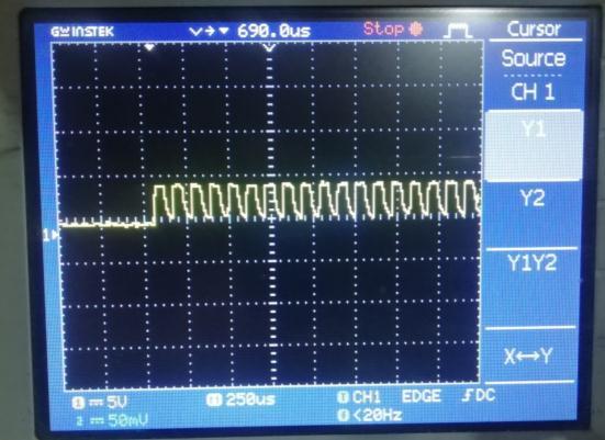
6. Transmitter will send the signal over the power supply wirewithhighfrequency.Now12VDCandcommunication signal is travels on same wire. We can see in oscilloscope imagesinthispaper.
7. Receiver board is getting power supply from same wire for transmitter. Communication signal is superimposed over12VDCthatisfilteredbypowerlinereceiver.
8. Power line receiver will filter out the communication signal form 12VDC. This filtered signal is buffered and strengthensfordrivingRXpinofreceiverMCU.
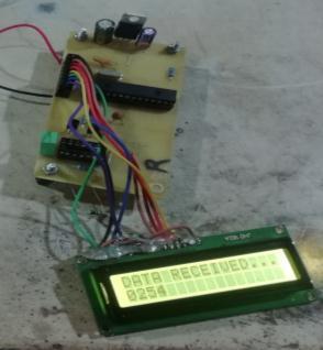
9. Receiver MCU will get the transmitted data and data is displayedonLCDtheresultwewillseeinresultsectionof thispaper.
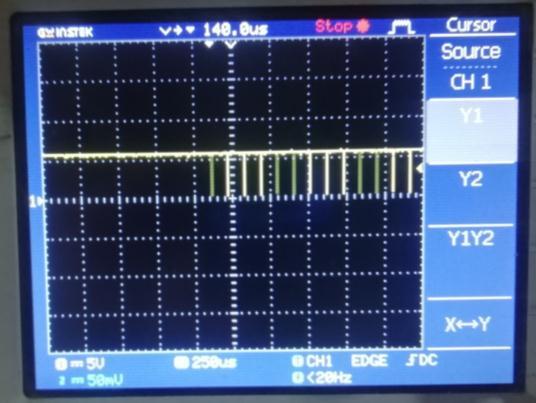
Infigure7wecanseethepulsesfromTXpinoftransmitter board controller. Amplitude is 5V that is microcontroller outputherepulsesareverycleananddistortionfree
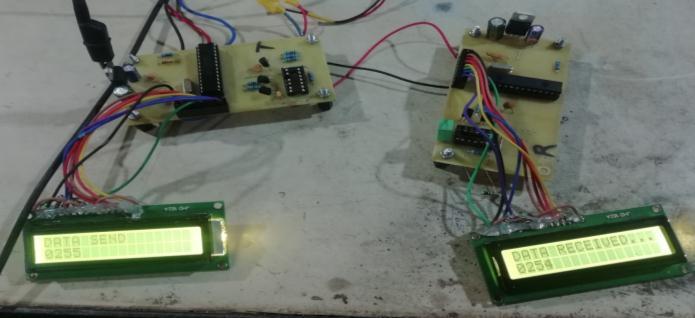
POWER LINE PROJECT SETUP:
In project setup there is two PCBA boards, power line transmitter and power line receiver board. Both boards are interfaced with batter cables only. Thease battery power cable is responsible for communication between them. Transmitted ADC data count is shown over transmitter as well receiver display. The tolerance of receiveddatacountis±2counts.
10. Power Line Transmitter result waveform
In Figure 8 we can clearly see the signal coupled over 12VDC bus. 5V pulses are superimposed over 12VDC voltage.
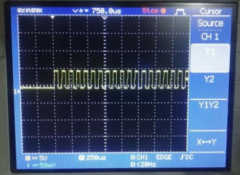
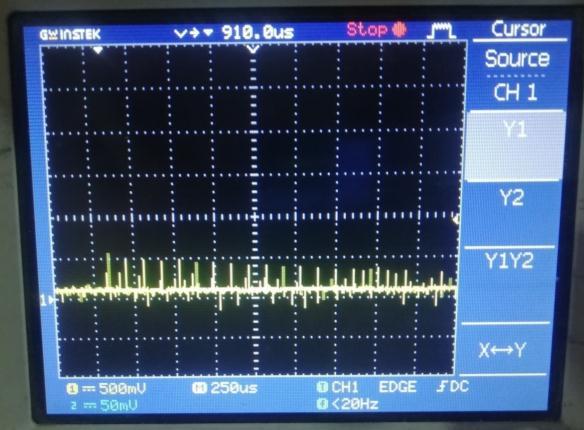
13 Power Line Receiver result waveform
The pulses received form transmitter are so noisy and having distortions. So this received distorted signal pulses are fed to buffer filter which complements the received pulsesforRXpinof receivercontrollerwewill seeinnext result.
Thecaptured pulsesareshown infigure 11are the pulses at RX pin of receiver microcontroller. These are narrowed becauseofdistortionandfastdischargingcharacteristicof capacitor these pulses are capable to drive the TX pin of controllertodecodethemessagesentbytransmitter.
We can enhance this system for real time high speed data in MbPS rating to achive the video streaming from rear parking camera. This Power line communication will add advantage of lower cost of wires, wiring manufacturing processandhenceincreaseproductivity.
Thistechnologyisveryusefulforfutureelectricvehiclesto reducing the weight of vehicle so that vehicle can cover moredistanceinsinglechargeofbattery.
13. PROPOSED WORK OUTCOMES
The advantage of the Power line communication is to transmit and receive communication signal over 12DC power supply wire. Communication over power supply wire will allow to reduce the number of wire require to send sensor data from rear side of vehicle. Reduction in numberofwirewillleadtoreduceweight,complexityand costofwiringharnessinvehicle.
Acknowledgement
I have great pleasure and sense of satisfaction in presenting this dissertation report on “Power Line Communication for Communication” as a part of curriculumofM.Techelectronicsandtelecommunication.I am very fortunate by people with vast experience in the irrespectivefieldwork.
I am greatly indebted my guide and advisor Prof.WagdarikarA.UIcouldnothaverealizedmypotential without his invaluable guidance, consistent encouragement, and emphasis on quality of the presentationandforsharinghisprofoundknowledge.Iam verythankfultohimforallthetimetodiscussionwithme, aswellasguidingmeinrightdirection.
REFERENCES:
11. CONCLUSION
We have developed a 12V DC-based PLC system for in-car communication in order to make a reliable alternative networking method for vehicle in this study. The fundamental aim of this work for an application is to give vehicle message delivery via an PLC system for driving safety feature. Electrical wiring harness is used in power line communications technology to transmit data at fast speeds. It can provide the data rate, performance, flexibility, dependability, and cost-effectiveness required forvehiclenetworking.
12. FUTURE WORK
Power line communication (PLC) system for vehicle that allows in-vehicle communication for sensor messages/data. The system is providing speed of data for messages and small data packets of data which can transmitthesensordatalikedigitalcountoverpowerline.
[1] A Sudhakar, Shyammohan S Palli "Circuits and NetworksAnalysisandSynthesis,"FourthEdition
[2] G.-N. Sung, C.-M. Huang, and C.-C. Wang, "A PLC transceiverdesignofin-vehiclepowerlineinflexray-based automotive communication systems," IEEE International Conference on Consumer Electronics (ICCE'12), pp. 309310,2012.
[3] M. Wilson, H. Ferrira, and R. Heymann, "Markov modelling of invehicle power line communication," AFRICON'13Proceedings,pp.1-6,2013.
[4] R. P. Antonioli, M. Roff, Z. Sheng, J. Liu, and V. C.M. Leung, "A realtime MAC protocol for in-vehicle power line communications based on homeplug GP," IEEE 81st VehicularTechnologyConference(VTCSpring'15),pp.1-5, 2015.
[5]L.-B.Chen,H.-Y.Li,W.-J.Chang,J.-J.Tang,andK.S.-M.Li, "An intelligent vehicular telematics platform for vehicle
driving,"inL.-B.Chen,H.-Y.Li,W.-J.Chang,J.-J.Tang,andK. S.-M. Li, "An intelligent vehicular telematics platform for vehicle driving," in An SDN-MQTT Based Communication SystemforBattlefieldUAVSwarms[J]
[6] Xiong F, Li A, Wang H, et al. IEEE Communication Magazine, vol. 57, no. 8, pp. 41-47, 2019.Optimal LinkDisjoint Node-"Somewhat Disjoint" Paths [2] YALLOUG J, ROTTENSTREICHO,BABARCZIP,etal.
[C]/ IEEE International Conference on Network Protocols Proceedings.1–10,Singapore,2016.
[7] H J GENE, X G SHI, Z L WANG, et al. Efficient LFA implementation method[J]. Journal of Software, 29(12), 3904-3920, 2018. Full Protection Made Easy: The dispath IP Fast Reroute Scheme [J]. ANTONAKOPOULOS S, I3EJERANO Y, KOPPOL P. IEEE/ACM Transactions on Networking,vol.23,no.4,pp.1229-1242,2015.
[8] Failure Inference for Shortening Traffic Detours[C]/ Proceedings of the International Symposium on Quality Service. XU A, BI J, ZHANG B. Failure Inference for Shortening Traffic Detours[C]/ Proceedings of the International SymposiumonQuality Service.1-10, Beijing, China,2016.
[9] N. Taherinejad, R. Rosales, L. Lampe, and S. Mirabbasi, “Channelcharacterizationforpowerlinecommunicationin a hybrid electric vehicle,” in Proc. IEEE International Symposium on Power Line Communications and Its Applications(ISPLC),March2012,pp.328
333.
[10] M. Bogdanovic, “Computer based simulation model realization of odfdm communication over power lines,” in Proc.TelecommunicationsForum(TELFOR),2012.