Semi-Automatic Engine Valve Cleaning Machine Using Cam and Follower Mechanism
1,2,3,4Students, Department of mechanical Engineering
5Professor, Department of mechanical Engineering
Pimpri Chinchwad College of Engineering and Research, Ravet, Pune, Maharashtra, India

Abstract - A significant portion of the automotive industry and a significant source of revenue for businesses is automotive maintenance.Thevalvelappingmethodcoveredin this thesis is carried out duringtheinternalcombustionengine maintenance, which is currently regarded as a crucial component of automobile maintenance. The existing techniques for valve lapping employed by the majority of auto repair shops are inefficient and take up a lot of time. By reducing the need for human intervention, the "Valve lapping Machine for Internal Combustion Engines" machine is intended to solve these issues
As the abrasive goes back and forth between the two surfaces and removes material from both, minute conchoidal fractures are created. According to observations, if valves are not lapped, some of the energy from the consumed gases will be wasted, which will result in the engine not having adequate power. Therefore, since this task is semi-automatic, it is not necessary for the worker to have previous knowledge in order to use this equipment to clean four-stroke valves. The major objective of this project is to develop a machine that is more effective and efficient than currently utilised techniques for valve lapping while also lowering labour costs by minimising the need for human intervention.
Key Words: Valvelapping;Enginevalves;Cylinderhead
1. INTRODUCTION
Inordertopreventcompressionleaksfromthecombustion chamber through the seating from the process of valve lappinginaninternalcombustionenginecylinderheadand topreventair/fuel/airmixtureleakingintothecombustion chamberthroughtheseating,agoodseatbetweenthevalve seating area of an engine valve and the valve seat area of cylinder head is desired. The internal combustion engine works by establishing a specific compression ratio, which variesfromenginetoengine,andcombustingacompressed air-fuelmixturetoapredeterminedvolume.Andifthefuelairmixtureseepsthroughtheseats,thecombustionprocess won'toccurbecausethefuel-airmixturevolumewillchange.
1.1 Lapping process
Wemustoccasionallylookdirectlyatthevalveseatarea when the valve is being lapped. It's the typical method of determiningifthevalveseatissoundorwhethermorevalve
polishing isrequired.A lappedand an unlapped valveare seeninFigure2.Themostpopularmethodforwatchinghow valves are sitting after valve lapping is one that involves gasoline. After completing the valve job, the mechanic or technicianplacestheprecisevalveinthepreciselocationin the cylinder head and adds fuel to the valve stem that he mustwatch.Thevalve'sseatingareaisthenreachedbythis spilledgasoline.
1.2 Engine valves
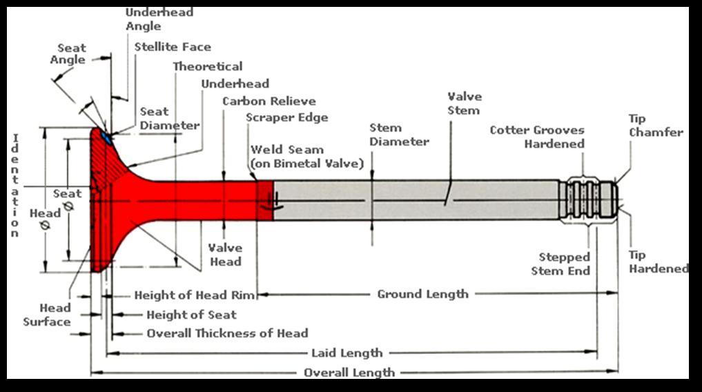
Exhaust and intake valves are the two different types of enginevalves.Inacylinderhead,thesevalvesmightbeeasily recognized.Exhaustvalvesareoftensmallerthaninletvalves. Although there may be multiple inlet valves and exhaust valves for a single cylinder. Both inlet valves and exhaust valves come in a variety of designs. Poppet valves are the typeofvalvethatareusedthemostfrequently.Next,certain turbocharged engines include sodium valves. And under variouscircumstances,maskvalves,mushroomvalves,and tulipvalvescouldbeseen.Avalveisillustratedingreatdetail inthefollowingfigure.
Fig-1: ValveTerminology
1.3 Lapping compound
Beforebeginning,alappingcompoundisputtothevalve seat.Thecylinderblock'svalveandvalveseataresmoothed out by lap compound wear, which also improves the seat. Twodifferenttypesofcompoundsareoftenofferedinthe top and bottom ends of a lapping compound tube
individually.thetwocategoriesdenotedascoarseandfine. Bylookingatthevalveseat,thetechniciandetermineswhich sortofcompoundshouldbeused.Coarsecompoundisused if the valve seat has jagged edges. Otherwise, a smooth surfaceisachievedwithafinecompound.
1.4 Cylinder head
The inlet and exhaust valves and their ports are located in the cylinder head for the intake of the air/fuel combination and the exhaust of the combustion products. Thecylinderheadisthecastingthatsealsthecombustion endofthecylinderblock.Ifanoverheadcamshaftispresent, thecylinderheadalsomakesrockerarmsandvalvesprings possible
2. Plan of Work
1)Duetotheproblemofafriend'scarbreakdown, Wecame acrosstheprocesscalledasthevalvelapping.
2)Duringtheservicingofcarweidentifiedtheproblemthat valve lapping process is very time consuming, So we brainstormedvariousideasaboutdevelopingamachinethat willmakethisprocesstimeefficientsowedecidedtomake thisourBEProject.
3) We started our work with searching various research papers from various articles and published journals and identifiedthegap.
4) After research and identification of gap we worked on various mechanism and found that cam and follower mechanismissuitableforourprojectandwefinalized
5)Nextstepwasdesigningtherough2Dmodel.
6)Calculationofstandardcomponentsweredoneandafter that 3D model of our machine was completed using the CATIAV5Software.
7) After that Analysis of machine components was done usingANSYSSoftwareandparameterssuchasstrengthof componentsandstressonitiscalculated.
8)Standardcomponentsaccordingtomachinerequirements wereselectedandmanufacturingofmachinewascompleted.
9)FinallythetestingofMachinewascarriedouteffectively.
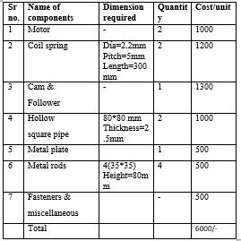
3. Bill of Materials
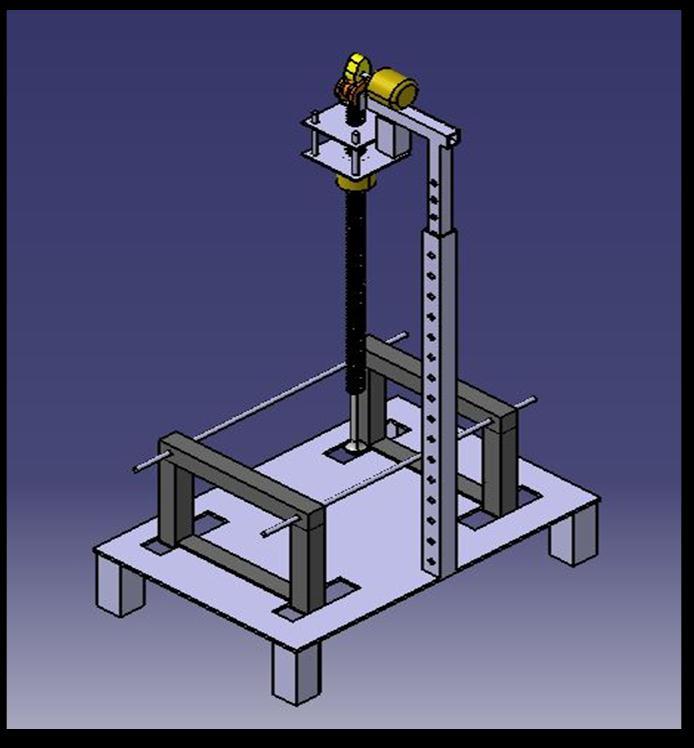
4. CAD DESIGN
Usingcomputersystems(orworkstations)tohelpwiththe creation, revision, analysis, or optimization of a design is known as computer-aided design (CAD). CAD software is usedtodevelopdatabasesformanufacturing,boostdesigner efficiency, enhance design quality, and improve communicationsthroughdocumentation.Electronicfilesfor printing,machining,orothermanufacturingprocessesare frequentlytheCADoutput.AnotherwordusedisCADD
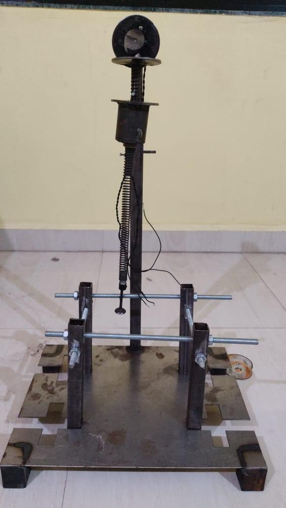
5.WORKINGOf SEMI AUTOMATIC VALVE CLEANING MACHINE:
Thefirststepisthat,wearegoingtofixthecylinderheadon the base plate with the help of frame consisting of Lead screws and make the adjustments according to cylinder head.Theheightadjustmentoftelescopictubeisdoneusing nutandboltbymatchingthetwodrilledholesontheinner andoutertubes,accordingtocylinderhead.
TheLappingstickisattachedtohighstiffnessspringusing washer.Thevalvewillbeattachedtothelappingstickwith helpofsuctioncupprovidedontheotherendofthestick.
Afterthatthecompoundpastewillbeappliedonthevalve seatandthevalvewillbeinsertedintheenginehead.Hard abrasiveparticlesarecombinedwithanappropriatebaseto create lap paste. The basis might be a water-soluble lubricantoranoil-basedsubstancelikegrease.Commonly usedcompoundpastes/lappingpowderaresiliconcarbide, aluminiumoxide,boroncarbide,diamondpowders,etc.
Thebatteryisusedtoprovidethepowerto2motors[motor1(reciprocatingmovementofcamandfollower)andmotor-2 (rotationofvalvespecimeninclockwiseandanti-clockwise direction)
FurthertheinputwillbegiventotheArduinoUNOwhichis connectedtopowerbankforcontrollingthemotor2which isgoingtorotatevalvespecimeninthecylinderheadinsuch a way that good seat will be obtained between valve and cylinderheadandhence,thecleaningofcarbondepositedon thevalveseattakesplace.
6.ANALYSIS OF MACHINE USINGANSYS SOFTWARE.
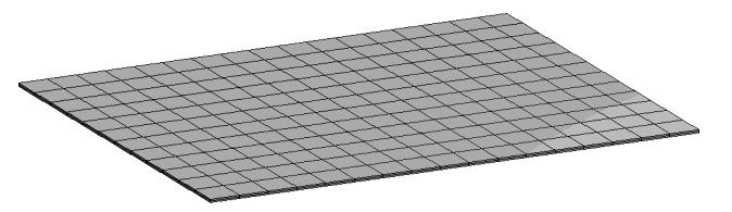
6.1 Mesh
An intelligent, automated, high-performance generalpurpose product is ANSYS Meshing. For precise, effective Multiphysicssolutions,itgeneratesthebestmesh.Asingle mouse click can create a mesh for every component of a modelthatissuitableforacertainstudy.WithintheANSYS Workbenchenvironment,ANSYSMeshingisautomatically integratedwitheachsolver.
6.2 Boundary Condition:
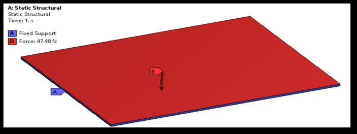
Anrelatedloadoraknownvalueforadisplacementareset asaboundaryconditionforthemodel.Youcanonlysetthe loadordisplacementforagivennode;youcannotsetboth. Force,pressure,andtemperaturearethethreebasicloading types that are offered in FEA. These may be utilised with respecttopoints,surfaces,edges,nodes,andcomponents,as wellasbeingremotelyoffsetfromafeature.
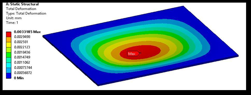
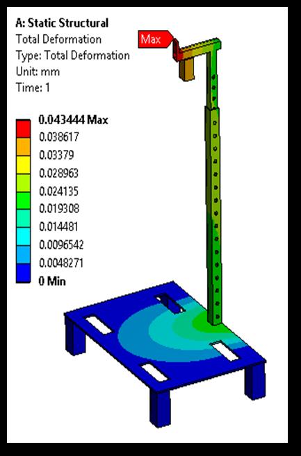
6.3 Total Deformation:
Regardless of the programme being utilised, the phrases
"totaldeformation"and"directeddeformation"aregeneral conceptsinfiniteelementmethods.Thedisplacementofthe systeminacertainaxisoruser-defineddirectionisreferred to as directional deformation. The vector sum of each system's directional displacements represents the total deformation.
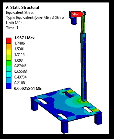
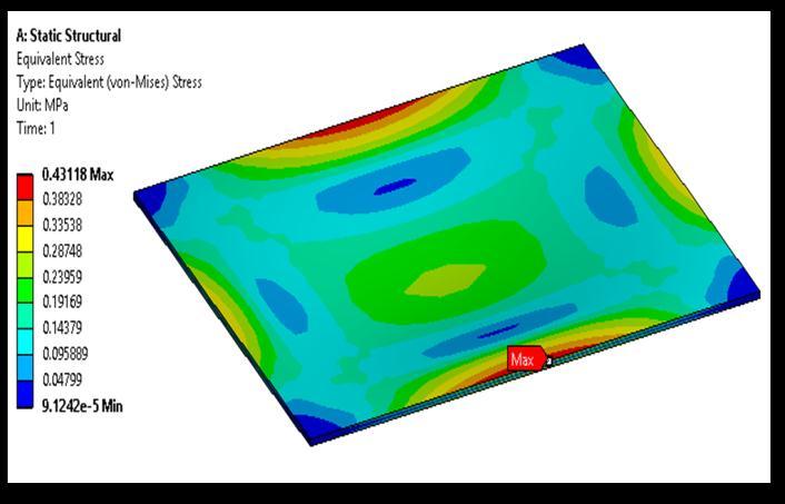
6.4: Equivalent Stress
Theconceptofequivalentstress,alsoknownasvonMises stress, is frequently applied in design work because it enables the representation of any arbitrary threedimensionalstressconditionasasinglepositivestressvalue. Themaximumequivalentstressfailuretheory,whichisused toforecastyieldinginaductilematerial,includesequivalent stress.
1. From the analysis results, it is clear that the maximum stressinducedislessthanthatoftheyieldstrength.So,the designissafe.
2. This machine is effective & efficient than the available methods.
3. Time taken by using the machine to clean the valve is considerablylessascomparedtothetraditionalmethodby almost12mins.
9. Concluding Remarks:
1)Henceconcludedthattheconventionalmethodsusedfor cleaningthevalvesismoretediousandtimeconsuming.Due to the development of automated mechanism the job got easierandthecycletimeisalsoreduced.
2)Valvelappingmechanismwillbeimplementedreplacing manuallabour.
3)Dueto developmentofsemi-automatedmechanism for valve lapping the mechanical effort required is being also reduced.
4)Valvelappingmechanismwillbedesignedasanassembly ofseveralpartseasinganymaintenancetothemachine
10. References:
[1] Avinash Kumar Agrawal_1, Shrawan Kumar Singh2, ShailendraSinha1AndMritunjayKumarShukla1,“Effect of EGR on the exhaust gas temperature and exhaust opacity in compression ignition engines”, Vol.29,Part3,pp.275–284June2004.
[2] S. M. Fulmali, R.V. Chadge “Need of valve lapping machine for valve component”, International Journal of Modern Engineering Research IJMER, Vol. 2, Issue. 6, pp4609-4612,Nov.-Dec.2012
[3]Prof.D.Kotkar,PankajPujari,ChetanArote,TusharKale, KiranKawale, “Design and Development of Valve Lapping Machine”,InternationalJournalofEngineeringResearch& Technology(IJERT),Vol.8Issue06,June-2019.
[4] Ayodhya Abeysekara, “Valve Lapping Machine for Internal Combustion Engines” International Journal of EngineeringResearch&Technology(IJERT),Vol.3Issue06, Feb2015.
[5] Eraldo Jannone da Silva, Eduardo Carlos Bianchi, João FernandoGomesdeOliveira,PauloRobertodeAguiar, “The Inlet Engine Valves Grinding Using Different Types of Cutting Fluids and Grinding Wheels”,MaterialsResearch, Vol.5,No.2,187-194,2002.
[6] M. R. Pratheesh Kumaret, M.R. Pratheesh Kumar, B.S Arun, R. Aravind Babu, “Optimization of Process Parameters in Lapping of Stainless Steel”,International JournalofEngineeringResearch&Technology(IJERT),2013.
[7]S.M.Fulmali,R.B.Chadge,“Need ofLappingMachinefor Valve Component: A Case Study”,InternationalJournalof ModernEngineeringResearch(IJMER),2012.
[8]OwatSunanta,“Flat surface lapping: processmodeling in an intelligent, Environment”,UniversityofPittsburgh, 2002.
[9] G.D. Roy, S.M.Frolov, A.A. Borisov, D.W.Netzer, “Pulse detonation propulsion: challenges, current status, and future perspective” Prog. Energy Combust. Sci. 30 (6) 545e672,2004.
10]P.Dominique,P.Alban,S.Laurent,“Performance of a Valveless Air-Breathing Pulse Detonation Engine” , AmericanInstituteofAeronautics&Astronautics,pp.20043749,2004.
[11] Xiobin le and M.L. Peterson, Dept of Mechanical Engineering,ColoradoStateUniversity, “Material removal rate in flat lapping”, Journal of Manufacturing Systems”.
[12] C.J. Evans and E. Paul, Zygo Corporation, Middlefield, USA, “Material Removal Mechanisms in Lapping and Polishing”, CIRP Annals -Manufacturing Technology”.
[13] Lalit Suhas Deshpande, Shivkumar Raman, Owat Sunanta, University of Oklahoma, United States, “Observations in flat lapping of stainless steel and bronze”, InternationaljournalofScienceandTechnologyof friction,lubricationandwear.
[14] H.Y. Tam, H.Y. Tam, Y.W. Wang, Department of manufacturing engineering and engineering management, CityuniversityofHongKong, “Removal rate and surface roughness in the lapping and polishing of RB-Sic optical components”, JournalofMaterialsProcessingTechnology.