Wireless Smart Traffic Control System based on Vehicle density in Traffic Lane and Emergency Vehicle detection

1B.Tech. Student, Dept. of Computer Science and Engineering, D. Y. Patil College of Engineering and Technology (An Autonomous Institute), Kolhapur, Maharashtra, India ***
Abstract - This paper's primary objective is to automatically change the move forward time between traffic light systems in response to the volume of traffic in each lane. In today's society, most cities face a serious problem with traffic congestion. Ineffective if one lane is open for a longer period of time than the others are the fixed time-based systems used by modern traffic signaling systems. Such system wastes a lot of labor hours and will lower individual productivity. Here, we suggest a system in which the length of the green and red signals depends on the volume of traffic in the area at the time. As opposed to fixed time-based systems, sometimes there is more traffic congestion on one side of the lane and a longer green signal is required. In order to best address this issue, we must create an automated traffic control system. This can be done using IR (Infrared sensors). The microcontroller (ESP8266), after determining the density, prioritizes the lane with the green signal's luminous period. Lanes with priority vehicles, such as ambulances, are given the highest priority. After some time, even though the lane has a lower vehicle density, a green signal is given to it to avoid starvation. The microcontroller will use the data from the sensors that are installed on either side of the road at a specific distance and will detect the number of vehicles passing that lane to determine which lane is to be freed. Further sections have elaborated the procedure of this structure.
Key Words: IoT, Wireless, IR Sensor, Traffic light system, LCD, ESP8266
1. INTRODUCTION
ThemainreasonofIndia'strafficcongestionisits enormous population. Because of the rapid increase in populationandthedailycapitauseofautomobiles,thereis one fatality on the road every four minutes, which will increasethedemandforfuel[1–5].Themassiveincreasein vehiclesandlongerintervalsbetweentrafficlightsystems makecontrollingtrafficcongestionanotherfactasignificant problem. Individual productivity is decreased, and a significantamountofworktimeislostinthesesystems[8] .Inefficient infrastructure, massive vehicle populations, impatient drivers, illogical distribution, and population growthareforemostreasonsoftrafficcrowding.Aslongas theenginesarerunning,whichisthecaseinthemajorityof cases,thepollutionlevelquicklyrises[7–11].Additionally,a tremendousamountofnaturalresources,namelygasoline
and diesel, are drained away without producing anything. Therefore, in this area of traffic signaling system, newer schemes must be implemented using sensor-based automationtechniqueinordertosolvetheseproblems.
Insection2ofthisarticle,acompleteexplanationis provided.Insection3,thesuggestedsystem'sblockdiagram is explained. In section 4, the results analysis is described andlastlyconclusion.
2. EXISTING SYSTEM
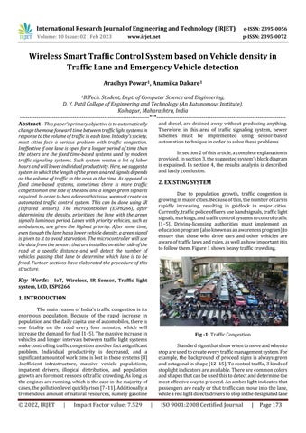
Due to population growth, traffic congestion is growinginmajorcities.Becauseofthis,thenumberofcarsis rapidly increasing, resulting in gridlock in major cities. Currently,trafficpoliceofficersusehandsignals,trafficlight signals,markings,andtrafficcontrolsystemstocontroltraffic [1–5]. Driving-licensing authorities must implement an educationprogram(alsoknownasanawarenessprogram)to ensure that those who drive cars and other vehicles are awareoftrafficlawsandrules,aswellashowimportantitis tofollowthem.Figure1showsheavytrafficcrowding.
Congestion
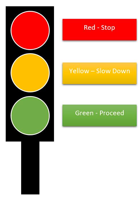
Standardsignsthatshowwhentomoveandwhento stopareusedtocreateeverytrafficmanagementsystem.For example, the background ofproceed signs isalways green andoctagonalinshape[12–15].Tocontroltraffic,3kindsof stoplightindicatorsareavailable.Therearecommoncolors andshapesthatcanbeusedthistodetectanddeterminethe mosteffectivewaytoproceed.Anamberlightindicatesthat passengersarereadyorthattrafficcanmoveintothelane, whilearedlightdirectsdriverstostopinthedesignatedlane
atthedesignatedtime.Vehiclesmustturnonagreenlampto leavethelane.Trafficlightsarecurrentlysetupwithfixed timedelaysandswitchfromonesignaltoanotheraccording toapredeterminedcycle[8-15].
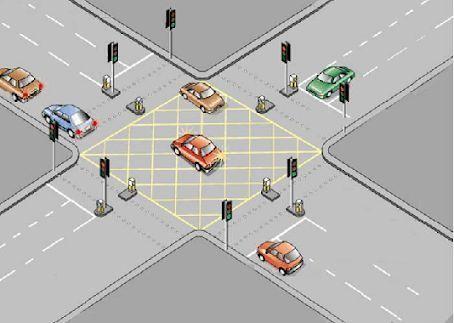
open.Anynodecanbeconnectedtobyemergencyvehicles, anddependingonwhichnodeisconnected,thesignalforthat lane is changed to green. Every time the signal changes, it glowsonthetrafficlightsystemandappearsonanLCD.Each lanewithlighttrafficisalsogivenagreensignalinorderto reducetheamountoftimedriversmustwaitforthelanewith light traffic. The lanes with emergency vehicles are given priorityhere,followedbythelaneswithmorevehicles,and thelaneswithfewervehiclesaregivenleastpriority.Each node is connected to the IR sensor and traffic light. The MasternodehasanLCDscreeninadditionthat showsthe statusofallthesignals.Thesectionsbelowdisplaytheblock diagramoftheproposedsystem.
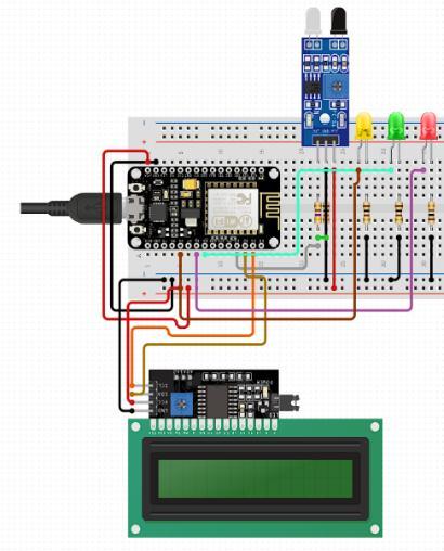
Trafficlights,IRsensors,NodeMCUs(ESP8266),and anLCDmakeuptheproposedsystem'sblockdiagraminthe Figure 3. The proposed system works because of these components.Thefunctioningoftheseelementsisdescribed below.
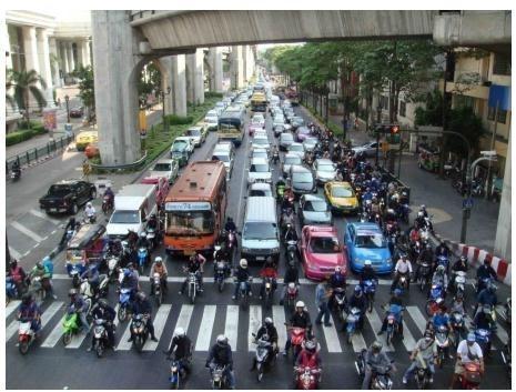
Toguaranteethesafestpossiblemovementofboth trafficandpedestrians,normaltrafficlightoperation(figure 2)requiresasmallamountofcoordinationandcontrol[17–20].Vehiclesareunabletomoveasquicklyastheyshould whenthereistrafficcongestionbecausetherearediverse, while the approval period is short. However, there aren't many vehicles using the sublane, and the approval period rangeisextensive.Thiscausingwastefulandinappropriate congestioninoneofthelaneswhiletheothersarestillclear [16].WiththeuseofSensors,trafficlightsystemshavebeen putinplaceadjustingthelagtimeaccordingonthequantity of traffic in a specific route [19]. The sensors, that detect trafficsystemandcommunicatewiththemicrocontroller,are positioned at specific intervals on each side of the road. If there is possible lane congestion, the sensors will communicate this information to the microcontroller [16–21].Themicrocontrollerdetermineswhentoopenthelane basedonthedatafromthesensors.
3. PROPOSED SYSTEM
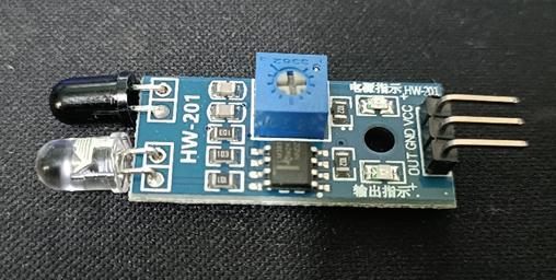
Thismodelisbasedontheideathatthevolumeof trafficthatpassesthroughaspecificstretchofroaddictates howlongtrafficsignalsaredelayed.Here,insteadofusinga trafficlightsystemwithafixedtimedelay,aninfraredsensor willbeplacedataspecificdistancefromeachsideoftheroad. TheIRsensor'srangeisapproximately10meters.ItisanIR transceiver,whichcombinesanIRtransmitterandreceiver. On the sides of the street, there are numerous sensors installed.AspecificdistanceapartIRtransmitterandreceiver mounts will be placed on either side of each lane. When a passing vehicle is identified, these IR sensors send the informationtotheSlavenodestowhichtheyareconnected. TheMasternodereceivesthisinformation.TheMasternode willdeterminethenumberofvehiclesthatarewaitinginthe lane using the data, and it will then signal that the lane is
The equipment for smart traffic management systemneeds5Vinrelationtoground,thatpowersupplyis used.Inthissituation,thatpowersupplyisutilizedinthis instance. TTL logic value of the circuit is 0–5V.220 v AC supply is abruptly resigned to 9 v AC using a 0 v to 9 v transformer.Aseriesconverteralsochanges9VACto9VDC. Then, to obtain 5V, it is further filtered using a 1000 uF capacitorandcontrolledbya7805.Itisnowtimetoturnon the power supply, LCD, microcontroller, and traffic light system. As soon as each node receives power, the slave nodes connect to the master node, and using the "STATIONAP"configuration,allnodescreateanaccesspoint with the physical mode set to 802.11b. The longer-range IEEE 802.11b protocol is used here. The IR sensors then begintoanalyzeamountofautomobileswithineverytrack. Additionally,masternodereceivessuchdataand,following
decision-making, sends a signal to every node. The emergencyvehicleshaveanESP-01nodethatcanconnectto anyofthenodesandthenaskforagreensignal.Basedon thenodetowhicharescueautomobilessentrequest,forthat lane, green light is given. The ESP-01 is present in the emergency vehicle. Figure 4 shows the ESP-01 ESP8266Module.Microcontrollerscanconnecttowireless networksusingtheESP8266ESP-01Wi-Fimodule.Withthis module, you can control inputs and outputs without necessarilyneedingamicrocontroller,asyouwouldwithan Arduino. This module is a self-contained SOC (System on Chip).Ithasadequateon-boardprocessingandstorage to provide interaction with number of sensor and additional application-specific device via its GPIOs having slight advancepreparationandlittleruntimeloading.
It gives the Master node the information, i.e. One lane has more vehicles present than the others when compared to the others. The project's infrared sensor is depictedinfigure5.IRsensorsareconnectedtoNodeMCUs.
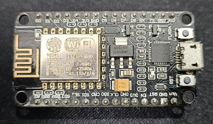
The control of the signals is done by NodeMCU microcontrollers.IthasUSBconnectionoranoutsidecircuit source. Externalpowercanbeprovidedviaabatteryoran AC-to-DCadaptor(otherthanUSB).Thepowerjackonboard canacceptacenter-positiveplugforconnectiontoadapter. BatteriesleadscanbeinsertedintotheGroundedandVin pinconnectorsofthePOWERconnector.Theesp8266hasa 3.3Vnominalvoltage.
TheNodeMCUESP8266developmentboardcomes withtheESP-12Emodule,whichhousestheESP8266chip andTensilicaXtensa32-bitLX106RISCmicroprocessor.The clockfrequencyrangeforthismicrocontrolleris80MHzto 160 MHz, and it supports RTOS. For storage data and programmes,NodeMCUhas4MBofFlashstorageand128 KBofRAM.ItisperfectforIoTprojectsbecausetoitspotent CPU,built-inWi-FiandBluetooth,andDeepSleepOperating features.
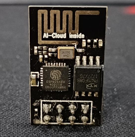
ESP-01getsconnectedtothenodeswheneveritisin therangeofnodeslettingthemasternodetosendagreen signal.Figure4hasimageofESP-01Module
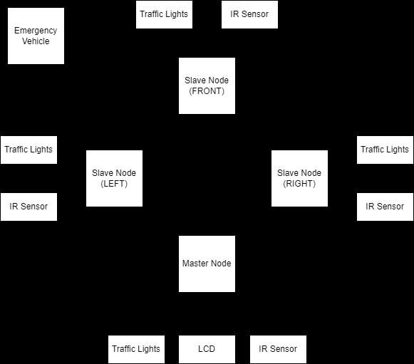
An IR Sensor is connected to each of the 4 nodes, whicharearrangedas1MasterNode,3SlaveNodes,and1 inthemiddle.Anelectronicdevicecalledaninfraredsensor detects some aspects of its environment. The heat of an objectanditsmotioncanbothbedetectedbyanIRsensor. Oureyescannotseetheseradiations.Aninfraredsensoris able to find it. IR transmitter and IR receiver are the componentsofthesesensors.Thesearegoingtobeinstalled at specific intervals on both sides of the road, and they'll counthowmanycarsareusingeachlane.
Either a Micro USB port or the VIN pin (External SupplyPin)canbeusedtopowerNodeMCU.TheUART,SPI, and I2C interfaces are supported. For the open source NodeMCU firmware, present are free prototype board designsareavailable. Thewords"node"and"MCU"(microcontrollerunit)arecombinedtoformthename"NodeMCU".
Theprototypingboarddesignsaswellasfirmware are open sources. Lua is a script used by firmware. The firmwarecreatedbyESP8266EspressifNon-OSSDKthatis developed on eLua project. It heavily utilizes open source applicationssuchasSPIFFSandlua-cjson.Usersmustchoose the modules needed for the application and create a firmware specific to their requirements due to resource limitations. Furthermore, 32-bit ESP32 compatibility has indeedbeenadded.
Thecommonformofprototypinghardwareisadual in-linepackage(DIP)thatincludesaUSBcontrollerwithjust atinysurface-mountedboardhousingtheMCUandantenna. ThechoiceoftheDIPformatmakesbreadboardprototyping
easier. The ESP-12 module of an ESP8266, an IoT implementation Wi-Fi SoC with a Tensilica Xtensa LX106 core,servedasthedesign'soriginalfoundation.
Therequiredvoltageforstablefunctioningis2.5V, witha3.6Vupperlimit.Therefore,thevoltagelevelshould bebetween2.5and3.6VforESP8266tooperatesafely.The highestcurrentanesp8266chipusesis170mA.
appropriatewaybyshowinglightsofastandardcolor(red, amber or yellow, and green) in keeping with the colour scheme.Awarningindicationisayellowlamp.Thestopsign is a red lantern. The indicated path is open for traffic to moveforwardwhenthelampisgreen.
NodeMCUESP8266isutilizedinthisworkduetothe aforementioned specification. The NodeMCU ESP8266 Microcontroller Board is depicted in Figure 6. All of the nodes have these boards. Currently, lane 2 is more congestedthantheotherlanes,sothemicrocontrollergives lane2agreenlightwhilegivingtheotherlanesaredlight. On the LCD connected to the master node, these will be displayed.
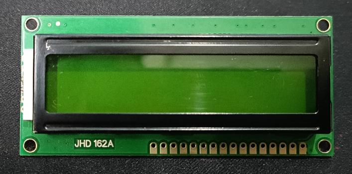
An LCD is a type of visible image-producing electronicdisplaymodule.Acommonbasicmodulefoundin DIYprojectsandcircuitsisthe16x2LCDdisplay.Adisplay with16charactersineachlineistranslatedinto2ofthose linesusingthe16x2formula.16x2LCDisshowninFigure7. Computers, calculators, televisions, mobile phones, and digital watches are some examples of LCD-using devices thatshowthesomedata.
4. RESULTS
ArduinoIDE1.6.5andCircuitoarethesoftwaretools used for implementation of this project. Arduino IDE is crucial tool for writing code for the microcontrollers. Circuito.ioisatoolforcreatingcompleteelectroniccircuits online.TheCircuitoappgeneratesschematicsandcodefor electronic circuit instantly and precisely. Following the selectionofthefundamentalbuildingblocks,itcalculatesall theelectricalrequirementsofourchoice.
Then, in response to controller commands, traffic lightsbegintoglow.Signalizedtrafficlightsaredepictedin figure 8. These lights are used to alert people in the
The figure 9 shows the master node. This node is connected to LCD, traffic signal and IR sensor. The master node is responsible for making decisions for all the traffic lights. The master node’s code consist of an asynchronous webserverandRESTfulAPIwhichisresponsibleforallthe communicationbetweenallthenodes.
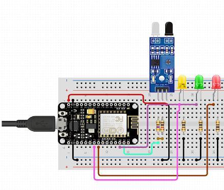
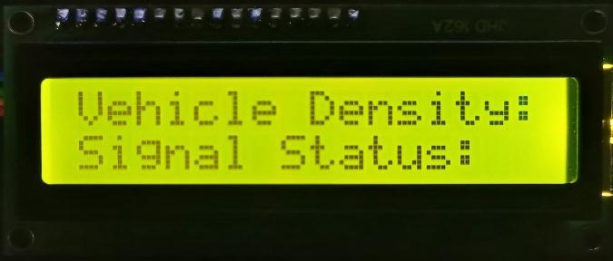
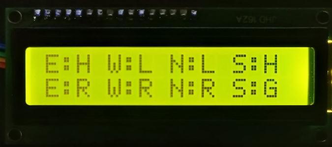
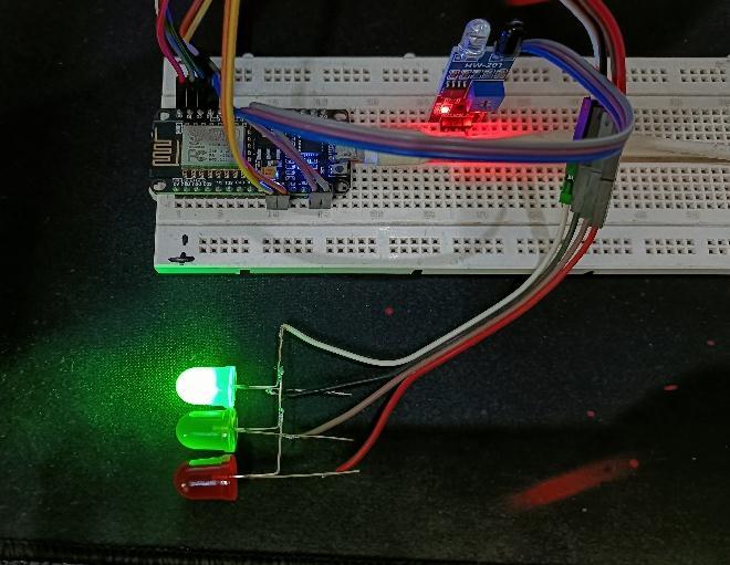
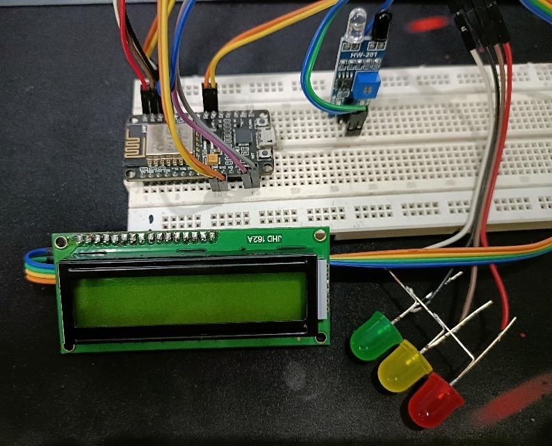
Fig -10: CircuitdesignforSlavenode

Thefigure10showsslavenode.Therearetotalof3 Slave nodes. Each slave node is associated to traffic signal lights and IR sensor. Wi-Fi is used to link slave nodes to masternode.Theslavenodes’codesendthetrafficdensityto the master node. All nodes also create an access point to which emergency vehicles can connect to and the green signalcanberequestedthroughtheconnectednode.
ESP01isdirectlyconnectedtopowersupplyinthe emergencyvehicle.ESP01consistsacodewhichenableitto connecttothenodes.
4.2 HARDWARE SETUP
Fig -12: OutputonMasternode’sLCD
Thefigure12displaystheLCDdisplayoutputfrom themasternode.Here,thefirstrowdisplaysthenumberof vehicles,andthesecondrowdisplaysthestatusofthetraffic signal. Here, the traffic signal position is indicated by the letters "E," "W," "N," and "S," which stand for East, West, North,andSouth,respectively.LowandHigh,respectively, aredenotedbytheletters"L"and"H".Rstandsforred,andG standsforgreen.
Fig -11: HardwaresetupforMasternode
The figure 11 refer to H/W setup of Master node usedforthisproject.Thisnodeisthemostimportantpartof theproject.
-13: HardwaresetupforSlavenode
Thefigure13refertoH/WsetupforSlavenodeused forthisproject.Thereare3slavenodesinthissystem.
5. CONCLUSION
Daily traffic collisions occur in our nation. In this project,anintelligentcontrolsystemisdesignedtolessen trafficblockagesandunwelcometimedelays.Thisproject couldbeveryusefulinareaswithtrafficsignalsaswellas manyotherlocationswhereautomationisrequired.Future plansshouldincludeputtingtheconceptbehindthisproject into action. And this might cause a new change in traffic managementmechanism.
REFERENCES
[1] Chandramohan, J., Nagarajan, R., Satheeshkumar, K., Ajithkumar, N., Gopinath, P. A., & Ranjithkumar, S. (2017). Intelligent smart home automationandsecuritysystemusingArduinoandWifi. International Journal of Engineering and Computer Science,6(3).
[2] Yang,Bo,RenchengZheng,KeisukeShimono,Tsutomu Kaizuka,andKimihikoNakano."Evaluationoftheeffects ofin-vehicletrafficlightsondrivingperformancesfor unsignalised intersections." IET Intelligent Transport Systems11,no.2(2017).
[3] M. F. Rachmadi et al., "Adaptive traffic signal control system using camera sensor and embedded system," TENCON2011-2011IEEERegion10Conference,Bali, 2011, pp. 1261- 1265. doi: 10.1109/TENCON.2011.6129009
[4] S. N. Mahalank, K. B. Malagund and R. M. Banakar, "DevicetodeviceinteractionanalysisinIoTbasedSmart Traffic Management System: An experimental approach,"2016SymposiumonColossalDataAnalysis and Networking (CDAN), Indore, 2016, pp. 1-6. doi: 10.1109/CDAN.2016.7570909
[5] T. Roopa, A. N. Iyer and S. Rangaswamy, "CroTISCrowdsourcingBasedTrafficInformationSystem,"2013 IEEEInternationalCongressonBigData,SantaClara,CA, 2013, pp. 271-277. doi: 10.1109/BigData.Congress.2013.43
[6] Rajak,B.,&Kushwaha,D.S.(2019).TrafficControland Management Over IoT for Clearance of Emergency Vehicle in Smart Cities. In Information and CommunicationTechnologyforCompetitiveStrategies (pp.121-130).Springer,Singapore.
[7] D.Manoj “Density Based Traffic Control System” electrical & electronics engineering Department mahatma Gandhi institute of technology Chaitanya BharathiP.O.,Gandipet,Hyderabad–500075 2012
[8] B.Prashanthkumar,b.Karthik“microcontrollerbased traffic light controller”, Department of Electrical & ElectronicsEngineeringgokarajurangarajuinstituteof engineering&technology,2011
[9] SachinJaiswal*,TusharAgarwal*,AkankshaSingh*and Lakshita*”IntelligentTrafficControlUnit”,*Department of Electronics and Communication Engineering, Bharati Vidyapeeth‟s College of Engineering, PaschimVihar,NewDelhi-110063
[10] Rijurekhasen, Andrew Cross, adityavashistha, VenkataN.Padmanabhan,EdwardCutrell,andWilliam
Thies “Accurate Speed and Density Measurement for RoadTrafficinIndia”IITBombay
[11] Cihan Karakuzu. “Fuzzy logic based smart traffic lightsimulatordesignandhardwareimplementation”. Kocaeli University,EngineeringFaculty,Electronics
[12] Chandrasekaran, G., Periyasamy, S., & Rajamanickam,K.P.Minimizationoftesttimeinsystem onchipusingartificialintelligence-basedtestscheduling techniques.Neural Computingand Applications,1-10. https://doi.org/10.1007/s00521-019-04039-6.
[13] Highway traffic model-based density estimationIEEE paper by Morarescu, Nancy Univ., France, publishedinAmericanControlConference(ACC),2011.
[14] MusaMohdMokjiandSyedAbd.RahmanSyedAbu Bakar, “Directional Image Construction Based on Wavelet Transform for Fingerprint Classification and Matching”,NationalConferenceonComputerGraphics andMultimedia,pp.331–335,2002.
[15] Naik, T., Roopalakshmi, R., Ravi, N. D., Jain, P., & Sowmya,B.H.(2018,April).RFID-BasedSmartTraffic Control Framework for Emergency Vehicles. In 2018 Second International Conference on Inventive Communication and Computational Technologies (ICICCT)(pp.398-401).IEEE.
[16] Bhate,S.V.,Kulkarni,P.V.,Lagad,S.D.,Shinde,M.D., & Patil, S. (2018, April). IoT based Intelligent Traffic SignalSystemforEmergencyvehicles.In2018Second InternationalConferenceonInventiveCommunication and Computational Technologies (ICICCT) (pp. 788793).IEEE.
[17] Zhang, K., Sheng, Y. and Li, J., 2012. Automatic detectionofroadtrafficsignsfromnaturalsceneimages based on pixel vector and central projected shape feature.IETIntelligentTransportSystems,6(3),pp.282291.
[18] Yapp, J. and Kornecki, A.J., 2015, August. Safety analysisofvirtualtrafficlights.InMethodsandModels in Automation and Robotics (MMAR), 2015 20th InternationalConferenceon(pp.505-510).IEEE.
[19] Yang, Bo, Rencheng Zheng, Keisuke Shimono, TsutomuKaizuka,andKimihikoNakano."Evaluationof the effects of in-vehicle traffic lights on driving performances for unsignalised intersections." IET IntelligentTransportSystems11,no.2(2017)
[20] Higaki, H., 2014, March. Virtual Traffic Signals by CooperationamongVehicle-MountedMobileComputers. In New Technologies, Mobility and Security (NTMS), 20146thInternationalConferenceon(pp.1-6).IEEE.