Unbalanced Voltage Impacts and its Analysis on an Induction Motor
Vyshnav S B1 , Abhishek Vinod2, Denil Paul3 , Karthik R Ashok4, Sudheer P N51,2,3,4 Student, Dept. Of mechanical Engineering, Alva’s Institute Of Engineering and Technology, Karnataka, India

5 Professor Dept. Of mechanical Engineering, Alva’s Institute Of Engineering and Technology, Karnataka, India ***
ABSTRACT
Lacks like unequal voltages in the voltage source could bringaboutissueslikeextrememisfortunes,overvoltage mechanical motions, and impedance with control hardware.Recognizingtheseuniquemachinesituationsis crucial inthe electrical machine'scollaboration with the powermatrix.Thisinvestigationstudiedtheinfluenceof unequalvoltagesonmotorexecution.Then,atthatpoint, checking this unfortunate condition utilizing electrical machineboundariesisdone.Forthissituation,themotor itselfcangoaboutasthesensorthatdistinguishesunusual circumstances. Furthermore, this paper studies the detrimentalimpactsofunevenThisrepresentsasinusoidal voltagewhichisfrequentlyseeninpowersuppliesvoltage, onacceptancemotorpresentationintermsoflineflows, powerelement,andproficiency.
Keywords- Unbalanced voltage, Induction motor, DeratingCurve.
1. INTRODUCTION
Inductionmotorsarefrequentlyemployedincommercial andindustrialsettings.Venturesincorporatevehicleand semiconductor fabricating plants, emergency clinics, broadcasting offices, and so on. Uneven stock voltage makes unfriendly impacts on the electrical mechanical assembliesparticularlytheelectricalmotors.Asymmetrical transformer winding, unbalanced loads, or huge singlestage loads can all create voltage unbalance. Albeit the voltageunbalancesislittle,hugeunevencurrentstreams because are of moderately little negative arrangement impedance. This high current produces overheating, furtheraccidents,vibrations,auditorydisturbance,aloss inforce,andadecreaseinthelifeofaninductionmotor[6, 7].
Theeffectsofunevenvoltageoninductionmotortorque, speed,andcurrentwhenthevoltagesize,stagepoint,or botharemodifiedatthesametimearediscussedinthis paper. The NEMA, IEEE, and power local area networks havespecifiedthevoltageimbalance.Oneofthedefinitions isfrequentlyusedfortheinductionmotortest,andthey areallpresentedhere.Atthispointwhennolessthanone ofthestockpilequalities(abundanceaswellasstagepoint) goesamissfromtheguidelines,theelectricalframeworkis impactedbytheunbalancevoltage[11].
The induction motor (IM) is broadly utilized in the industry since it gives great execution as well as high unwaveringqualityandsolidness[1,2].IMscanbelocated in numerous applications which makes strenuous conditions. Working under these circumstances antagonistically influences IMs execution [3].IMs shortcoming finding is vital, as it keeps away from sensational outcomes to the actual machine and to the generalclimate.Thefollowingareasomeoftheimportant flawsthatcanaffecttheoperationofelectricalmachines: (1) problems with the stator, caused by the opening or loosingofatleastoneturn;(2)unexpectedaffiliationofthe statorwindings;(3)brokenrotorbarsorbrokerotorendrings; (4) static or potentially strong air-hole impetuousness; (5) twisted shaft (similar to dynamic whimsy), which can cause serious damage to the stator coreandwindings;(6)shortedrotorfieldwinding;and(7) failureswiththeheadingsandgearboxThisessayfocuses onthestatordeficits,whicharecausedbyafewvarious stressorsandareprimarilygroupedintofourcategories. [5]
The legitimate utilization of the power by the induction motorasaframeworktoencounterburdenprerequisites is always a subject of extreme interest [1]-[13]. Most modernmotorshaveintendedfor460Vactivity,still,the utilization of the dissemination framework to intend for 480V.Sothereasoningoverhereisthatthelinkvoltage dropwillpermitthelegitimatevoltageof460Vwhichis presentatthemotorloadpoints.Estimationshasappeared to be disregarding the link falls, the motor terminal voltagescanbeconsiderablymorethanthe460Vinfirm modernframeworks,whileitcouldbewellunderneaththe ostensible voltage, where the framework is vigorously stackedinpowerlessbusiness
2. Losses in electric motor
Byusingtheproper,similarcircuitcomputations,thesame statorandrotorflowsandcorrespondingcopperlossesat each heap or slipknot are completely fixed. This contact andwindagelosseswhichgenerally1-2%oftheevaluated output.Thenoheapprimarylossesareespeciallysubject to quite a large number of highlights of the plan, yet an unpleasant normal 2-3% of the examined output is this number. Ingeneral,therateofcorelossesdecreaseswhen thespaceopenings,theratiooftherotortostatorspaces, orthelengthoftheairholearereduced.Ahugeextentof thiscentermalfunctionandthewandererloadlossesisJ.
Faiz et al. /Energy Transformation and The board 47 (2006) 289-302 291 ordinarily because of space recurrencethroblosses,withthegoalthatexcellentsilicon steel is generally utilized for center laminations. Typical upsidesofstraycentermalfunctionare1-2%oftheresult [8,9].
3. Effect of Unbalanced Voltage on Losses
Voltage unbalances and mechanical over-burden create extremeoverheatingonacceptancemotors[12,13].The overheating brought about by these two peculiarities is createdbytheadditionofcurrentinthemotorwindings [14, 15]. This augmentation is requested by the actual motor to keep up with the force in the rotor [5, 7]. Moreover, a decrement in the rotor speed is gotten, creating a deficient cooling [7]. The warm addition adverselyinfluencesthemotorlifetime,rotorandstator guides, center, protection, and orientation, creating irreversible harm when the motor warms past its plan limits.
Voltage unbalance condition is introduced when the voltagesizesofathree-phaseframeworkareinconsistent aswellasvaryfromoneanotherbyaphase’spointof120 degrees[13].Voltageunbalancecanbeassessedutilizing the voltage unbalance rate (%UNB) as indicated by the IEEEstandard[7].Itischaracterizedasfollows:
opposition is also well understood, its variations under balanced and unbalanced situations may be taken into consideration In light of the complex voltage unbalance factor,orCVUF,definition,theproposedmotorisbroken downoverfullloadand0-6%unbalancedvoltage,andthe differentlossesareassessed.Naturally,withthemeaning ofCVUF,guaranteeofthenormallinevoltageisnecessary toprovidepreciseresultsfromtheanalysis,disregarding the imbalance point. With a point = 120 and a normal voltage corresponding to 380 V, the imbalance of the terminal voltage will be taken into consideration in this case.Asregular,ithasexpectedthatthisnormalterminals voltage in modern plants is lower than the evaluated esteem.
This builds the warm stress in the machine and will prompt malfunction throughout everyday life, while perhapsnotanearlydisappointment.Thisisexpectedfirst andforemostaredecreaseoverthesizewherethepositive arrangement voltage is contrasted with the uneven contributed voltage. Furthermore, the existence of this negative grouping moving charge makes a negative groupingforcewhichdeductsfromthepositivegrouping forcetorelentanetforcewhichisthemoremodest.
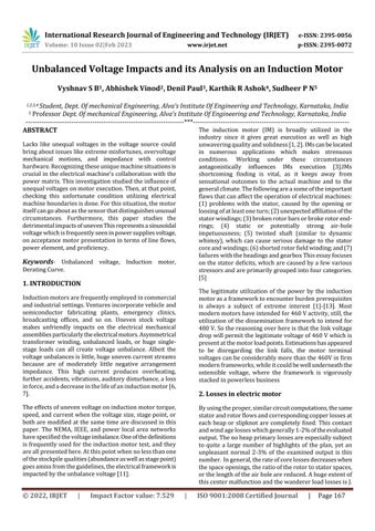
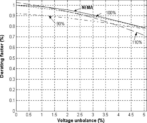
4. Derating Curve of the IM
Where U+ and U-are the positive and negative balanced parts, individually, which are gotten through the Quick FourierChange(FFT)andtheFortescuechange.
Notwithtendingthepositivesuccessionpart,thenegative arrangementpartofthiscurrentfurthermore,oneofthe main causes of the increase in machine losses is the differentiationofthephaseflowsinthesituationofuneven voltage.Iftheentirelossesofanacceptancemachineare separated into three groups, such as the copper losses (statorandrotor),corelosses,andmechanicallosses,the inconsistentvoltagehasthe biggesteffectonthecopper lossesandthesmallesteffectonthemechanicallosses.
To examine this exhibition motor with three stages provided by an uneven voltage, what’s more, envisionitsimpactBasedonthemachine'slosses,a7.5kW three-phase enlistment motor with the specified specifications is suggested. Summarizes the exhibition circumstanceswhilethemotoroperateswith4%slipand estimatedyieldpower. Statorcopperlosses,rotorohmic losses, core losses, mechanical losses (contact and windage),andstraylosseshaveallbeentakenintoaccount in the malfunction evaluation for the unequal voltage supply.Themanufacturerhastakenintoconsideration100 W in mechanical losses. Given that the core losses
Working a motor for an extended length of time in an imbalanced voltage state exceeding 5% "is not recommended," according to NEMA standards. The imbalance state causes a motor to operate blazing. The NEMAstandardstatesthatdamagepreventionisnolonger required when the imbalance hits 5% since the temperature begins to increase so quickly at that point. Themostfundamentalprotection,accordingtoNEMA,isto de-ratethemotor tolowertheresultdrawloadsothat itisabletowithstandtheadditionalheatproducedbythe imbalanced accumulation. That has various ways to encourageaderatingcurve.Basedonseveralexperiments with various motors and adjusted voltages, one of them claims that when voltages are imbalanced, the % incrementintemperatureclimbingclimbstoalmosttwice thesquareofthepercentagevoltageimbalance.According to one of them, when voltages are unbalanced, the temperatureincreasesbyapercentagethatisalmosttwice thesquareofthepercentageofthevoltageimbalance.In theend,itisstilluncertainwhatderatingwillbeneededto keep the machine's temperature rising. This imbalance derating curve (NEMA definition) Fig 1. The motor shouldn'trunatmorethan77%ofitspredictedpower,for example,witha5%imbalance.
In ideal supply circumstances, Comparing LSPMM improvements to IE2 and IE3 class motors, lower operating temperatures are achieved. Large current unbalancesareformedunderVUcircumstances,increasing motor losses and hence the temperatures inside and outside. To investigate the VU influence on motor
temperaturewithunderandovervoltage,thermographic picturesindicatingFigures18and19illustratetheresults foreachVUconditionfortheLSPMMfortheexpansionof this parameter in the motor end shield The images demonstrate the behavior of 1% of VU at low and high voltage. Causes no obvious changes in LSPMM temperature,provingthatmotoroutputpowershouldnot bereduced.
used in conjunction with over- or under-voltage. As the voltageimbalancegrows,thecenterissueintensifies.The warm model, which was introduced, was favorably appreciated.Simpletestswereperformedtodetectwarm boundaries, rather than motor plan information. In the instance presentation the heated model performed admirably in testing with variable voltages, uneven voltages,andover-andundervoltages.Bothfleetingand recurring occurrences might be predicted by the model.
5. Consideration of Overvoltage and under voltages in the Derating Curve
OvervoltageandUndervoltageontheNEMAderatingcurve wereaccommodatedbytheelectricalandheatedmodels. Motorlossesarecalculatedusingtheelectricalmodel.To account for these losses and anticipate the increase in motortemperature.
Temperatures at the exactness of case 2. The derating curve takes into account overvoltage and undervoltage. The curves were created by carrying out the three followingscenarios:InCase1,amotorwassubjectedtoan imbalancedvoltageatthenormalvoltage.Ifboth2anda 10% overvoltage in addition to up to 5% in unbalanced voltages were applied to the motor. In Example 3, 10% undervoltageandupto5%irregularvoltageswereapplied toamotor.Whensuppliedbyadjustedassessedvoltages, themotor'sevaluatedtemperaturewasknownatfullload themotorconnectionsreceivedtheselectedvoltages.At full load, a high stator twisting temperature was anticipated. To keep the temperature at the appraised level,themotoryieldpowerwasloweredfortemperature valuesovertheassessedlevel.Thederatingstillupinthe airastheproportionofthedeterminedyieldcapacitythat evaluatedpowerThemotorissupposedtobeprotectedby thederating's100percentcurvewhenitreceivesCase1 voltages.Asmightbepredicted,theNEMAcurveandthis curve are extremely similar. When Case 2 voltages are applied,the110%curvewillprotectthemotor.Lessthan 1% of an imbalance allows the motor to operate at maximum power. This is equivalent to the NEMA curve. The motor cannot be run at more than 71% of its rated power witha 5%imbalance.WhenworkingwithCase3 voltages, the 90% curve is the derating curve that will prevent motor twisting from overheating. Regardless of voltage imbalance, the 90% curve recommends that a motorbederatedifitisanticipatedtooperateatfullload whenunder10%Undervoltage.Thederatingforthe90% Undervoltageand100%evaluatedvoltagecurvesisalmost the same at 5% imbalance. This is expected because the Undervoltage scenario’s bigger and lower core losses compensatefortheanalyzedcase'slowerandhighercore losses,resultinginthecorrespondingderatingatthattime [16].
The no-heap and locked rotor tests have left the motor spinning.Thecorelosseswerecorrectedtentatively.When
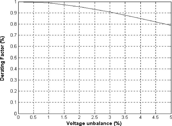
Fig.3(a)Positivesequenceequivalentcircuit
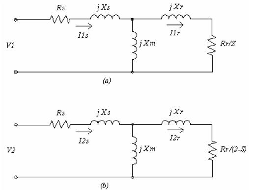
Bybreakingdownathree-phaseimbalancedsysteminto two sets of balanced signals and a set of single phase phasors or symmetrical components, symmetrical component analysis makes fault analysis simpler. The positive,negative,andzerosequencecomponentsreferto these stages. The use of symmetrical components in relationtothree-phaseelectricpowernetworksfacilitates the investigation of imbalanced situations. A large inductionmotorisespeciallysusceptibletosupplyvoltage imbalance. A defect in voltage imbalance is significant because an imbalanced voltage source can produce excessive losses, heating, noise, and vibration. It is necessary to resolve the problem of unbalance in the voltagesupply.Thisstudyanalysisofaninductionmotor operatinginanunbalancedvoltagesupplyispossible
(b)UseaNEMA[32]negativesequenceequivalentcircuit [16]forthisVUsituation.Theworstrecordedconditions are 3% and 4% overvoltage unbalances (Figure 19, c-f), whicharemoreharmfultothetemperatureofthismotor thantheVUwithUndervoltage.
Figure20depictsthetemperaturefluctuationforthethree IMsinthesixsituationsstudied.TheIE2classmotorhas an insulation class (maximum temperature of 130 C), whereastheIE3andIE4classmotorshaveinsulationclass F (maximum temperature of 155 C), indicating a better tolerance for temperature rises. The results, however, show that the IE4 and IE2 class motors have lower operatingtemperaturesthantheIE3classmotor.Figure 20(a,c,ande)demonstratesthattheVUwithlowvoltage doesnotresultinanIE4classmotor.
DIFFERENT LOSSES IN 3-PHASE INDUCTION MOTOR
Copper loss:Thiscopperlosshappensmostlyinthestator and rotor windings. It is the I^2R loss in winding in the windingresistivecomponentsthatarepresent.Inwhich thecurrentpasseswhereI^2Rlosswilloccurintermsof heatinthewinding.Thislossisvariablelossduetoload varyingthecurrentvariesandI^2Ralsovaries.Duetothe
lengthcoilextension,thislosscanbeincludedanddueto the loss of copper wire in the slot copper loss is more proven to occur. In the copper losses, there are stator copper losses and rotor copper losses in the 3-phase induction motor where these stator copper losses are calculatedaccordingtotheIECnormbyusinganequation ofthetestresistanceRHandcurrentIHrate[25,26].
Ps=1.5RHI^2H=3RPHI^2H
Inthisexample,IHdenotesthestatorphasecurrentand RH denotes the winding line-to-line resistance, as both equations provide the same answer when the phase resistanceRPHisused.Theserotorwindinglossesareslip (s)relatedandaregenerallycalculatedusingtheequation.
Pr=(P1-PS-PFe)S
P1representstheelectricinputpower,PSrepresentsthe statorwindinglosses,PFerepresentstheno-loadironloss, andSrepresentstheslip.[26]
Iron or core or Magnetic loss: This iron or core loss occurs mostly on an induction motor's stator and rotor cores. This type of loss is sometimes referred to as core loss or magnetic loss. A core loss or magnetic loss is anothernameforthiskindofloss.Eddycurrentlossand hysteresis are combined in this situation. The supply frequency,aswellasthefluxdensityinthestatorandrotor cores, influence both of these losses. The hysteresis loss (consideringanironcorewithawindingandconnectedto anACsupplyusingtheright-handthumbrulethecurrent passes anti-clockwise direction and magnetic flux is upward. In the negative half cycle, the situation has reversed the Sis on the right and north on the left. The situation is called magnetic reversal it is a land of work donewhentheenergylosstakesplace.Thisenergylossis calledhysteresisloss[23,24,28].Intheeddycurrentloss whentheACsupplyhappensfluxisgeneratedtheACflux duetoACfluxtheEMF(electromagneticflux)isinducedon the iron core surface. This EMF causes an eddy current core surface. Due to this I^2R loss and resistive loss is occurred in form of heat this loss is called eddy current loss.Alaminatedcorecanbeusedtoreduceeddycurrent loss[29,30].
Mechanical losses: mechanical losses in a three-phase inductionmotormainlyoccurduelossduetofrictionand loss of windage. In this friction loss, these losses occur whenthetwosurfacesareincontactwitheachotherand haverelativemotionwitheachother.Thisfrictionalloss mainlyoccursinthebearingofthemotorandthislosscan be reduced with the help of good lubrication. And the windage losses are caused by the air disturbance in the movingpartsoftheinductionmotor.Byreplacingtheold partswithacylindricaldesignofthemovingpartsthisloss canbeminimized.Inthecylindricalparts,airdisturbance islesssowindagelosscanbereduced.Mechanicallossis
constant, the magnetic losses are also constant this mechanicalplusmagneticlosscreatesastraylossallthese losses occurs in term of heat [31]. And other additional load losses are also found in the three-phase induction motorduetotheunbalancedcondition.
CONCLUSION
Voltages this research investigated the derating of acceptancemachineswhensuppliedbyunevenvoltagesin combinationwithover-and-under.Abroadinvestigationof theuniquemeaningsofunequalinventoryhasuncovered that the distinctions in the definitions don't bring about critical derating contrasts at the point when worked by unequalsuppliesinthe5%territory.Positiveandnegative successioncircuitswereintroducedandtheeffectonthe general force speed curve made sense. The negative groupingforcediminishesthebeginning,pinnacleandfull burdenappraisedforce,inthiswayexpandingbeginning time,loweringthemotor'slist-cyclingspeed,andmakingit operateatahigherslip.Forderatingacceptancemachines, the NEMA curve has been expanded to accommodate overvoltage and Undervoltage. Themis voltage and temperaturedatahavebeencomputedindependentlyfora machine running with 10% overvoltage or 10% under voltage using the electrical and heated models. The derating factor for safe activities is not absolutely fixed. Therewerealsotwocontextualstudies.
REFERENCES
[1]P.Pillay,“Practicalconsiderationsinapplyingenergy efficientmotorsinthepetrochemicalindustry,” IEEE IAS Mag.,vol.3,pp.32–40,Jan./Feb.1997
[2] R. F. Woll, “Effect of unbalanced voltage on the operationofpolyphaseInductionmotors,” IEEETrans. Ind. Applicant.,vol.IA-11,pp.38–42,Jan./Feb.1975.
[3]Williams.Operationofthree-phaseinductionmotorson unbalanced voltages.AIEE Trans, Pt-III-A, and Power ApparatusSyst1954;73(April):125–33.
[4] Gafford WC, Duestenhoef, Mosher CC.Heating of inductionmotorsonunbalancedvoltages.AIEETrans,PtIIIA,PowerApparatusSyst1959;PAS-78(June):282–97
[5]“ComparisonofapplicationcapabilitiesofUandTrated motors,” IEEE Trans. Ind. Applicat.,vol.IA-11,pp.34–39, Jan./Feb.1975.
[6]AnaBarbaraFernandesNeves,AnesiodeLelesFerreira Filho, MarcusVinicius Borges de Mendonca, “Effects of Voltage Unbalance on Torque and Efficiency of a ThreephaseInductionMotor”,16thIEEEconf.onHarmonicsand QualityofPower,May2014,pp.679–683
[7]EnriqueC.Quispe,IvanD.Lopez,“EffectsofUnbalanced Voltages on the Energy Performance of Three Phase Induction Motors”, IEEE conf. on Power Electronics and PowerQualityApplications,July2015,pp.1-6
[8]SpoonerT,KincaidCW.Noloadinductionmotorcore losses.TransAIEE1928;48(April):645.
[9]SpoonerT.Squirrel-cageinductionmotorcorelosses. TransAIEE1925;44:155.
[10]Nandi,S.;Toliyat,H.A.;Li,X.Conditionmonitoringand faultdiagnosisofelectricalmotors Areview.IEEETrans. EnergyConvers. 2005,20,719–729.
[11]Alwash,J.H.H.;Ikhwan,S.H.Generalisedapproachto theanalysisofasymmetricalthreephaseinductionmotors. IEEEElectr.PowerAppl. 1995,142,87–96.
[12]J.L.Gonzalez-Cordoba,D.Granados-Lieberman,R.A. Osornio-Rios, R. J. Romero-Troncoso, J. J. De SantiagoPerez, and M. Valtierra-Rodríguez, “Methodology for overheating identification on induction motors under voltageunbalanceconditionsintheindustrialprocess,” J. Sci. Ind. Res.,vol.75,no.2,pp.100-107,Feb.2016.
[13]P.Gnacinski,“Windingstemperatureandlossoflifeof aninductionmachineundervoltageunbalancecombined withover-orundervoltages,” IEEE Trans. Energy Convers., vol.23,no.2,pp.363-371,Apr.2008.
[14]R.M.Tallam,B.L.Sang,G.C.Stone,G.B.Kliman,Y.JiYoon,T.G.Habetler,andR.G.Harley,“Asurveyofmethods for detection of stator-related faults in induction machines,” IEEE Trans. Ind. Appl., vol. 43, no. 4, pp. 920933,July2007.
[15] A. Siddique, G. S. Yadava and B. Singh, “A review of stator fault monitoring techniques of induction motors,” IEEE Trans. Energy Convers., vol. 20, no. 1, pp. 106-114, Feb.2005.
[16] Derating of Induction Motors Operating with a Combination of Unbalanced Voltages and over or under voltages Pragasen Pillay, Senior Member, IEEE, Peter Hofmann,andMarubiniManyage.
17.Venkataraman,B.;Godsey,B.;Premerlani,W.;Shulman, E.; Thaku, M.; Midence, R. Fundamentals of a motor thermalmodelandItsapplicationsinmotorprotection.In Proceedingsofthe58thAnnualConferenceforProtective RelayEngineers,Jacksonville,FL,USA,5–7April2005.
18.Lei,G.;Zhu,J.;Guo,Y.;Liu,C.;Ma,B.AReviewofDesign Optimization Methods for Electrical Machines. Energies 2017,10,1962.[CrossRef]
19.Bouzid,S.;Viarouge,P.;Cros,J.Real-TimeDigitalTwin of a Wound Rotor Induction Machine Based on Finite ElementMethod.Energies2020,13,5413.[CrossRef]
20. Gnacinski, P. limczak, P. High-Power Induction MotorsSupplied withVoltageContainingSubharmonics. Energies2020,13,5894.
21. Asad, B.; Vaimann, T.; Belahcen, A.; Kallaste, A.; Rassõlkin,A.;Iqbal,M.N.TheClusterComputation-Based HybridFEM–AnalyticalModelofInductionMotorforFault Diagnostics.Appl.Sci.2020,10,7572.[CrossRef]
22] A. M. Bazzi and P. T. Krein, "Review of methods for real-timelossminimizationininductionmachines,"IEEE Trans. Ind. Appl., 2010. Rated Load. Energies 2018, 11, 2024.
23.Jeong-JongLee,Soon-OKwon,Jung-PyoHong,Ji-Hyun Kim,Kyung-HoHa,"CoreLossDistributionofThree-Phase Induction Motor Using Numerical Method", IEEE Conferences, INTELEC-31st international telecommunicationsenergyconference,pp.1–4,2009.
24.T.Marcicetal"Theimpactofdifferentstatorandrotor slotnumbercombinationsonironlossesofathree-phase induction motor at no-load" Journal of Magnetism and MagneticMaterials,vol.320,no20,pp.891-895,2008.
25.EstimationofCopperandIronLossesinaThreePhase InductionMotorusingFiniteElementAnalysis574–583.
26.A.G.Yepes,J.Doval-GandoyandH.A.Toliyat,"Strategy with smooth transitions and improved torque-speed regionandstatorcopperlossfortwo-levelasymmetrical six-phase induction motor drives under switch faults", IEEE Trans. Power Electron.,vol.36,no.2,pp.19541969,Feb.2021.
27.Cardoso,A.J.M.;Cruz,S.M.A.;Fonseca,D.S.B.Inter-turn stator winding fault diagnosis in three-phase induction motors, by Park’s vector approach. IEEE Trans. Energy Convers.1999,14,595–598.
28.D.M.Ionel,MohammedH.Yasen,M.Popescu,“Factors Affecting the Accurate Prediction of Core Losses in Electrical Machines", IEEE International Conference on Electric Machines and Drives, pp. 1625 – 1632, 2005. Trans.PowerDeliv.2015,30,693–703.[CrossRef]
29.TongYang;LibingZhou;WeiJiang,"CalculationofEddy CurrentLossesinaSolid-RotorCageInductionMotorby FiniteElementAnalysis",IEEEConferencesonElectrical MachinesandSystems,pp.3656-3659,2009.
30. atsumi and Noriaki, “Iron Loss Model for Rotating MachinesUsingDirectEddyCurrentAnalysisinElectrical SteelSheets",IEEEtransactionsonenergyconversion,vol. 25,no.3,2010.
31.KonradDabala,"Analysisofmechanicallossesinthreephasesquirrelcageinductionmotors"IEEEConferences, electricalmachinesandsystems,ICEMS,proceedingsofthe fifth international conference, vol.1, pp.39-42, 2001