STRUCTURAL ANALYSIS OF BRIDGES AND PILE FOUNDATION SUBJECTED TO SEISMIC LOADS
Rajesh Kumar Singhal1, Pradyumna Dashora2M Tech, PAHER University Udaipur Assistant Professor, PAHER University Udaipur
Abstract - An Effect of various materials of pile foundation of bridges in response of the seismic loading condition has to be monitored. Such an analysis was required to verify the performance of each structure acting under seismic loads. In this study, a numerical model is developed to evaluate both bridges and pile foundation performance with respect to varying seismic loading conditions. Specifically speaking to evaluate the performance of various structural materials used as pile foundation for bridges against seismic loads. The vibrational behavior of the bridge was also evaluated on the basis of seismic loads on the structure. Furthermore, pile foundation of the bridge was modeled along with combination of soil in order to analyze the behavior of the structure with soil. Also the bridge pile foundation of different structural material namely structural steel, carbon fibre reinforced steel and epoxy fibre reinforced steel were modeled using ANSYS software. It was observed that Carbon fibre reinforced structural steel is superior in performance as compared to that of the structural steel and epoxy fibre reinforced structural steel in both pile foundation as well as development of bridge structure. Maximum nodal displacement for bridge structure with respect to seismic load conditions for different materials were Carbon fibre structural steel as 63.104 mm, Epoxy fibre structural steel as 69.992 mm and Structural steel as 70.091 mm respectively.
Key Words: Carbon fibre structural steel, Epoxy Fibre Structural Steel, ANSYS.
1 INTRODUCTION
Thesesoilpressuresmaycomefrompilesettlement,soilswelling,orpassiveresistancesbroughtonbylateralstresses thesuperstructuretransmitstothepilecaps.Iftheearthdirectlybeneathabuilding'sbaseisincapableofsupportingthe structure,pilesmaybeusedasafoundation.Apilefoundationmaybetakenintoconsiderationifthefindingsofthesitestudy indicatethattheshallowsoilisweakandunstable,orifthesizeofthepredictedsettlementisunacceptable.Additionally,acost estimatecanshowthatapilefoundationislessexpensivethananyothergroundimprovementcoststhatarebeingevaluated. Therearevariouswaystoarrangepilessotheycansupportloadsthatareplacedonthem.Itispossibletobuildverticalpilesto supportbothlateralandverticalloads.Rakingheapsandverticalpilescanbeusedincombination,asneeded,tosustainboth horizontalandverticalforces.Ifapilegroupissubjectedtoverticalforce,thetotalloadisconsideredtobedividedbythe numberofpilesinthegroup,whichisusedtocalculatethedistributionofloadonasinglepilethatisapartofthegroup.Butif agroupofpilesisexposedtolateralload,eccentricverticalload,oracombinationofverticalandlateralload,thegroupmay experiencemomentforce.
Due to the increase in urban population, underground rail transit has developed into one of the main modes of transportation[1].Themajorityofsubwaystations,whichactasthehubsoftransportationforundergroundrailnetworks,are situated in hilly, heavily populated urban regions. One of the biggest issues that regularly affects subway stations during constructionisgroundsurfacesettlement[2-4].Thesebuildingsusuallyhavedeeppilingfoundations,whichmightimpedethe constructionofpipelinesandotherundergroundconstructionslikesubways[5].Pilefoundationshavebeenconstructedfor numerousprojects,includinghigh-risestructures.Itisfrequentlynecessarytousepilefoundationunderpinningtotransferthe existing pile foundation's weight properly in order to maintain the stability of the top construction technology. Thus, undergroundtransportinfrastructures,likesubwaytunnels,areprogressingsmoothly[6].
2 LITERATURE REVIEW
Inordertogeta actual knowledgeofthevarious seismicdesignandpushoverinvestigationapproaches,various researcharticles,designcodesandrelevantbookswerescrupulouslystudiedtounderstandtheeffectofseismicparameterson design&detailingofRCbuildings.Thishelpedindecidingobligatorymodelingmethodsandparameterstobeusedinseismic investigationandcomparisons.KumarandRao(2002)havecarriedoutcorrespondingstationaryinvestigationforafive(G+4) storiedRCbuildinginordertomatchuptothevariationofpercentagesteelwhenthebuildingisdesignedforgravityloadsas perIS456:2000andwhendesignedforearthquakeforcesinalltheseismiczonesasperIS1893:2002.Samyog(2013)has doneastudywhichinvolvescostcomparisonofRCCColumnsinidenticalbuildingsbasedonnumberofStoriesandSeismic

Zones.Thisworkpresentsthatthedetailingofcolumnsofabuildingcoveringcertainplinthareavariesforacombinationof storeyandseismiczone.Anotherfacetofthisstudyinvolvesperformanceevaluationofthedesignedbuildingsforvarious seismiczonesanddetailingprovisionsusingcomputerbased“PUSH-OVER”Analysis.Theneedofsuchanexercisehasbeen well illustrated byGhoshandMunshi(1998) in whichit hasbeenstated thattheaimofthedesigncodesiscardinallyto minimizethelifehazardsand Athanassiadouanalysestwoten-storeyedplanesteppedframesandoneten-storeyedregular framewhichweredesignedasperEurocode8forthehighandmediumductilityclasses.InthisworktheInter-storeydrift ratiosoftheframesandplastichingeformationincolumnsweremonitored.Inthiswork,theresultsofpushoveranalysiswere presentedusing"uniform”loadpatternaswellas"modal‟loadpattern.
Luetal.[8]discoveredthattheSAPconsolidationsettlementispositivelycorrelatedwiththePSSR.Thesettlement characteristicsofthestratumintheconstructionprocessarestudiedanddeterminedthereasonsforthedifferencebetween thenumericalandfieldmonitoringresults[13].ExperimentalstudyandDEMsimulationcarriedoutofthepush-uploadtests, wheresandplugsinsidesteelpipepileswerepushedupwardsusingarigidplaten;testresultsshowedthatthepush-upforce increased significantly with increasing aspect ratio and sand relative density [15]. Xu et al. [20] conducted a series of theoreticalanalysisandnumericalsimulationsoftheentireconstructionprocesstoverifytherationalityoftheschemeandto reducethepotentialconstructionriskofthetechnology.Parketal.[21]proposedandverifiedtheapplicationofthemodified underpinningmethod,whichcanreducetheconstructionperiodby1.5timesandtheconstructioncostby1.2timescompared withtheconventionalpilecuttingtechnology.Horikoshietal.[36]carriedoutaseriesofcentrifugetestsonpiledraftmodels embeddedinsandsubjectedtohorizontalandverticalloadingstostudytheloadsettlementbehaviourandtheloadsharing characteristicsbetweenthepilesandtheraft.Theeffectoftherigidityatthepileheadconnectiononthepiledraftbehaviour wasalsoexplored.FinnandFujita[49]usedanequivalentlinearmodelforsoilandbeamelementsforpilesintheir3Dfinite elementsimulationsofpilesinliquefiableground.ChengandJeremic[50],Luetal.[51]andChangetal.[52]usedplasticity models[53,54]forsandintheirsimulationmethodsandusedvariousdifferenttechniquestoconnectthebeamsrepresenting thepilestothesoilelementsinordertoreflectthegeometricpropertiesofthepiles.Wangetal.[55]developedafully 3D simulationmethodforpilesinliquefiablegroundbyusingsecond-orderhexahedronelementsforpilestocapturebothits physicalgeometryandbendingandusedaunifiedplasticitymodelforlargepostliquefactionsheardeformationofsand[56]to giveagoodaccountforthebehaviourofsaturatedsandunderseismicloading.ThesimulationmethoddevelopedbyWanget al.[55]wasvalidatedagainstaseriesofcentrifugeshakingtabletestsonsinglepilesinliquefiableground,andthenumerical simulationresultsshowedgoodagreementwiththetestmeasurements.
3 OBJECTIVES AND PROBLEM STATEMENT
Efficiencyofpilefoundationofbridgesagainsttheactionofseismicloadshasalwaysbeenamajorproblem.Duetolack ofinterpretationandknowledgeofparameterseffectingperformanceofbridgesfoundationstructuresunderseismicloading, designofthebridgesunderearthquakeishampered.Developmentofanumericalmodelbecomesveryessentialwhichcan illustratethephenomenonofearthquakeproperlyandwithlesscostitmakesbuildingreactapproximatelytosameconditions ithastoundergoatpracticallevel.
Tostudyperformanceofbridgepilefoundationofstructuralsteelagainstseismicloadsindifferentzones.
Tostudyperformanceofbridgesunderseismicloads
Tostudythevibrationbehaviorofthebridgesunderseismicloadingconditions
Toevaluatetheperformanceofvariousstructuralmaterialsusedaspilefoundationforbridgesagainstseismicloads
4 METHODOLOGY
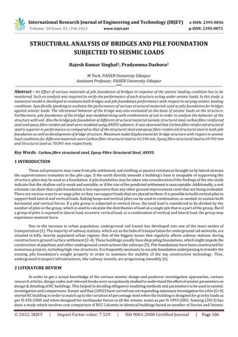
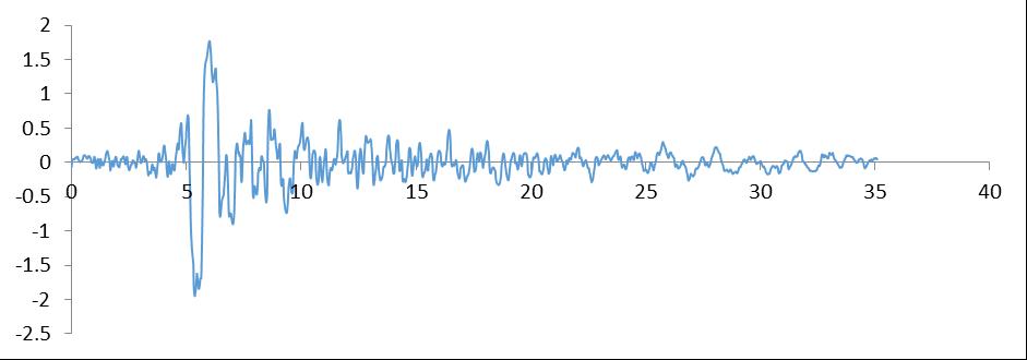
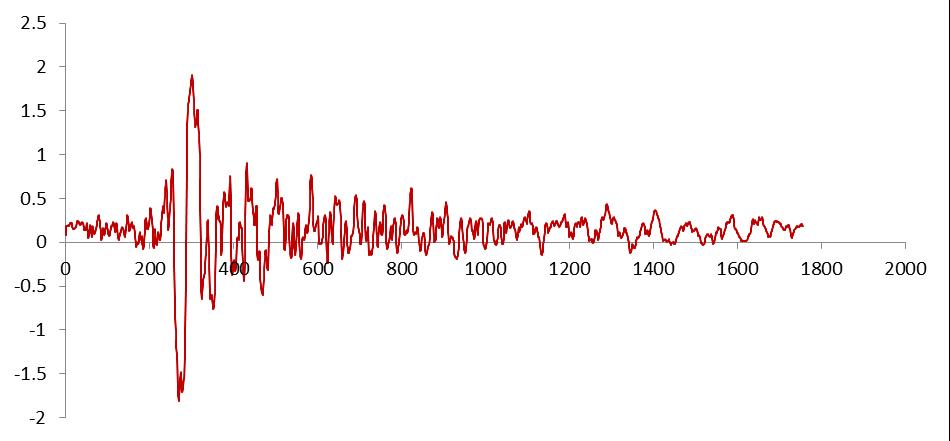
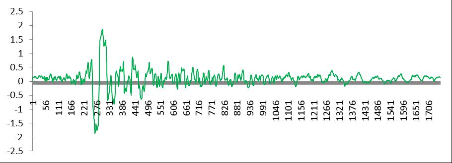
Thebridgeismodeledfirstwithseismicloadsinordertoanalyzedifferentbehaviourofthestructurewithregardsto seismic loads. The vibrational behaviour of the bridge was also evaluated on the basis of seismic loads on the structure. Furthermore,pilefoundationofthebridgewasmodeledalongwithcombinationofsoilinordertoanalyzethebehaviourofthe structure with soil. Also the bridge pile foundation of different structural material namely structural steel, carbon fibre reinforced steel and epoxy fibre reinforced steel were modeled using ANSYS software. Different bridge structures were individuallysubjectedtostrongandtypicalearthquakes,orseismicstresses,fromvariouszonesinIndia.Seismicloadsof variouszonesweretabulated,alongwithagraphoftheirtime-acceleration.Suchvaluesservedastheboundaryconditionsfor theloadingconditionsappliedtothestructureusedintherelevantstudy.Itwasnotedthatseismicresearchwascarriedout withtheunderstandingthatthebuilding'sfootwassecurelyplantedinthegroundandthatitsterminalconnectionswere fastened.Theseismicinvestigationofthebuildingrevealedthatgravityloadsalsohadasignificantimpact.
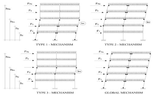
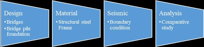
Figure4.1showsthemorphologyofthedesignthatisitrepresentsthemethodologyoftheprojectitwaseventually observedthatthebeginningandthemostimportantstepofanalysisofanybridgeismodelingofthebridgewithitscrosssectional frame and piles. In this stage it was realized that three different forms or shapes of bridge pile structure were presentedintheworkItwasobservedthatthecolumnsizeisof0.35mx0.45m,andthebeamsizeis0.23mx0.45m.material tobeusedwaspresentedintheformof:
UnitweightofRCC: 25kN/m3
UnitweightofMasonry: 20kN/m3 (Assumed)
Modulusofelasticity,ofconcrete:5000
Poisson'sratio: 0.17
Thedepthoffoundationis2mandtheheightofbridgeis5m.
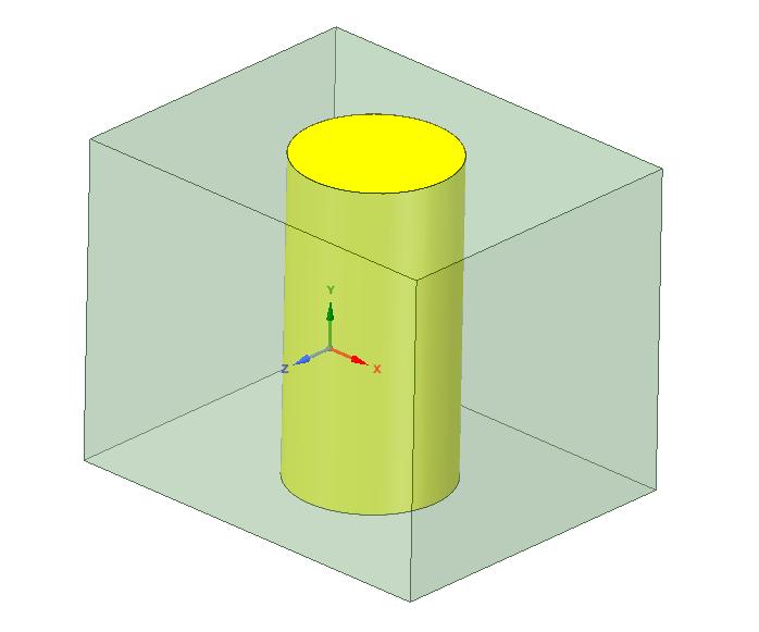
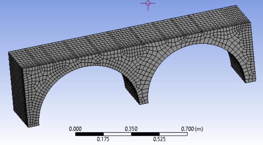
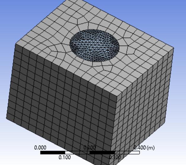
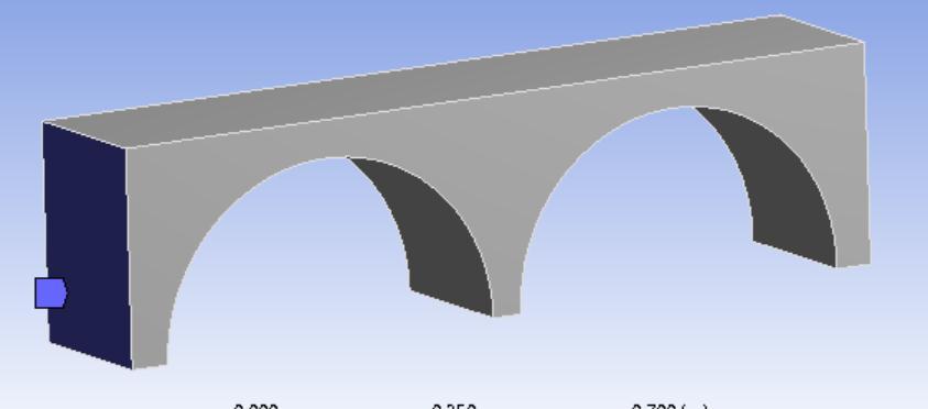
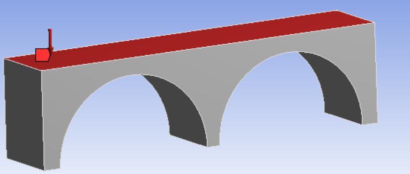
Figure4.8showsaboundaryandloadingconditionofbridgestructurewhichwasalsosubjectedtoseismicloadsin ordertoanalyzetheperformanceofsuchastructureundersuchvaryingandconditionalloadconditions.Thebridgestructure wasmadeupofstructuralsteel.
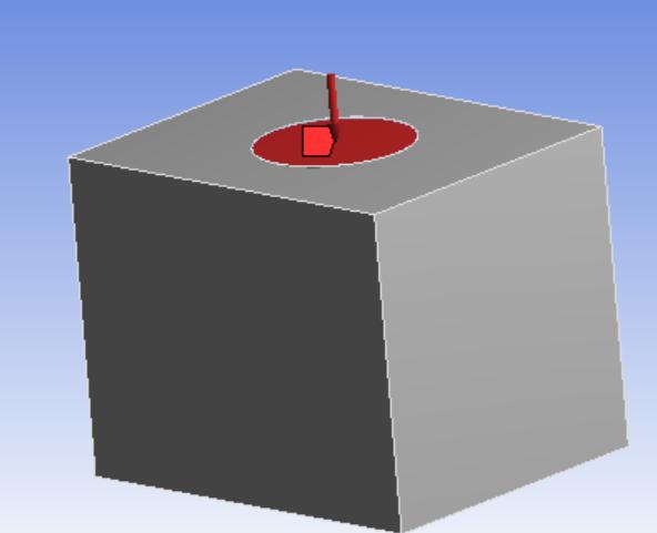
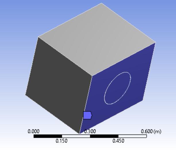
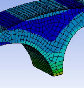
Figure4.9showsaloadingconditionofpilewithinteractionofthesoilwhichwasalsosubjectedtoseismicloadsin ordertoanalysestheperformanceofsuchastructureandalsotoevaluatehowtheinteractionbetweenthesoilandpileusually happensatthetimeofloadingandvaryingconditions.Furthermore,pileismadeupofdifferentstructurelikestructuralsteel, carbonfibrereinforcedsteelandepoxyfibrereinforcedsteel.
4.1 Boundary Conditions
Oneofthemostimportantwaystopre-processasimulationtaskistoprovideboundaryconditions.The framesystemboundaryconditionsassumedthebaseofthecolumntobefixed.Adhesivecontactwasprovided betweenallfacesoftheframepillarsthatwerejoinedtogether.Separationbetweenthejointsofthestructureisnot allowedsothattheloadisfullytransmittedthroughoutthestructure.Agravityloadwasappliedtothestructureto accountfortheeffectsofbuildinginertiaandgravityduringtheseismicanalysis.Seismicanalysiswasperformedas anexplicitdynamicanalysis.Buildingframeloadswereprovidedintheformoftimeaccelerationhistoryplotsfor differentseismiczones.
5 RESULTS AND DISCUSSION
Bridgestructureandpilefoundationwithsoilweresubjectedtoseismicloadingconditions.Bridgestructureandpile foundationwithsoilarethetwodifferentconditionsofthestructureswhichweresubjectedtohighdynamicseismicloads. Seismicloadsappliedwerealsovariedinthestructurewiththeaidoftimeaccelerationgraphobtainedfromthehistoryof differentzonesofearthquakeinIndia.
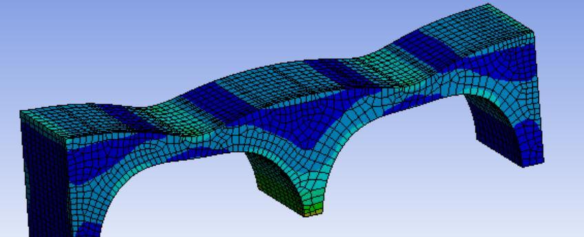
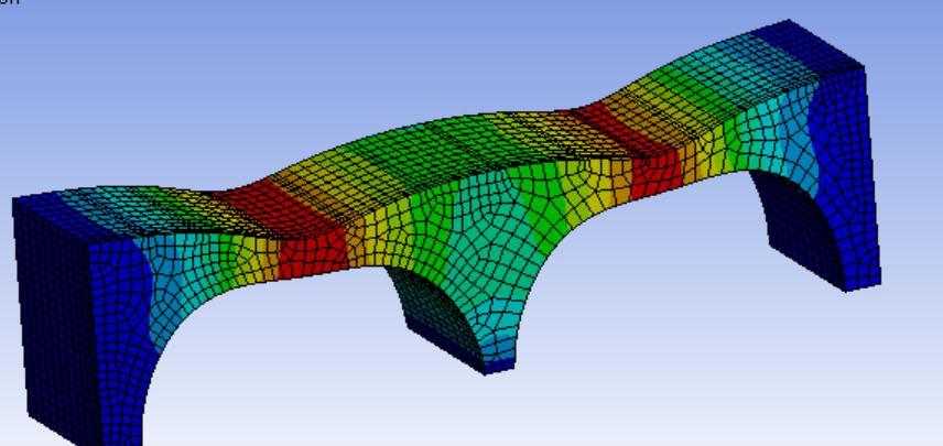
5.1 Modes of Deformation of Bridge Structure
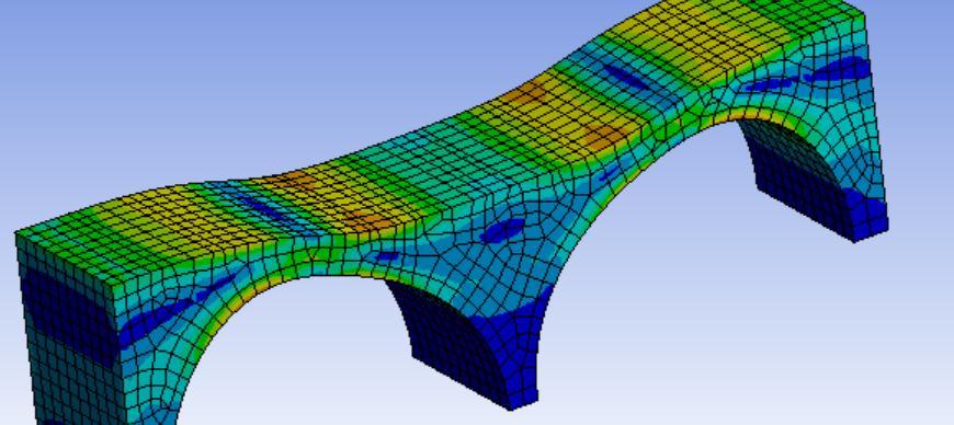
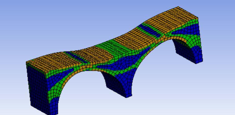
Itwas observedthatbridgesstarttobehaveverynonlinearlyundertheinfluenceofverydynamicseismic loads. Structuralnonlinearityoccursintallbridgesregardlessoftheshapeofthebuilding.Incaseofseismicloadingofthestructure resultingfromdifferentearthquakezones,thenon-linearityofthestructureremainsalmostthesame,onlythesizeofthe deformationvaries.
Itwasobservedthatforbridgestructurewithstructuralsteelseismicanalysishastobeperformedbydynamicmodes thenonlyaccurateresultswerepossible.Figure5.2showsthemodesofdeformationofthestructurewhensubjectedtohighly unstableseismicloads.Itwasobservedthatstructureundergoesatoandfromotioninthehorizontaldirectionwithtimewhile themagnitudeofthedisplacementwasdirectlyproportionaltotheintensityoftheearthquake.Itwasclearlyvisiblethatthe structure(ofanyshape)hashigherdeformationinbridgestructurewithstructuralsteelascomparedtobridgestructurewith conventionalstructuralsteel.
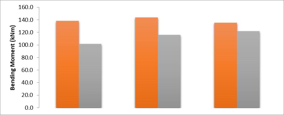
5.2 Bending Moment
WhenthemagnitudeoftheseismicloadsappliedwereasperthatoftimeaccelerationgraphofZoneIII.Allthree differenttypesofthebridgestructurenormalstructuralsteel,carbonfibresteelandepoxyfibrestructuralsteelbridgeswere subjectedtosameearthquakeloadasperZoneIIIaccordingtoIScodes.Itwasevidentthatstructuralsteelbridgeframetends tohavemaximumbendingmomentoncomparisontoothertwotypesofstructure.
III
5.3 Shear Forces in Seismic Loads
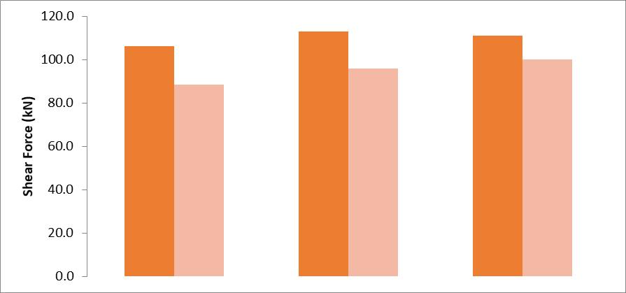
WhenthemagnitudeoftheseismicloadsappliedwereasperthatoftimeaccelerationgraphofzoneIII.Allthree differenttypesofthebridgestructurenormalstructuralsteel,carbonfibresteelandepoxyfibrestructuralsteelbridgeswas subjectedtosameearthquakeloadasperzoneIIIaccordingtoIScodes.Itwasevidentthatstructuralsteeltendstohave maximumshearforceoncomparisontoothertwotypesofstructure.
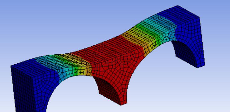
5.4 Displacement in Bridges When Subjected To Seismic Loads
WhenthemagnitudeoftheseismicloadsappliedwereasperthatoftimeaccelerationgraphofzoneIII.All threedifferenttypesofthestructurebridgestructurenormalstructuralsteel,carbonfibresteelandepoxyfiber structuralsteelbridgesassubjectedtosameearthquakeloadasperzoneIIIaccordingtoIScodes.Itwasevident thatstructuralsteeltendstohavemaximumdisplacementoncomparisontoothertwotypesofstructure.
Table1Nodaldisplacementinxdirection
MAXIMUM NODAL DISPLACEMENT (mm) IN ZONE III
Table2Nodaldisplacementinzdirection
MAXIMUM NODAL DISPLACEMENT (mm) IN ZONE III
ItwasobservedfromTable5.1.and5.2thatthemaximumdisplacementofthestructuralsteelframetendstohavethe largestnodaldisplacementinboththexandzdirectionscomparedtotheothertwostructuraltypes.Thestructuralsteelframe thereforebeginstobehave moreunstablewhen exposedtohighdynamicseismic loads,whiletheothertwoframetypes remainmorestable.
FactorofSafetyofthestructuralsteelbridgestructurewasfoundouttobeminimumof2.1whichwillbeconsideredat thesituationoftheseismicload.Furthermore,thecarbonfibrereinforcedsteelstructureandepoxyfibrereinforcedsteel structurewillhavefactorofsafetyof3.8and3.1respectively.Figure5.7showsthefactorofsafetypatternofthestructural steelstructurewithrespecttoseismicloads.
5.5 Design of Pile Foundation with Soil
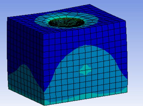
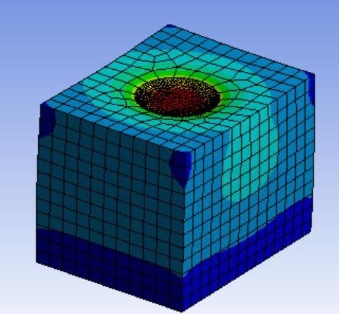
Inthiscase,thedesignofpilefoundationusedinthebridgehasbeenseparatelyanalyzedinordercharacterizethe behaviourofthepilefoundationwithsoilundertheactionofseismicloads.Thesoilmodelwasmodeledwiththeformofa cuboidalboxof1mx1mx1mandthepilefoundationrodof1mlengthand350mmdiameter.Thepilewascharacterizedwith differentmaterials.Loadingconditionofpilewithinteractionofthesoilwhichwasalsosubjectedtoseismicloadsinorderto analyses the performance of such a structure and also to evaluate how the interaction between the soil and pile usually happensatthetimeofloadingandvaryingconditions.Furthermore,pileismadeupofdifferentstructurelikestructuralsteel, carbonfibrereinforcedsteelandepoxyfibrereinforcedsteel.
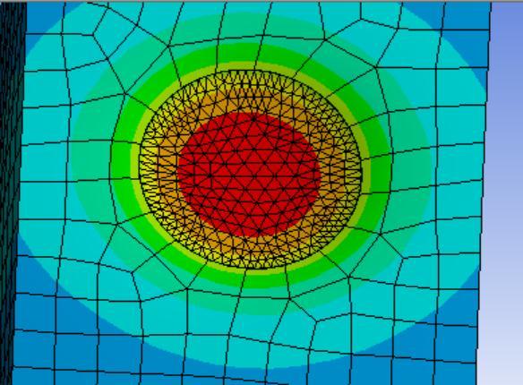
23VariationbetweenCarbonfibrereinforcedsteelpileandstructuralsteelpiledesign
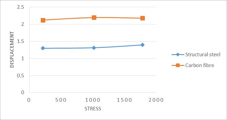
Itisclearlyevidentfromthefigure5.11thatthestructurefoundationofpileswithrespecttothedifferentmaterials performsindifferentforms.Itwasobservedthatthepilefoundationmadeupofcarbonfibremixedstructuralsteelperformed muchbetterascomparedtothatoftheconventionalstructuralsteel.
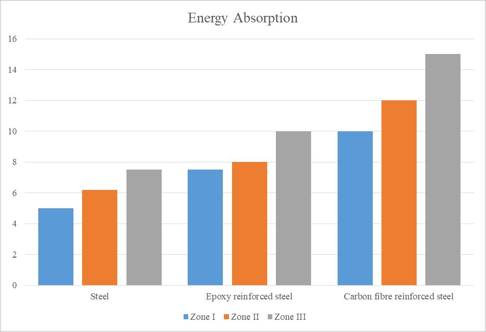
Itisclearlyevidentfromthefigure5.12thatthestructurefoundationofpileswithrespecttothedifferentmaterials performsindifferentforms.Itwasobservedthatthepilefoundationmadeupofcarbonfibremixedstructuralsteelperformed muchbetterascomparedtothatoftheconventionalstructuralsteelandthatofepoxyfibrereinforcedsteel.Thestructures weresubjectedtodifferentformsofloadingconditionswithrespecttodifferentseismicloadingconditions.Energyabsorption characteristicsandmaximumdeformationcharacteristicsofthestructurewasperformedandcomparedtoeachotherunder
variableloadingconditionstoestimatetheperformanceofthestructure.ItwasobservedthattheenergyabsorbedbyCarbon fibrereinforcedstructuralsteelabsorbsthemaximumamountandenergyandundergoeslessdeformation.Therefore,Carbon fibre reinforced structural steel is superior in performance as compared to that of the structural steel and epoxy fibre reinforcedstructuralsteel.
6 CONCLUSION
Theeffectivenessofpilingfoundationsforbridgesagainstseismicloadshaslongbeenasignificantissue.Designofthe bridgesunderearthquakeisimpededbyalackofinterpretationandknowledgeofthecharacteristicsaffectingtheperformance of bridge foundation structures under seismic loading. The creation of a numerical model that can accurately depict the earthquakephenomenonanddosoatalowcostwhilesimulatingsituationsthatreal-worldbuildingswouldexperienceis crucial. Even though dynamic analysis is a laborious and time-consuming endeavor, practicality becomes crucial for a structure'sperformance andevaluationatits best.Itis necessarytoconsiderhow different pilefoundation materialsfor bridgesrespondtoseismicloadingconditionsweremonitored.Suchananalysiswasrequiredtoverifytheperformanceofeach structureactingunderseismicloads.Inthisstudy,anumericalmodelisdevelopedtoevaluatebothbridgesandpilefoundation performancewithrespecttovaryingseismicloadingconditions.
Carbonfibrereinforcedstructuralsteelissuperiorinperformanceascomparedtothatofthestructuralsteeland epoxyfibrereinforcedstructuralsteelinbothpilefoundationaswellasdevelopmentofbridgestructure.
Carbon fibrestructural steel pilefoundationundergoesa maximumdisplacementof 9mm,13.5 mmand 21mm respectivelyinZoneIII,ZoneIVandZoneV.
Epoxyfibrestructuralsteelpilefoundationundergoesamaximumdisplacementof8.5mm,12mmand18.5mm respectivelyinZoneIII,ZoneIVandZoneV.
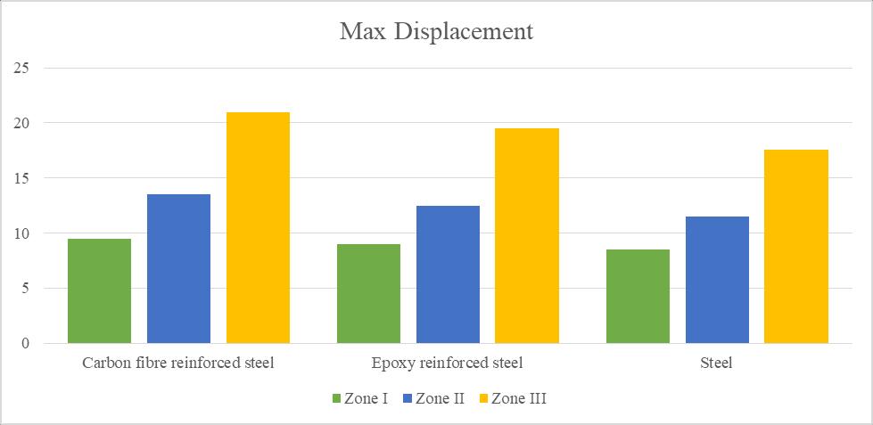
Structuralsteelpilefoundationundergoesamaximumdisplacementof7.5mm,11mmand17mmrespectivelyin ZoneIII,ZoneIVandZoneV.
FactorofSafetyofthestructuralsteelbridgestructurewasfoundouttobeminimumof2.1whichwillbeconsidered atthesituationoftheseismicload.Furthermore,thecarbonfibrereinforcedsteelstructureandepoxyfibrereinforced steelstructurewillhavefactorofsafetyof3.8and3.1.
Maximumnodaldisplacementforbridgestructurewithrespecttoseismicloadconditionsfordifferentmaterialswere Carbonfibrestructuralsteelas63.104mm,EpoxyFibrestructuralsteelas69.992mmandStructuralsteelas70.091 mmrespectively.
7 REFERENCES
1. Luan,X.,Cheng,L.,Song,Y.,&Zhao,J.(2020).Betterunderstandingthechoiceoftravelmodebyurbanresidents:New insightsfromthecatchmentareasofrailtransitstations.Sustainablecitiesandsociety,53,101968.
2. Su,Z.,&Li,X.(2020).Sub-systemenergymodelbasedonactualoperationdataforsubwaystations.SustainableCities andSociety,52,101835.
3. Wang, Z. Z., & Chen, C. (2017). Fuzzy comprehensive Bayesian network-based safety risk assessment for metro constructionprojects.TunnellingandUndergroundSpaceTechnology,70,330-342.
4. Ding, L. Y., Yu, H. L., Li, H., Zhou, C., Wu, X. G., & Yu, M. H. (2012). Safety risk identification system for metro constructiononthebasisofconstructiondrawings.Automationinconstruction,27,120-137.
5. Guo, X., Wang, Z., Geng, P., Chen, C., & Zhang, J. (2021). Ground surface settlement response to subway station constructionactivitiesusingpile–beam–archmethod.TunnellingandUndergroundSpaceTechnology,108,103729.
6. Li, Z., Chen, Z., Wang, L., Zeng, Z., & Gu, D. (2021). Numerical simulation and analysis of the pile underpinning technologyusedinshieldtunnelcrossingsonbridgepilefoundations.UndergroundSpace,6(4),396-408.
7. Guner,S.,&Chiluwal,S.(2021).Cyclicloadbehaviorofhelicalpile-to-pilecapconnectionssubjectedtoupliftloads. EngineeringStructures,243,112667.
8. Lu,M.M.,Xie,K.H.,Wang,S.Y.,&Li,C.X.(2013).Analyticalsolutionfortheconsolidationofacompositefoundation reinforcedbyanimperviouscolumnwithanarbitrarystressincrement.InternationalJournalofGeomechanics,13(1), 33-40.
9. Kim,H.J.,Mission,J.L.,Park,T.W.,&Dinoy,P.R.(2018).Analysisofnegativeskin-frictiononsinglepilesbyonedimensionalconsolidationmodeltest.InternationalJournalofCivilEngineering,16(10),1445-1461.
10. Li,B.,Yu,J.,Zhou,Y.,Cai,Y.,Liu,S.,&Tu,B.(2021).Acomputationmodelforpile-soilstressratioofgeosyntheticreinforced pile-supported embankments based on soil consolidation settlement. Alexandria Engineering Journal, 60(1),39-48.
11. Zhuang,Y.,&Wang,K.(2017).Analyticalsolutionforreinforcedpiledembankmentsonelastoplasticconsolidatedsoil. InternationalJournalofGeomechanics,17(9),06017010.
12. Chen,R.P.,Zhou,W.H.,&Chen,Y.M.(2009).Influencesofsoilconsolidationandpileloadonthedevelopmentof negativeskinfrictionofapile.ComputersandGeotechnics,36(8),1265-1271.
13. Li,B.,&Wang,Z.Z.(2019).Numericalstudyontheresponseofgroundmovementstoconstructionactivitiesofa metrostationusingthepile-beam-archmethod.TunnellingandUndergroundSpaceTechnology,88,209-220.
14. Liu,X.,Liu,Y.,Yang,Z.,&He,C.(2017).Numericalanalysisonthemechanicalperformanceofsupportingstructures andgroundsettlementcharacteristicsinconstructionprocessofsubwaystationbuiltbyPile-Beam-Archmethod. KSCEJournalofCivilEngineering,21(5),1690-1705.
15. Thongmunee,S.,Matsumoto,T.,Kobayashi,S.I.,Kitiyodom,P.,&Kurosawa,K.(2011).Experimentalandnumerical studiesonpush-uploadtestsforsandplugsinasteelpipepile.Soilsandfoundations,51(5),959-974.
16. Khoubani, A., & Evans, T. M. (2018). An efficient flexible membrane boundary condition for DEM simulation of axisymmetricelementtests.InternationalJournalforNumericalandAnalyticalMethodsinGeomechanics,42(4),694715.
17. Shire, T., Hanley, K. J., & Stratford, K. (2020). DEM simulations of polydisperse media: efficient contact detection appliedtoinvestigatethequasi-staticlimit.ComputationalParticleMechanics,1-11.
18. Sloan, S. W., & Randolph, M. F. (1982). Numerical prediction of collapse loads using finite element methods. InternationalJournalforNumericalandAnalyticalMethodsinGeomechanics,6(1),47-76.
19. Dijkstra, J., Broere, W., Bezuijen, A., & Van Tol, A. F. (2008). 44 DENSITY CHANGES NEAR AN ADVANCING DISPLACEMENTPILEINSAND.
20. Xu,Q.,Zhu,H.,Ma,X.,Ma,Z.,Li,X.,Tang,Z.,&Zhuo,K.(2015).Acasehistoryofshieldtunnelcrossingthroughgroup pilefoundationofaroadbridgewithpileunderpinningtechnologiesinShanghai.TunnellingandUndergroundSpace Technology,45,20-33.
21. Park, Y. H., Kim, J. P., & Cho, K. H. (2015). Stability analysis of subway box structure supported by modified underpinningmethod.TunnellingandUndergroundSpaceTechnology,50,199-208.
22. ZHANG, W. Q. (2006). Analysis on Settlement of Pile Foundation Underpinning Area Induced by Construction of OverlappedTunnels[J].TunnelConstruction,1.
23. Tao,D.,Zhen-chang,G.,Kai-liang,C.,&Li-yong,L.(2015).Simplifiedcalculationofjackingloadinactiveunderpinning ofbridgepiles.RockandSoilMechanics,36(11),3259-3267.
24. Li, Z., Chen, Z., Wang, L., Zeng, Z., & Gu, D. (2021). Numerical simulation and analysis of the pile underpinning technologyusedinshieldtunnelcrossingsonbridgepilefoundations.UndergroundSpace,6(4),396-408.
25. Yu,Y.,Richardson,D.C.,&Michel,P.(2017).Structuralanalysisofrubble-pileasteroidsappliedtocollisionalevolution. Astrodynamics,1(1),57-69.
26. Poulos,H.G.(1976).Behaviouroflaterallyloadedpilesnearacutorslope.
27. Schmidt,H.G.(1977).Largediameterboredpilesforabutments.Proc.,SpecialtySessionontheEffectofHorizontal LoadsonPiles,9thICSMFE,Tokyo,1977,107-112.
28. Bouafia,A.,&Bouguerra,A.(1996).Centrifugetestingofthebehaviourofahorizontallyloadedflexiblepileneartoa slope.InInternationalJournalofRockMechanicsandMiningSciencesandGeomechanicsAbstracts(Vol.3,No.33,p. 135A).
29. Mezazigh, S., & Levacher, D. (1998). Laterally loaded piles in sand: slope effect on py reaction curves. Canadian GeotechnicalJournal,35(3),433-441.
30. Chen,C.Y.,&Martin,G.R.(2020).Effectofembankmentslopeonlateralresponseofpiles.InFLACandnumerical modelinginGeomechanics(pp.205-213).CRCPress.
31. Chae,K.S.,Ugai,K.,&Wakai,A.(2004).Lateralresistanceofshortsinglepilesandpilegroupslocatednearslopes. InternationalJournalofGeomechanics,4(2),93-103.
32. Georgiadis,K.,&Georgiadis,M.(2010).Undrainedlateralpileresponseinslopingground.Journalofgeotechnicaland geoenvironmentalengineering,136(11),1489-1500.
33. Moayed, R. Z., Kamalzare, M., & Judi, A. (2013). Three-dimensional analyses of concrete piles in clayey soils. ProceedingsoftheInstitutionofCivilEngineers-GeotechnicalEngineering,166(4),399-407.
34. Ziaie-Moay,R.,Kamalzare, M.,&Safavian, M.(2010).Evaluationof piled raft foundations behavior withdifferent dimensionsofpiles.JournalofAppliedSciences,10(13),1320-1325.
35. Jesmani,M.,Kasrania,A.,Kamalzare,M.,&Mehdipour,I.(2015).Undrainedverticalbearingcapacityofpilelocated nearsoftclayslope.JournalofEngineeringResearch,3(3),21-38.
36. Horikoshi, K., Matsumoto, T., Hashizume, Y., Watanabe, T., & Fukuyama, H. (2003). Performance of piled raft foundationssubjectedtostatichorizontalloads.InternationalJournalofPhysicalModellinginGeotechnics,3(2),3750.
37. Lee,S.H.,&Chung,C.K.(2005).Anexperimentalstudyoftheinteractionofverticallyloadedpilegroupsin sand. CanadianGeotechnicalJournal,42(5),1485-1493.
38. Cao, X. D., Wong, I. H., & Chang, M. F. (2004). Behavior of model rafts resting on pile-reinforced sand. Journal of geotechnicalandgeoenvironmentalengineering,130(2),129-138.
39. Matsumoto,T.,Nemoto,H.,Mikami,H.,Yaegashi,K.,Arai,T.,&Kitiyodom,P.(2010).Loadtestsofpiledraftmodels withdifferentpileheadconnectionconditionsandtheiranalyses.SoilsandFoundations,50(1),63-81.
40. Ata, A., Badrawi, E., & Nabil, M. (2015). Numerical analysis of unconnected piled raft with cushion. Ain Shams EngineeringJournal,6(2),421-428.
41. ElSawwaf,M.(2010).Experimentalstudyofeccentricallyloadedraftwithconnectedandunconnectedshortpiles. Journalofgeotechnicalandgeoenvironmentalengineering,136(10),1394-1402.
42. SaeediAzizkandi,A.,Baziar,M.H.,Rasouli,H.,Modarresi,M.,&Shahnazari,H.(2015).Centrifugemodelingofnonconnectedpiledraftsystem.InternationalJournalofCivilEngineering,13(2),114-123.
43. Fioravante,V.(2011).Loadtransferfromarafttoapilewithaninterposedlayer.Géotechnique,61(2),121-132.
44. ElKamash,W.,ElNaggar,H.,Nabil,M.,&Ata,A.(2020).Optimizingtheunconnectedpiledraftfoundationforsoftclay soils:NumericalStudy.KSCEJournalofCivilEngineering,24(4),1095-1102.
45. Chang-Yu, O., Shiau, B. Y., & Wang, I. W. (2000). Three-dimensional deformation behavior of the Taipei National EnterpriseCenter(TNEC)excavationcasehistory.CanadianGeotechnicalJournal,37(2),438.
46. Liu,L.,Wu,R.,Congress,S.S.C.,Du,Q.,Cai,G.,&Li,Z.(2021).Designoptimizationofthesoilnailwall-retainingpileanchorcablesupportingsysteminalarge-scaledeepfoundationpit.ActaGeotechnica,1-24.
47. Wang,H.L.,&Chen,R.P.(2019).Estimatingstaticanddynamicstressesingeosynthetic-reinforcedpile-supported track-bedundertrainmovingloads.JournalofGeotechnicalandGeoenvironmentalEngineering,145(7),04019029.
48. Zhang,Q.Q.,Liu,S.W.,Feng,R.F.,Qian,J.G.,&Cui,C.Y.(2020).Finiteelementpredictionontheresponseofnonuniformlyarrangedpilegroupsconsideringprogressivefailureofpile-soilsystem.FrontiersofStructuralandCivil Engineering,14(4),961-982.
49. Finn, W.D.L.,&Fujita,N.(2002).Pilesinliquefiablesoils: seismic analysisanddesignissues.Soil Dynamicsand EarthquakeEngineering,22(9-12),731-742.
50. Cheng, Z., & Jeremić, B. (2009). Numerical modeling and simulation of pile in liquefiable soil. Soil Dynamics and EarthquakeEngineering,29(11-12),1405-1416.
51. Lu,J.,Elgamal,A.,Yan,L.,Law,K.H.,&Conte,J.P.(2011).Large-scalenumericalmodelingingeotechnicalearthquake engineering.InternationalJournalofGeomechanics,11(6),490-503.
52. Chang,D.,Boulanger,R.,Brandenberg,S.,&Kutter,B.(2013).FEManalysisofdynamicsoil-pile-structureinteractionin liquefiedandlaterallyspreadingground.EarthquakeSpectra,29(3),733-755.
53. Dafalias,Y.F.,&Manzari,M.T.(2004).Simpleplasticitysandmodelaccountingforfabricchangeeffects.Journalof Engineeringmechanics,130(6),622-634.
54. Wang,R.,Zhang,J.M.,&Wang,G.(2014).Aunifiedplasticitymodelforlargepost-liquefactionsheardeformationof sand.ComputersandGeotechnics,59,54-66.
55. Wang,R.(2016).Aunifiedplasticitymodelforlargepost-liquefactionsheardeformationofsandanditsnumerical implementation.InSinglePilesinLiquefiableGround(pp.25-53).Springer,Berlin,Heidelberg.
56. Oh,E.,Bui,Q.M.,Surarak,C.,Adamec,R.,&Balasubramaniam,B.(2008).Parametricstudyonpiledraftfoundationin sandusingnumericalmodelling.FuturMechStructMater,261.
57. Baziar,M.H.,Ghorbani,A.,&Katzenbach,R.(2009).Small-scalemodeltestandthree-dimensionalanalysisofpile-raft foundationonmedium-densesand.
58. Long, P. D., & Vietnam, V. W. (2010). Piled raft a cost-effective foundation method for high-rises. Geotechnical Engineering,41(1),149.
59. Al-Mosawi,M.J.,Fattah,M.Y.,&Al-Zayadi,A.A.(2011).Experimentalobservationsonthebehaviorofapiledraft foundation.JournalofEngineering,17(4),1-11.
60. El-Garhy,B.,Galil,A.A.,Youssef,A.F.,&Raia,M.A.(2013).Behaviorofraftonsettlementreducingpiles:Experimental modelstudy.JournalofRockMechanicsandGeotechnicalEngineering,5(5),389-399.
61. Park,D.,&Lee,J.(2015).Comparativeanalysisofvariousinteractioneffectsforpiledraftsinsandsusingcentrifuge tests.JournalofGeotechnicalandGeoenvironmentalEngineering,141(1),04014082.