Thermal Analysis and Design Optimization of Solar Chimney using CFD
Ajay Singh 1, Purushottam Sahu2, Ghanshyam Dhanera 3
1 Research Scholar, BM College of Technology, Indore

2Professor and HEAD, BM College of Technology, Indore
3Example: 2AssistantProfessor, BM College of Technology, Indore, MP ***
Abstract:
The solar chimney design is modeled using 3D parametric Creo design software and CFD analysis is conducted using ANSYSsimulationpackage.Thecomparativeanalysisiscomparedbetweenstraightcollectordesignandstaggereddesign ofsolarchimneycollectoronthebasisofairflow,thermalgradientandpressuredistribution.
Keywords: Solarchimney,CFD,collectors
1. Introduction
Current power generation from fossil energies such as oil,coal, or natural gas is harmful to the atmosphere & has the drawbackofbeingnon-renewable.Manydevelopedcountriesaren'tabletotheseconventionalenergysources,&nuclear power isconsideredan unnecessary risk in some oftheseareas.Lack of electricity hasbeen linkedto poverty,&poverty has been linked to population increases. As a result, the need for an eco-friendly and expensive electricity generation systemisclear,anditwillonlybecomemoresointhefuture.Solarenergyisonepotentialsolutiontotheever-increasing crisis.
1.2Concept of Solar Chimney
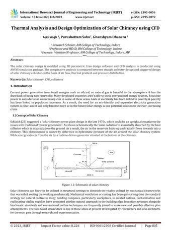
Schlaich[23]suggesteda‘solarchimneypowerplantdesigninthelate1970s,whichcouldbeanuprightalternativetothe issueswithtraditional“powergenerators”.Asshownschematicallythe‘solarradiation’isessentiallyabsorbedbytheheat collectorwhichissituatedabovetheground.Asaresult,theairinthereservoirheatsupandradiallyflowsinwardsintoa chimney. This phenomenon is causedby difference in hydrostatic pressure of the air around the solar chimney system. Whileenergyextractsfromtheairbyaturbine-drivengeneratorsituatedatthebottomofthechimney.
Solarchimneys canlikewise beutilizedinstructural settingstodiminish the vitality utilized by mechanical (frameworks thatwarmth&coolingtheworkingmechanical).Mechanicalventilationorcoolinghasbeenquitealongtimethestandard strategy for natural control in many building composes, particularly workplaces, in created nations. Contamination and reallocatingvitality supplies havepromptedanothernatural approachinthebuildingplan.Inventiveadvancesalongside bioclimaticstandardsandconventional outlinetechniquesarefrequentlyjoinedto makenewand possibly effective plan arrangements.Thesun-basedsmokestackisoneoftheseideasatpresentinvestigatedbyresearchersandalsoarchitects, forthemostpartthroughresearchandexperimentation.
2 Methodology Steps
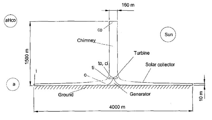
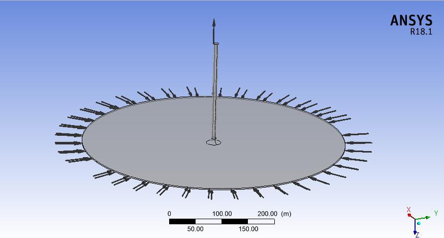
TheCADmodel of a solarchimneyismodeledasperthedimensionsavailablein theliterature[25]. Thedimensionsof a solarchimneyaregivenintable2.1below.
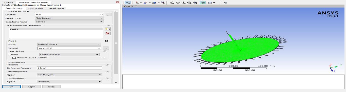
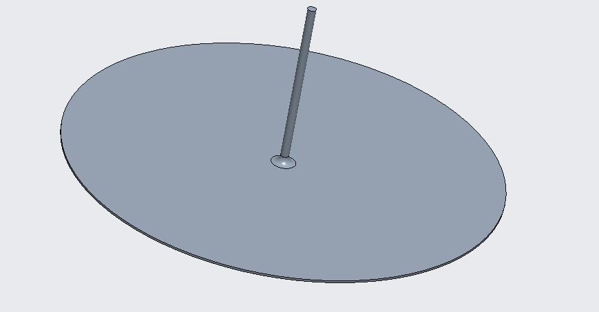
TheCADmodelsofasolarchimneyareindustrializedin(Creodesignsoftware).ThetoolusedforCADmodelingofasolar chimney is a revolving tool with material addition. Imported in ANSYS design modeler, the ‘CAD‘model created in Creo designsoftwareisimported.
TheCADmodelsindustrializedinCreoareshowninfigure5.3above.asshowninfigure5.4below.wheregeometricerrors suchashardedges,corneredges,andsoonarechecked.
LoadsandBoundaryconditions
The outlet and inlet conditions of the boundary are defined as shown in figure 5.7 above. The inlet boundary condition comprisesofdefiningairinletspeedof.05m/sandinletheattemperaturedefinitionof300Kasshowninfigure5.8below. Theoutletboundaryconditioninvolvesthesettingofrelativepressuredifferenceto0asnoexternalpumpingequipment isusedinthesimulation.
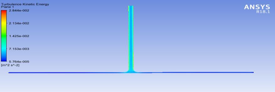
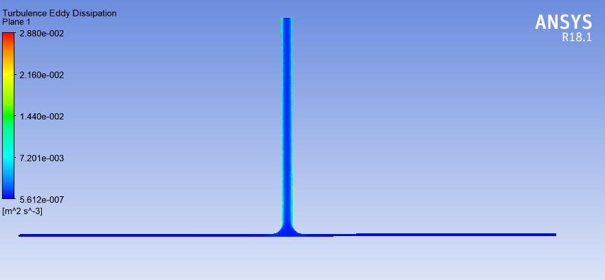
Turbulenceeddydissipationplotofflatsurfacedesignat800W/m2 heatflux
The turbulence eddy dissipation plot is shown in figure 6.10 above. The plot shows higher turbulence eddy dissipation nearthevertical chimneywith a magnitudeof.0144m2s-3.Themaximumturbulenceeddydissipationobtained from the analysis is .0288 m2s-3. Similarly, the maximum turbulence kinetic energy obtained from simulation is observed near the vicinity of a vertical zone with a magnitude of .002844 m2s-3. The minimum kinetic energy is observed underneath the collector'sface.
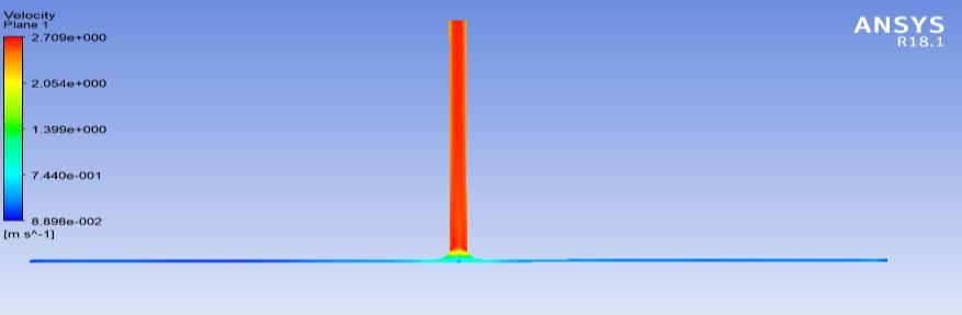
The velocity plot shows a higher magnitude in vertical members and a lower magnitude underneath the collector's face. Themagnitudeofvelocityincreasedsuddenlyatthecornerandreaches1.39m/sasshownbythegreencolor.
6.2 Staggered Surface Results
FurtherCFDanalysisisconductedonthestaggeredsurfaceofthecollectorunderthesameloadingconditions.
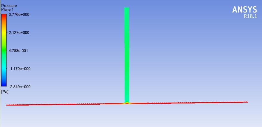
Thepressureplotgeneratedfortheflatplatecollectorsolarchimneyisshowninfigures6.13above.Theplotshowshigher pressureunderneaththecollector'sfacewithamagnitudeof3.77Paandreducesasairmovestowardstheinclinedexitof achimney.Thepressureattheverticalzoneis.47Paandthepressureatthecommoninterfaceis2.12Pa.
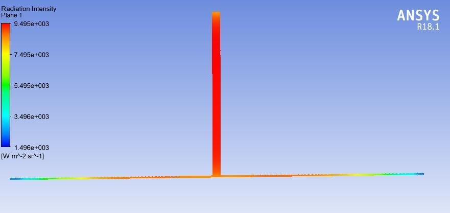
Theradiationintensityplotshowsanalmostconstantdistributionofradiationalongtheverticalzoneandunderneaththe flat collector type. The variation of radiation intensity is low and is observed to be highest at the vertical zone with a magnitudeof9495W/m2 sr-1
7.1 Conclusion
Thedetailedresultsare:
1. The pressure profile obtained along the length of the chimney is similar for both staggered design and flat collectordesign.
2. Thek-epsilonturbulencemodelgavereasonablygoodpredictionsasthefluidflowdidn’tfoundtobeturbulent.
3. Thepressuredistributionalongtheradialdirectionisdifferentforbothflatplatecollectorchimneyandstaggered designchimney.
4. For 1000W heat flux, the staggered design generated a 10.7% higher pressure drop as compared to the flat collectordesign.
REFERENCES
[1].Dimoudi,A.Solarchimneysinbuildings Thestateoftheart.Adv.Build.EnergyRes.2009,3,21–44.
[2].Khanal,R.;Lei,C.Solarchimney Apassivestrategyfornaturalventilation.EnergyBuild.2011,43,1811–1819.
[3]. Ohanessian, P.; Charters, W.W.S. Thermal simulation of a passive solar house using a Trombe-Michel wall structure. Sol.Energy1978,20,275–281.
[4].Akbarzadeh,A.;Charters,W.W.S.;Lesslie,D.A.ThermocirculationcharacteristicsofaTrombewallpassivetestcell.Sol. Energy1982,28,461–468.
[5]. Das, S.K.; Kumar, Y. Design and performance of a solar dryer with vertical collector chimney suitable for rural application.EnergyConvers.Manag.1989,29,129–135.
[6].Awbi,H.B.Designconsiderationsfornaturallyventilatedbuildings.Renew.Energy1994,5,1081–1090.
[7]. Aboulnaga, M.M. A roof solar chimney assisted by cooling cavity for natural ventilation in buildings in hot arid climates:anenergyconservationapproachinAl-Aincity.Renew.Energy1998,14,357–363.
[8].Khedari,J.;Lertsatitthanakorn,C.;Pratinthong,N.;Hirunlabh,J.ThemodifiedTrombewall:Asimpleventilationmeans andanefficientinsulatingmaterial.Int.J.AmbientEnergy1998,19,104–110.
[9].Hirunlabh,J.;Kongduang,W.;Namprakai,P.;Khedari,J.Studyofnaturalventilationofhousesbya metallicsolarwall undertropicalclimate.Renew.Energy1999,18,109–119.
[10].Afonso,C.;Oliveira,A.Solarchimneys:Simulationandexperiment.EnergyBuild.2000,32,71–79.
[11].Khedari,J.;Boonsri,B.;Hirunlabh.J.Ventilationimpactofasolarchimneyonindoortemperaturefluctuationandair changeinaschoolbuilding.EnergyBuild.2000,32,89–93.
[12].Spencer,S.;Chen,Z.D.;Li,Y.;Haghighat,F.Experimentalinvestigationofasolarchimneynaturalventilationsystem InAirDistributioninRooms,Proceedingsofthe7thInternationalRoomventConference,Reading,UK,9–12July2000;pp. 813–818.