
Performance Analysis of microstrip antenna and its array for 2.4ghz application
Sailee palekar Student, Dept. of Electronics and Telecommunication Engineering, Goa Engineering college, Goa, India
Abstract- In this Paper Performance Analysis Of Microstrip Patch Antenna at f=2.4Ghz for Wireless LAN Application is studied and results are analyzed using HFSS v15 software. The FR4 epoxy with relative permittivity 4.4 is used as substrate material. Our goal here is to obtain high gain and reduced losses, to be especially used for WLAN applications. Using an array 1*3 rectangular patch we obtain gain of 7.1dB and return loss of -10.3dB.
Key words - WLAN, Microstrip Patch, HFSS, Gain, Return Loss
1. INTRODUCTION
Today wireless communication has become more of a direnecessityinvariousapplications.Inmanyscenarios where the wired systems are impractical or almost impossible to be implemented, wireless systems have readily replaced them. Many systems are actually required to actually transmit a message and receive it with minimal error in a wireless systems. Such blocks like transmitter, receiver, coders etc. are required to pass information both over short and long distances. Taketheexampleoftheunlicensedspectrumof2.4 GHz for interconnecting Wi-Fi devices such as connecting laptops or mobile devices for people in transit. This spectrum in small range is used for communicating multipledevicesinvariousnetworkstherebygenerating requirement of various kinds of specialised antenna for thesuitablepurpose.Onemoreuseforwirelesssystems isonethatconnectthemobilenetworktoconnecttothe satellites. Take the example of GPS systems where devices need to be within the range of three or more satellites. The location is transmitted from the satellites in range via the communicating channels. Sopracticallytheantennaneedstobedesignedinsucha manner that the signals can be detected in any orientation. So a circularly polarised antenna is the requirement for such an application which overcomes the orientation problem. In this Paper Performance Analysis Of Microstrip Patch Antenna at f=2.4Ghz for Wireless LAN Application is studied and results are analyzed using HFSS v15 software. The FR4 epoxy with relativepermittivity4.4isusedassubstrate material.
2. Theory And Methodology
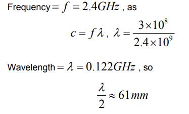
For simplified analysis and better performance of the WLAN Systems, a rectangular-shaped microstrip patch antenna operating at 2.4 GHz has been proposed. While designinganarray,themostimportantparameterwhich must be accommodate very carefully is adjustment of distance between the radiating elements of an array in ordertokeepitcompactaswellasefficient
Inourproposedwork:
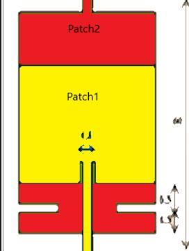
It’sthesandwichofthetwopatcheswithgroundplanein betweenasshowninfigureabove.
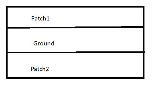
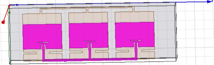
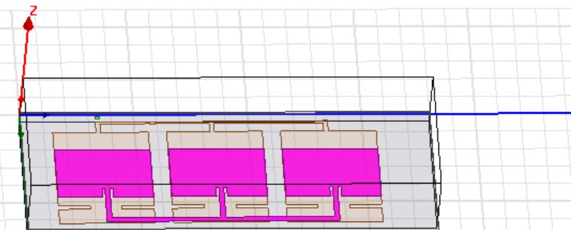
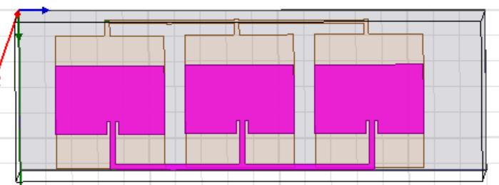
Itconsistsoftworectangularpatchesplacedsidebyside with an overall dimension of 60mm x 130mm x 1.5 mm to give directive radiation pattern and maximum gain. Each element has individual ground plane to make furtherseparationamongthemandisfedindependently by transmission line with an impedance matching of 50 Ω. The distance between both the transmission lines is 60mm approximately equal to the one calculated mathematically. The distance between radiating elementssetis18mmandisadjustedinsuchawaythat the operational frequency remains at 2.4 GHz with improveddirectivityandgain
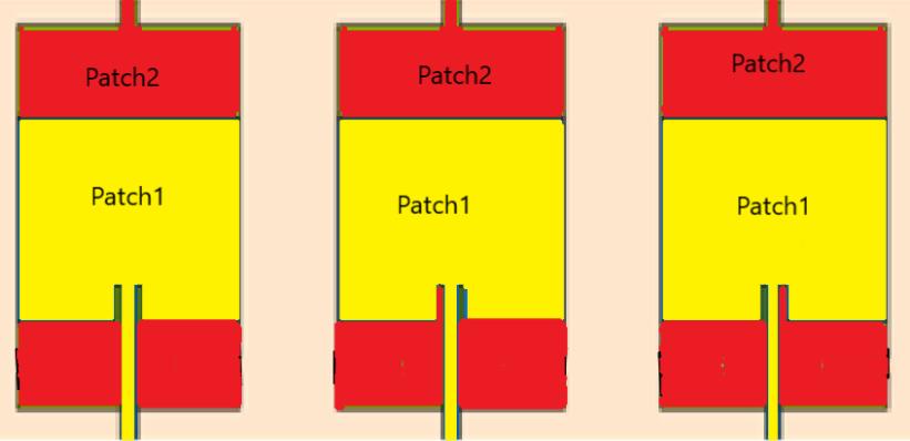
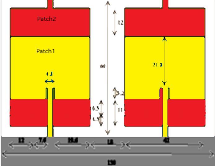
Toenhancethegainanddirectivityobtainedfrom single element,a linear triplearrayof162mm*60mm*1.5mm wassimulatedinHFSS.
3. Design Specification
The parameters that have been used in this proposed rectangularmicrostrippatchantennaaregivenbelow:
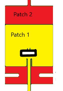
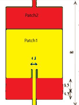
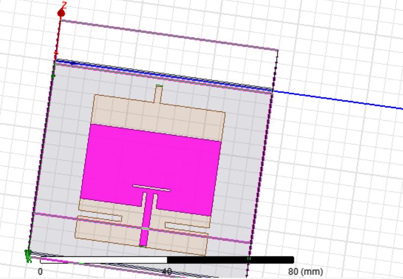
Fig-9:1*1RectangularPatchwithoutSlots Table-1:DimensionsofSlotinPatch2
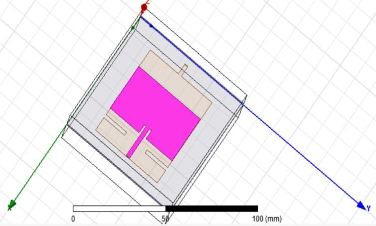
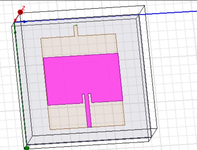
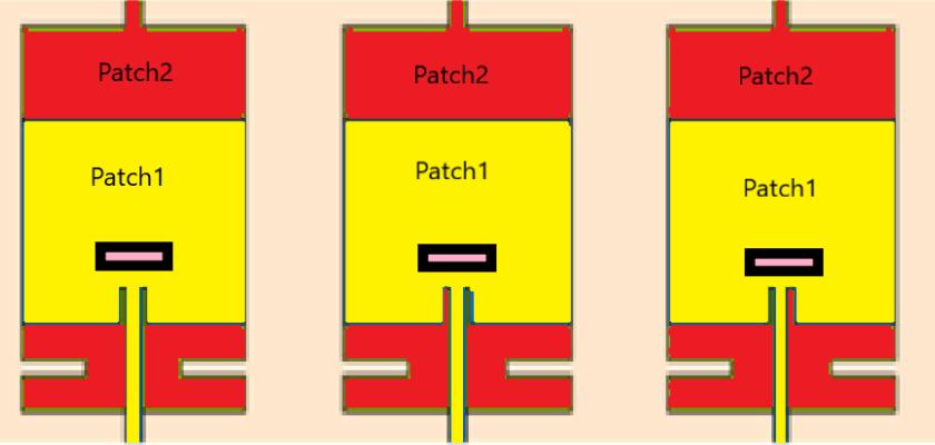
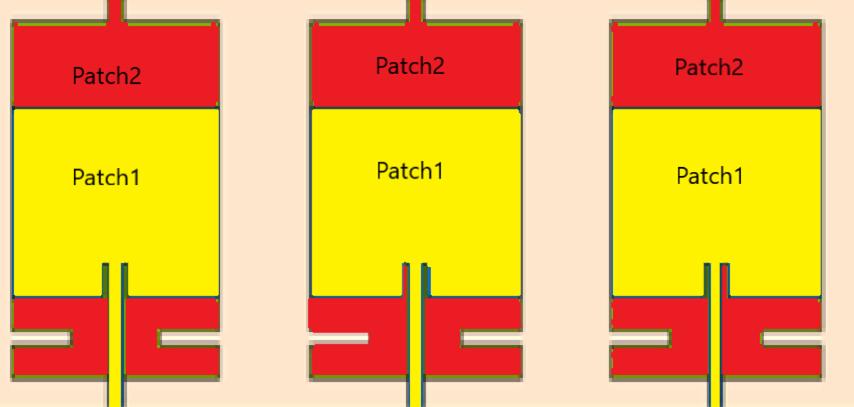
Fig-10:1*1RectangularPatchwithSlots
Table-2:DimensionsofSlotinPatch1
All the simulation results of the implemented rectangularmicrostrippatchantennaforWLANSystems have been successfully carried out. Simulations includes
the Return Loss, Voltage Standing Wave Ratio (VSWR), DirectivityandGain.
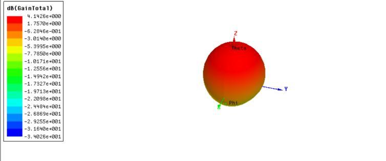
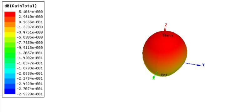
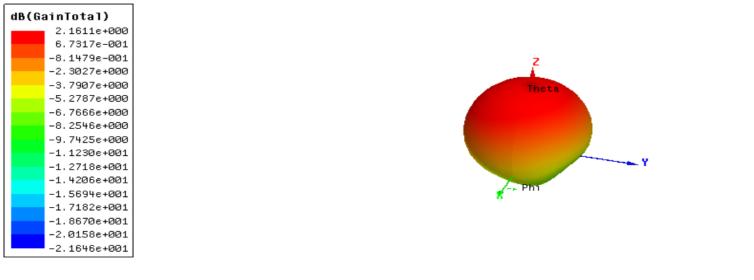
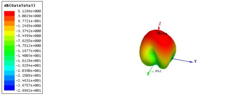
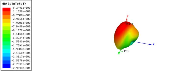
4.1 Gain
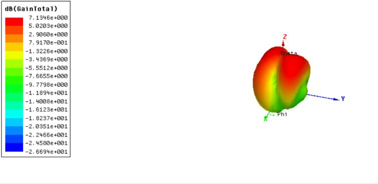
As per Antenna specification, gain parameter is one of themostcommonmeasurementstorealisetheabilityof theantennafortheeffectivetransmissionandreception. Gain value with 1*1 rectangular patch without slots using Fr4 substrate is 2.16 dB. Gain value with 1*1 rectangular patch with slots is 4.14dB and for the modified rectangular patch is 5.1dB.Also considering its array i.e 1*3 without slots shows a gain of 3.24dB also 1*3 with slots shows gain of 5.13dB and the modified onehasthegainof7.13dB.
4.2
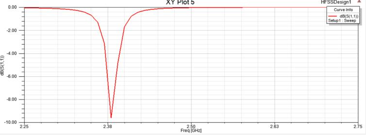
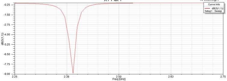
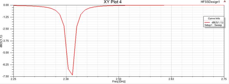
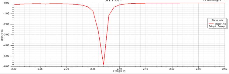
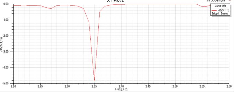
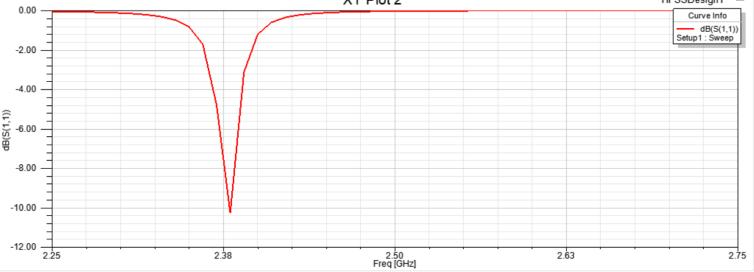
S11 representshow much power is reflected from the antenna,andhenceisknownasthereflectioncoefficient . Return loss value with 1*1 rectangular patch without slots using Fr4 substrate is -4.8 dB.Return loss value with 1*1 rectangular patch with slots is -5.8dB and for the modified rectangular patch is -7.3 dB.Also considering its array i.e 1*3 without slots shows return loss of -8.8dB also 1*3 with slots shows return loss of9.6dB and the modified one has the return loss of10.3dB.
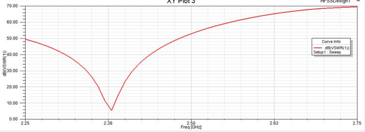
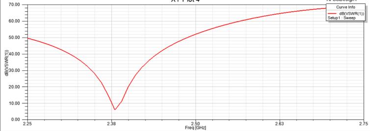
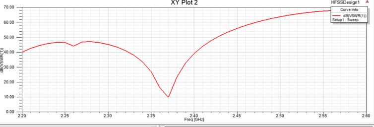
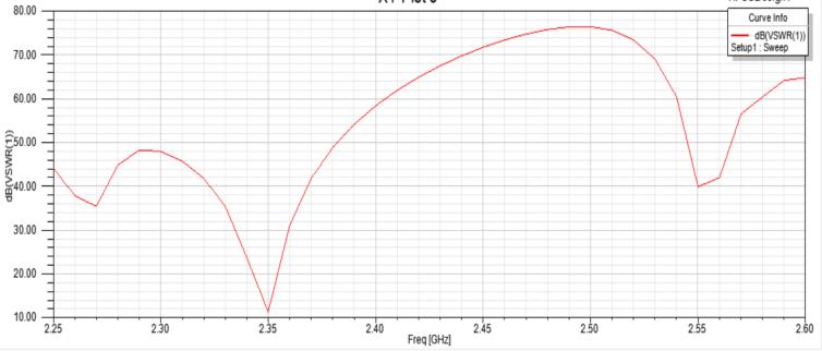
Voltage standing wave ratio (VSWR) is defined asthe ratiobetweentransmittedandreflectedvoltagestanding waves in a radio frequency (RF) electrical transmission system. It is a measure of how efficiently RF power is transmitted from the power source, through a transmission line, and into the load. VSWR value with 1*1 rectangular patch without slots using Fr4 substrate is 10dB.VSWR value with 1*1 rectangular patch with slots is 10 dB and for the modified rectangular patch is 5dB.Also considering its array i.e 1*3 without slots shows VSWR of 5dB also 1*3 with slots shows VSWR of 5dBandthemodifiedonehasVSWRof5dB.
5.Result
This study has proposed a design for a 2.4 GHz rectangular microstrip patch antenna for the WLAN applications. At first, rectangular patch antenna is designed without slots. After that, rectangular patch antennawasdesignedwithslots Laterrectangularpatch antenna was modified in such a way that there was improvement in antenna parameters .Also using same patch design array was formed with 3 elements. It was found that antenna array has better performance in termsofGain,returnlossandVSWRparameters.
6. Comparative Study
Table-3:PerformanceParameters
1*1RectangularPatch
1*3RectangularPatch
In this paper, various parameters of antenna such as Gain, Return Loss (S11) and VSWR were analyzed. Comparing single element with its array, a better Gain and S11 parameter was obtained performing the simulation on HFSS at 2.4 GHz resonant frequency. For high-speedprotocols,theS11parameteristhemostvital part. Also, since this research’s primary focus is the WLAN systems, the necessity of high-speed data transmissionisalsorequired.
9. Conclusion
Thenecessityofhighgainandadequateprotectionfrom pathloss will benecessary consideringthe expansion of modern technology in WLAN Systems . Considering the demand and numerous advantageous applications of WLAN systems, in this paper, using the HFSS 15 software, a rectangular shaped microstrip patch model antenna has been proposed to operate at a resonant frequency 2.4GHz. Moreover, it has also been deduced numerous parameters of the proposed antenna model, considering all the requirements and effectiveness. The designed model has a S11 value of -10.3 dB, a gain magnitude of 7.1 dB. However, considering the future demand, these parameters can be upgraded as per the requirements for overcoming the WLAN Systems challengesandenhancingtheantenna’sperformance.
REFERENCES
[1] Priya Upadhyay, Vivek Sharma, Richa Sharma, ``Design of Microstrip Patch Antenna Array for WLAN Application’’,IJEIT,Volume2,Issue1,July2012.
[2]Naresh Kumar Poonia, Krishan Kumar Sherdia, ``Microstrip Antenna Array for WiMAX & WLAN Applications’’,IJARCCE,Vol.2,Issue9,September2013.
[3]Anusury, K., Dollapalli, S., Survi, H., Kothari, A. and Peshwe,P.,2019,July.``MicrostripPatchAntennaFor2.4 GHz Using Slotted Ground Plane’’. In 2019 10th InternationalConferenceonComputing,Communication andNetworkingTechnologies(ICCCNT)(pp.1-6).IEEE.
[4]Ali, Y.E.M. and Jasim, K.A.S., 2015. ``Design of BroadbandMicrostripPatchAntennafor WLAN/WiMAX Applications’’. AL Rafdain Engineering Journal, 23(1), pp.154-163.
[5]Shantwng He and Jidong Xie, “Analysis and Novel Design of a Novel Dual Band Array Antenna with a Low Profile for 2400/5800 MHz WLAN Systems”, IEEE Transactions on Antennas and Propagation, Vol. 58, No. 2,pp.391-396,2010.
[6]Casu, G., Moraru, C. and Kovacs, A., 2014, May. ``Design and implementation of microstrip patch antenna array’’. In 2014 10th International Conference on Communications (COMM) (pp.1-4).IEEE
[7]Ramya, B., C. Supratha, and S. Robinson. "Design and Analysis of microstrip patch array antenna for WLAN applications." ICTACT Journal on Microelectronics 3.4 (2018):457-461.
[8]Asokan,V.,S.Thilagam,andK.VinothKumar."Design andanalysisofmicrostrippatchantennafor2.4GHzISM band and WLAN application." 2015 2nd International Conference on Electronics and Communication Systems (ICECS) IEEE,2015.
[9]Bala,B.D.,etal."Microstrippatchantennaarraywith gainenhancementforwlan applications." Bayero Journal Of Engineering And Technology (Bjet) 12.2(2017):18-25.
[10]Ayush Arora, Arpit Rana, Abhimanyu Yadav and R.L.Yadava.``Design of microstrip patch antenna at 2.4 GHz for Wi-Fi and Bluetooth applications”.``Journal of Physics(2021)”.