A STUDY AND DESIGN ANALYSIS FOR INJECTION MOULD FOR PLASTIC BEARING
D Karibasavaraja1, Anoop BM2, Harshith Raju3, Nandankumar J K4, Nirup A52,3,4,5 Under Graduate, Dept. of I&P Engineering, JSSTU, SJCE, Mysore, Karnataka, India

Abstract - Any products to be manufactured invariably require tools. Tool design and development is a specialized and critical area. Since tool is an aid for mass production, it should be accurate and economical for successful life of a product. Tool making is combination of art and science. Moulds are used to produce three-dimensional components. The economy and life of mould reacts entirely on the designer and his role is very important. The main objective is to have the detailed knowledge of the mould making techniques, tool processing in a properly planned and progressive manner. This presents an idea of fundamental necessary for processing the tool and to give a clear picture of manufacturing process.
Keywords: Injection, Toughness, Tensile, Ejection and Hardened
1.INTRODUCTION
This papergivesa detailedknowledgeofmouldmaking anddesigninginstep-by-stepandalsodifficultiesinvolved and skill of toolmaker. It is helpful for toolmaker by providing basic knowledge about design, raw material selection, manufacturing process etc. The information presentinthis papercanbe assetnotonlytoa toolmaker but also to any one concerned with tool making and production. Theaimofthis paperisto explain thetooling aspect involved starting from basic designing to finish stage of the injection mould in similar and clear manner. Anyproductstobemanufacturedinvariablyrequiretools. Tool design and development is a specialized and critical area.Sincetoolisanaidfor massproduction,itshouldbe accurate and economical for successful life of a product. Toolmakingiscombinationofartandscience.Mouldsare used to produce three-dimensional components. The economyandlifeofmould reactsentirelyonthedesigner and his role is very important. The main objective of the paperwork istohavethedetailed Practical-knowledge of the mould making techniques, tool processing in a properly planned and progressive manner. This presents an idea of fundamental necessary for processing the tool and to give a clear picture of manufacturing process, i.e., sequence of machining operations involved during manufacturingandassemblyofmoulds.Themainpurpose of choosing this component is, this component was different fromothercomponentwhichwasmanufactured earlier in that company and I have got more exposures to
learn different operations which was involved in it so I havechoosethistooltodomypaper
2. LITERATURE SURVEY
Nowadays almost an infinite variety of materials are available often specialized for a particular application. In most cases, the selection is unique and manufacturer’s assistance need to be taken. Bearing materials can be metallic or non-metallic. Metallic bearings are made of whitemetal,bronzes,aluminumbased,porousmetals,and coated metals. Non-metallic bearings are made of polymers, ceramics, and composites. Bearings can also be classified based on their geometry, half-round sleeves called as bearings and full round sleeves are called as bushes.
Property Babbitt metal Albased Cubased Polymer based
* All the numbers shown are arbitrary scale 1-High, 2Moderate,3-Low.
Teflon, nylon, phenolic, are used in the manufacture of polymer bearings. These are less in cost compared to metal bearings. Solid lubricants can be blended in their manufacture to improve their lubrication properties. Recent advances in manufacturing engineering polymers and understanding their properties has increased their use in the recent past. Polymer based composites were developed which combine high wear resistance, low
friction and wear rates and good thermal conductivity. There is flexibility, like blending solid lubricants, mixing various polymers in the melt phase, can be combined in layers, interwoven, impregnate into porous materials, to exactly suit the application. When compared to metals, Polymersarelessrigid.So,theyhaveconformability,good vibration absorption, good embeddability, high corrosion resistance, low wear rate. However, they have a high coefficient of thermal expansion about 5-10 times more thanmetals,havelowmeltingpointsthatlimittheiruseto light load applications. They adhere to materials like aluminum, so their use is also limited by shaft material. Polyamideimide coatings are widely used on aluminumbased linings with the addition of graphite or MoS2 as solid lubricants. These coatings are alternatives to the above electro-deposited and sputtered layers. These coatings poorly conduct heat. So, heat transfer from the bearing is less compared to metal coatings that limit the useofthesebearings.
3. PRESENT WORK
3.1 COMPONENTANALYSIS
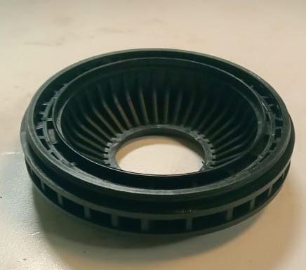
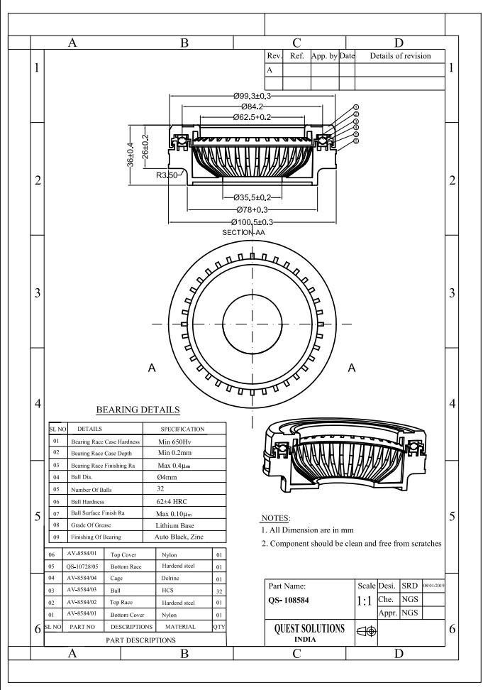
Thesuccessful designofa componentandtherelevant tooltoproducesuchcomponentlargelydependsonhow oneanalysisit.Thatis bothontechnical andcommercial aspects. A brief analysis of the component “BEARING” is givenbelow. Thecomponentanalysisdependsupon:
1. ComponentDetails
2. Functionofcomponent
3. Propertiesofcomponentmaterials
4. Criticaldimensionsofcomponent
3.2 COMPONENTDETAILS:
1. Name:Bearing
2. Material:NYLON66
3. Shrinkage:0.4-0.7%
4. Meltingtemperature:55-650C
5. Componentweight:120gms
6. Mouldtemperature:80-900C
7. Finish:Glossyfinish
8. Weightofmouldcomponentwithrunner:123gms
3.3 BRIEFSPECIFICATIONOFMOULD:
1. Typeofmould:Injectionmould.
2. Typeofinjectionmould:Twoplatemould
3. Numberofcavities:Singlecavity
4. Materialofthecomponent:Nylon66
5. TypeofRunner:Half-RoundRunner
6. Typeofgate:Spokegate
7. ShutHeight:350mm
8. Machineused:SHINEWELLServo120E
9. ClampingForce:95tones
Theproductdrawingisthebasisforconstructionmould. Designing requires a lot of planning and visualization of what can be accomplished by the resources at hand in a given time. A design with proper implementation and goodworkmanshipcanproduceaccurateparts.
This design is to construct a mould of 300X250mm size andashutheightof215mm,becauseofthe availabilityof
machine size and the maximum and the minimum, adjustmentofthemachineplaten.
The important factors to be considered while designing theinjectionmouldare:
1. Partingline
2. Feedsystem
3. Coolingofmould
4. Ejectionofcomponent
3.5 FACTORSTOCONSIDERWHILEDESIGNING:
1. Costing
2. Gatelocation
3. Machinerequirement
4. Easytomanufacture 5. Materialconsideration 6. Draft
7. Mouldshrinkage
8. Wallthickness
9. Specialfeatures
The selection of raw material plays a vital role in the manufacturingofthemould,whichhasa directimpacton the life of a mould. Different applications require specific characteristics for the material to be used. To select the material that provides the most economical overall performance and imparts necessary quality required is very important. The selection of material for a particular applicationisgovernedbytheworkingconditiontowhich it will be subjected. The raw material for tool can be chosen from the following-steel, cast steel, aluminum and copper.
Generally,mouldmakersusethefollowing4kindsofsteel withdifferentcomposition:
1. Lowcarbonsteel(<0.2%carbon)
2. Lowcarbonsteel(<0.2%carbon)
3. Mediumcarbonsteel(0.2to0.6%carbon)
4. Highcarbonsteel(0.7to1.3%carbon)
5. Alloysteel
The raw materials used in this mould are mainly tool steels. The raw materials distinguished by their special physical and mechanical properties influenced by the addition by alloying elements like Nickel, Vanadium, Chromium,Molybdenumsilicateetc.
3.7 PURPOSEOFADDINGALLOYINGELEMENTS:
1. Greaterwearresistanceforcutting/abrasion
2. Greatertoughnessorstrength.
3. Higherhardness.
4. Increaseshardenability.
5. Hothardness.
According to IS method a steel may be designated by a group of symbols indicating the important characteristics inthefollowingorder:
1. Tensilestrength
2. Carboncontent
3. Alloycontent
4. Sulphurandphosphorouslimits
5. Weldability
6. Surfacecondition
7. Surfacefinish
8. Steelquality
9. Treatment
3.8.EFFECTSOFALLOYINGELEMENTSONSTEEL
1. CARBON - This is very much essential for heat treatment. The carbon content of die steel generally doesnotexceed0.3to0.35%.
2. MANGANESE - Addition of more than 0.5% of manganeseincreaseshardensabilityandstrengthof steel. It is an excellent deoxidize. It increases the coolingrate.
3. SILICON - The increase in silicon content will raise the critical temperature, increases susceptibility to de-carbonization and graphitization and when combinedwithotheranalloypromotesresistanceto high temperature oxidation. Gives strength and toughnesstosteel.
4. NICKEL - Nickel permits lowering of carbon content to achieve a given strength level thereby increasing toughnessandfatigueresistance.
5. CHROMIUM - It improves hardness, wear resistance, toughness, corrosion resistance and it helps in retaininghigh surface finish.Itvaries from0.25%to 14%dependinguponthepropertiesrequired.
6. MOLYBDENUM - It restores hardness at elevated temperatures. It improves hardness; polish ability, toughness and mach inability. It eliminates temp brittleness in steels. It acts as a grain growth inhibitor
7. When steel is heated to high temperatures, molybdenum also intensifies the effects of other alloys.
8. TUNGSTEN - Increases hardness, strength and toughness up to 1.5% tungsten in steel increases wear resistance, retains hardness unto 600ºC to 650ºC.
9. VANADIUM - It is quite expensive, where as it increases the strength, hardness and impact resistance. It inhibits the grain growth during heating, permitting high temperature. The percentageofvanadiuminsteelvariesfrom0.15-2%.
Therearedifferent typesof mouldmaterialslikeHotdie steel, Cold work die steel, Cast steels, Aluminum, Copper etc.
Inthismouldthedifferentmaterialsusedare:
MildSteel
Oilhardenednonshrinkablesteel
PreHardensteel
MILDSTEEL:
1. Tradename:MS(MildSteel)
2. ISCodification:St-42
3. TensileStrength:42kgs/mm²
4. Carbon:0.22%
5. Silicon:0.65%
6. Phosphorus:0.05%
Thishashightoughnessandshockresistivepropertyso it is used in plates, locating ring, male hose ends etc. this material withstands the clamping force, injection and ejectionpressureandeconomical.
OILHARDENEDNON-SHRINKABLESTEEL:
1. Tradename:OHNS
2. ISCodification:T110W2CR1
3. Carbon:1.1%
4. Manganese:0.65%
5. Chromium:0.05%
This is a cold working tool steel whose important properties are good mach inability, high wear resistant and temperature resistant properties combined with remarkabletoughness.ThisisusedforSpruebush,ejector pins,Guiderills,etc.
PREHARDEN-STEEL:
1. Tradename:P20
2. ISCodification:T55Ni2Cr65Mo30
3. Carbon:0.24%
4. Manganese:0.5%
5. Chromium:13.3%
6. Nickel:1.40%
7. Molybdenum:0.35%
8. Vanadium:0.35%
9. Silicon:0.3%
3.9 MOULDTERMINOLOGYOFDIFFERENTPARTS
Injection mould is an assembly of parts containing withinitanimpressioninto whichtheplasticmaterial is injected and cooled. It is the impression, which gives the moulding it’s required from. The impression may be defined as the part imparts into the shape with accurate dimensionstothemoulding.
3.9.1.Topplate:
The Top plate is made of mild steel. This plate should be thickenoughtopreventbending;itwillbebiggerinwidth than the cavity plate. This plate is used for clamping the fixedhalftothemachineplaten.Itincorporatesa holefor spruebush,locatingring,guidepillaranda screwholefor arrestingthecavityplateandwedgehousings.
Material:St-42
QTY:1no.
3.9.2.Cavityplate:
This plate is used for fixing the cavity in position. In this plate component profile, are usually sparked on it. In this platespruebushholeisincorporated
Material:St-42
QTY:1no.
3.9.3.Coreplate:
This is a plate where core profile is machined so that it is inalignmentwiththecavity.Italsoprovidesprovisionfor incorporating guide bush, core back plate channel for arresting wear plates, guide rails and also a provision for pushbackpinsandejectorpins.
Material:St-42
QTY:1no.
3.9.4 Sidecore:
Side core is a local core that is normally mounted at right angletothedieaxisforformingprofilesinthesidefaceof a component. It gives the internal and external profiles to thecomponent;ithascriticalprofiles,whicharesparked.
Material:OHNS(T110W2Cr1)
QTY:04Nos
Hardness:54-56HRC
3.9.5.Pushbackpins:
These pins are fitted in the ejector plate and ends in the mould parting line. This is used only to retain the ejector assemblybackintoitspositionbeforethemouldcloses.
Material:OHNS(T110W2Cr1)
QTY:04Nos
Hardness:54-56HRC
3.9.6.Locatingring:
This is a disk-shaped part seated into a recess in the top plateonthecavityhalfofthetool.Itlocatesthemould on thefixedplaten.Beingaccurateitensuresalignmentofthe spruebushwiththecenterlineoftheinjectionunitnozzle.
Material:St-42
QTY:01No
3.9.7.Spruebush:
It is a headed cylindrical component about a tapered polished bore. The bush is positioned in the cavity half of the mould and provides an entry point for the machine injectionunittofeedthemould.
Material:OHNS(T110W2Cr1)
QTY:01No
Hardness:54-56HRC
3.9.8.FingerCam:
Thisarethe2pillar’swhichwillbefittedinanangleinthe cavity half and the front portion will be of 15⁰ taper and slight radius is made for the easy penetration and for the actuationsidecores
Material: P-20 (pre hardened steel) (T55Ni2Cr65 MoV30)
QTY:04Nos
Hardness:44-46HRC
3.9.9.Guiderails:
Theyareprovidedforguidingthesidecoreperpendicular tocoreaxiswithoutdistortion,stepisgroundintheserails toarrestcollarinthesidecore.
Material:OHNS(T110W2Cr1)
QTY:08Nos
Hardness:54-56HRC
3.9.10.Ejectorpins:
These are cylindrical moving pins used for ejecting the component.Itishousedintheejectorplate.
Material:OHNS(T110W2Cr1)
QTY:18Nos.
Hardness:56-58HRC
3.9.11.Ejectorplate:
This plate houses all the ejectors pins and push back pins withinit.
Material:St-42
QTY:01No.
3.9.12.Ejectorbackpalate:
Itisbacksupportiveplatefortheejectorassembly.
Material:OHNS(T110W2Cr1)
QTY:01No.
3.9.13.GuidepillarandGuidebushes:
Theseareusedinthetooltogetaccuratecomponentsand align moving half with fixed half when it is loaded on the machine.Thesearemadeupofoilhardenedsteel.
Material:OHNS(T110W2Cr1)
QTY:4Nos
Hardness 62-64HRC
3.9.14.Spacers:
Theseblocksareusedinthemouldtofacilitatetheejector assemblytobepositionedandactuated.
Material:St-42
QTY:02Nos.
3.9.15.BottomPlate:
This plate is incorporated next to the spacer. It provides enough room for the moving half to be clamped to the machine platen. It will be of more thickness to prevent buckling.
Material:St-42
QTY:01Nos
3.9.16.Screws:
Screwsareusedtoholdthepartstogetherofmouldings.
Material:STD
3.9.17.Subcoreinsert:
Theseinsertsarepressfittedintheholesprovidedinthe main core insert as per the design and the insert are screwedinthecounterboresprovidedatthebacksideof themaincoreinsert.
Material:P-20(prehardenedsteel)(T55Ni2Cr65 MoV3
Hardness:44-46HRC
QTY:01Nos
3.9.18.Wedge
Thispart isused tohold the sidecore rigidlyagainstthe injectionpressurewhenthemoldingisatworking
Material:MS(St42)
QTY:04Nos.
3.9.19.WedgeWearplate
This part is used to wear resistance of rubbing part of wedge and side core to with stand that rubbing the wear plateisused
Material:P-20(prehardenedsteel)(T55Ni2Cr65 MoV30)
QTY:04Nos.
Hardness:44-46HRC
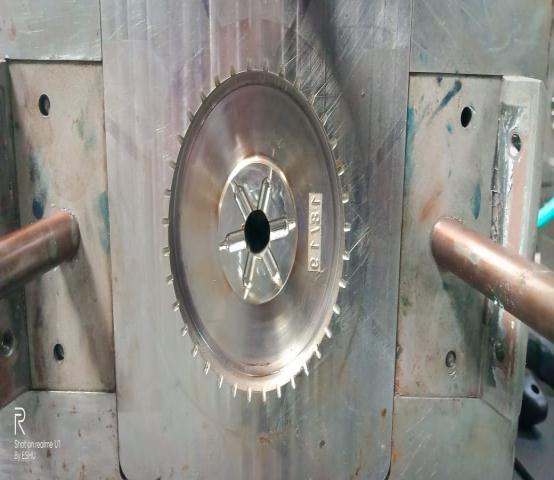
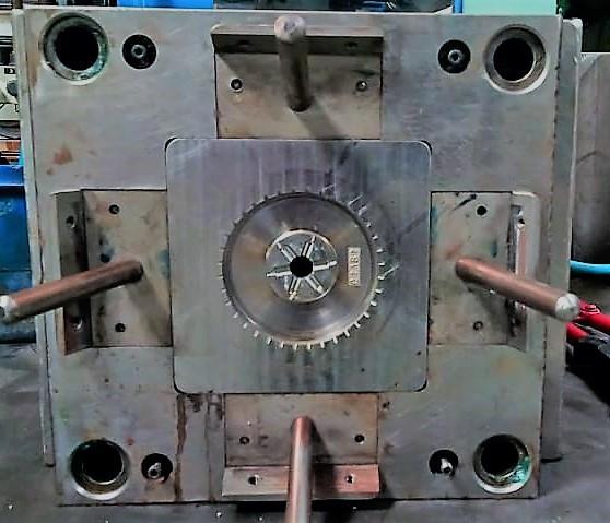
3.10.MANUFACTURINGPROCESS:
3.10.1.PartName:Cavityplate:(1no)
Material:MildSteel(St-42)
Cavity block was pre tooled and sized with allowance for furtheroperation.
1. Cavity plate was surface ground for reference; the holes are drilled as per drawing then moved for profilemachiningandspottingofscrewholesetc.
2. Boring of guide bush holes and reaming sprue bush holesweredoneinonesettingasperdrawing.
3. Inthenextsettingcollarforspruebushwasmachined andholesspottedasperdrawing.
4. The spotted holes were drilled and tapped as per drawing.
5. Cavity plate is moved to CNC for milling the housing forcavityinsertandwedges
6. The cooling cooling hole are matched with respect to maincavityinsert
7. Thecavitywasassembledalongwiththefingercams, sprue bush, cavity insert, wedge, finger cam and top plate.
8. Sprue bush was matched to the cavity face by grinding.
3.10.2.PartName:Coreplate:(1no)
Material:MildSteel(St-42)
1. Core block was pre tooled and sized with allowance forfurtheroperation.
2. Coreplatewassurfacegroundforreference;theholes are drilled as per drawing, then moved for profile machiningandspottingofscrew,ejectorholesetc.
3. Drilling, boring of guide pillar holes and reaming of pushback pinholes were done in same setting as per drawing.
4. The plate is moved to CNC for milling the housing of coreinsert
5. After completing the operation on CNC, the cooling holearematchedwithrespectthecavityinserts.
6. Finger cam relief slots were opened in the core plate asperthedrawing.
7. The spotted holes were drilled and reamed as per drawing.
8. The guide rails and wear plates were assembled to thecoreplateholesweretransferredtothecoreplate
3.10.3.PartName:GuideRails(8Nos)
Material:EN31
1. Four P-20 blocks were pre tooled by keeping 0.6mm stock with a grinding allowance per side. Right angle grindingwasdoneonallsides.
2. Spotting and drilling of screw holes, and reamed as perdrawing.
3. Thepartswereheat-treatedandinspected.
4. The blocks were ground according to the drawing to makeslidingforsidecoreassemblyaccurately.
5. Relief was provided at the side of the guide rails for preventingrubbingofsidecores.
3.10.4.PartName:Sidecore(04No)
Material:P-20(prehardenedsteel)(T55Ni2Cr65MoV1)
1. The Side Cores are pre tooled and are sized with allowanceforfurtheroperation.
2. Surface grinding of thickness and right angle is done onallsides.
3. Step milling with allowance for grinding as per drawing.
4. Thesidecoreswerethenmovedforprofilemachining.
5. The side core steps are ground accurately to the dimension and are made to slide easily through the guideways.
6. Side cores were angle drilled and angle milled as per thedrawing.
7. Side cores were then blue matched to the mating profiles
3.10.5.PartName:Ejectorplate
Material: Mildsteel(ST-42)
1. The Ejector plate is pre tooled and is sized with allowanceforfurtheroperation.
2. Surfacegrindingofthicknessandoneside rightangle for reference is done and the required size is maintained.
3. Drillingoftappedholesasperdrawing.
4. Ejector pin and push back pin collars were machined andreliefholeswerespottedanddrilled.
3.10.6.PartName:Retainerplate(Ejectorbackplate)
Material: Mildsteel(ST-42)
1. The Ejector back plate is pre tooled and is sized with allowanceforfurtheroperation.
2. Surfacegrindingofthicknessandoneside rightangle for reference is done and the required size is maintained.
3. Transferring of free hole and counter bore hole from tappedholefromejectorplateasperdrawing.
4. Drilling and machining of collar and relief holes in ejector back plate as per drawing for the purpose of assemblingapositiveretractionbush.
3.10.7.PartName:Spacers(2no)
Material: Mildsteel(ST-42)
1. The Spacers are pre tooled and are sized with allowanceforfurtheroperation.
2. Surfacegrindingofthicknessandtwosidesrightangle isdone.
3. Transferring of free holes from tapped holes from corebackplate.
4. Drilling of tapped holes in spacers for the purpose of screwing.
3.10.8.PartName:Bottomplate
Material: Mildsteel(ST-42)
1. The Bottom plate is pre tooled and is sized with allowance for further operation. Surface grinding of thickness and one side right angle for reference is doneandtherequiredsizeismaintained.
2. Drilling of relief hole for retraction bush as per drawing.
3. Transferringfreeholeandcounterboreholefromfree holeofspacers.
3.10.9.PartName:Spruebush
Material:OHNS(T110W2Cr1)
Hardness:54-56HRC
Turningofthebushisdonewithallowanceforgrinding,
1. Through hole having a less diameter than the minimumdiameterofthetaperholewasdrilled.
2. Bush was sent for heat treatment, after which cylindrical grinding of fitting area was done to have pushfitincavityblock.
3. Then the collar and total height was maintained by surfacegrinding.
4. Then sprue bush is sent for WEDM where the sprue holewaswirecutandthecutportionwaspolished.
5. After every operation stage inspection was done and finallyinspectedpriortoassembly.
3.10.10.PartName:Subcoreinsert
Material:P-20(prehardenedsteel)(T55Ni2Cr65MoV1)
Hardness:44-46HRC
Turning of the insert is done with kept allowance for furtheroperation
Volume: 10 Issue: 02 | Feb 2023 www.irjet.net p-ISSN: 2395-0072
1. After turning we send it for CNC because we can’t manufacture the rib portion of component in conventionalmachining
2. The insert has to move to CG to get accurate OD because it is fitted in the main insert and the plastic materialhasdonotenterintothemaininsert.
3. TheBarffel coolingholehastobedrilled totheinsert asperdrawing
4. DrillingcoredrillforM8threads
After completing all operation, it will inspect for prior assembly
4. CONCLUSION
Bearing single cavity mould was completed successfully andthecomponentsproducedinthetrialswereexcellent, which satisfied the requirement of the customer. The intensionofthis paperistogivea clearpictureofgeneral procedureofmouldmanufacturingandmachiningprocess involved in mould making. Working on this mould has been greatly beneficial in more practical knowledge and has acquired the spirit of team work and discipline. This paperwillbeareferenceformyfutureendeavors.
REFERENCES
1. R.G.W.PYE-InjectionMouldDesign
2. WICKVEILLEUX-QualityControlandAssembly
3. HOWARDEBOYER-HeatTreatment
4. R.S.NAGESH-TheoryofMoulds
5. GLANVILL AND DENTON - Injection Mould Design Fundamentals
6. JABRYDSON-PlasticMaterials
7. GLAESERW-MaterialsforTribology
8. HARNOY A - Bearing Design in Machinery: EngineeringTribologyandLubrication:CRCPress.
9. HAMROCKBJ, SCHMIDSR, AND JACOBSONBOFundamentals Of Fluid Film Lubrication: Taylor & Francis.
10. STURK.R AND WHITNEY.W - Fluid Film Bearing Materials.
BIOGRAPHIES
Karibasavaraja D, Assistant Professor, Department of I&P Engineering,JSSTU,SJCE,Mysore

Anoop BM, Undergraduate, Department of I&P Engineering, JSSTU,SJCE,Mysore


Harshith Raju, Undergraduate, Department of I&P Engineering, JSSTU,SJCE,Mysore
Nandankumar JK, Undergraduate, Department of I&P Engineering, JSSTU,SJCE,Mysore
NirupA,Undergraduate,Department of I&P Engineering, JSSTU, SJCE, Mysore