International Research Journal of Engineering and Technology (IRJET) e-ISSN:2395-0056

Volume: 10 Issue: 01 | Jan 2023 www.irjet.net p-ISSN:2395-0072
International Research Journal of Engineering and Technology (IRJET) e-ISSN:2395-0056
Volume: 10 Issue: 01 | Jan 2023 www.irjet.net p-ISSN:2395-0072
1 K. Pavitra 2 DrJ.sreenivasulu 3Dr.M. Anka Rao 4Smt.Y.Manasa
1PG-Scholar, Department of EEE 2,3Assistant professor, 4Assistant professor (adhoc), Department of EEE JNTUA COLLEGE OF ENGINEERING, ANANTAPUR, A.P ***
Abstract:
As a result of the recent surge of interest in renewable energy, scientists have made great strides in developing effective technologies for converting renewable energy. This includes traditional power grids, alternative energy sources, and battery packs. This research proposes partial power conversion (PPC) between two DC buses as a novel AC/DC hybrid multi-port power routing(MPPR) system
Power from one source, such as a photovoltaic array, is converted into another, such as a series-connected DC bus, only when needed. This is known as Partial Power Conversion. Two DC voltage buses and a PV port are included in this setup. Grid-connected inverters have a high-voltage ride-through (HVRT) feature that allows them to function normally even during a grid voltage surge. PV ports can utilise maximum power point tracking (MPPT) technology. Because just a small amount of power from the PV panel is allowed to flow to the seriesconnected DC bus, and because constant DC voltage is maintained with Fuzzy logic control (FLC), the PPC-based PV conversion feature achieves lower loss than full power conversion (FPC) for PV. MATLAB/Simulink simulations are used to produce the results.
Index:HVRT,MPPT,PPC,FPC,MPPR
Asaresult,theusageoffossilfuelsandcarbonemissions havedecreased,whilerenewableenergysourceslikethe Photovoltaic system have swiftly advanced. There has been a lot of research into how to make PV conversion more effective and cheaper. While the low flow cost, compact structure, and high efficiency of a single-stage PV power-generating system are all advantages, gridconnected inversion cannot be accomplished under typicalPVpowerconditions.Two-stagePVconversionis widely employed because of the pliability it provides in terms of Maximum power point, energy, and control. Partial power conversion, which can be employed in non-isolated conversion applications, is highly efficient and cost-effective because it only evaluates a considerable proportion of the system's total energy. Inspired by the work in [1], a new method of partial
power conversion was proposed. A standard push-pull forwardconvertertypicallyachievespowerflowcontrol and voltage adjustment in a three-phase power distribution system. In reference, a high-efficiency DC/DCconverterwasproposedtobeusedindistributed PV systems of varying sizes. High efficiency is achieving partialpowerprocessingandcoordinatingtheoperation of the interleaved channels of the converter. The ability to remove energy or smooth PV output with quick response The problem of voltage over limit and fluctuation caused by PV grid-connected can be effectively alleviated through the rational configuration of BES [3], [4]. Now, the tradition-centralised power generation is gradually changing to the coexistence of centralised and distributed power generation. The unidirectional flow mode of power is gradually transforming into multidirectional modes. To improve the energy utilisation of the PV-battery grid-connected system, the electrical power router has communication and intelligent choice capabilities, which are supported by the mature application experience of microgrid and information technology integration-making capabilities and can realise active management of power network energy flow based on network operation state and user and control centre instructions, while also improving system power utilisation effectively [5]. [6] proposed a quad-port power routing circuit that integrated storage and distributed generation, such as Photovoltaic, and enabled the implementation of power quality features. The authors of reference [7] suggested a multi-port power routing (MPPR) converter that integrates PV and batterypowerforhighstep-upapplications,aswell asa controlstrategythatmadeuseofenergystoragetokeep the Maximum power point of PV constant across a wide range of illumination and load conditions, to realise the multi-mode and efficient operation of the PV power generation system. Research on low-voltage ridethrough solutions for PV systems has progressed tremendously as HVRT is still developing. Scholars have conductedearlyresearchintoHVRTtechnologyforgridconnected devices. An HVRT control method with adaptive DC bus voltage adjustment in response to grid voltagevariationswaspresentedtoremedythesituation where power was being sucked back into the grid from the grid-side converter. Protecting the grid against
International Research Journal of Engineering and Technology (IRJET) e-ISSN:2395-0056
Volume: 10 Issue: 01 | Jan 2023 www.irjet.net p-ISSN:2395-0072
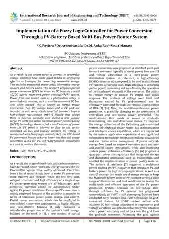
instability when using significant amounts of wind powerrequiresasolutionbasedonthecombinationofa series impedance divider and parallel high impedance grounding at the wind turbine terminal. To accomplish the MPPT of PV and HVRT of the grid-connected converter by volume compression, an extra port is createdfortheMPPRsysteminFigure1basedonPPC.A power routercomprises a PVport,a battery port,anAC port,andtwoDCvoltagebuses.Theauxiliaryportaidsin implementingthePVMPPTwithaPCthatonlytransmits power determined by the electric potential difference between the DC bus and the PV panel. The Photovoltaic panels connected to the DC bus must be handled within the loop, which significantly reduces the loss compared totheFPCforPV.Inthescenariowherethephotovoltaic conversion is unaltered, the HVRT of grid-connected converters is likewise achieved through voltage modulation.
employed to supply power to their respective loads and transfer energy between them. The DC bus of a threephase converter is constructed by connecting a PV port and a PPC port in sequence to create Bus 1. The BES's poweristransmittedvia Bus2,andthestabilityofu3is regulated using buck/boost converters. To realise the transfer control of BES and partial PV power, a nonisolated dual half-bridge (DHB) links Bus 1 and Bus 2. Battery energy storage, or BES, is a technology used to storepowergeneratedbyrenewableresourceslikesolar and wind. To adapt the voltage from the BES to the system’s needs, buck/boost converters are used. Power converters known as Dual Half-Bridges (DHBs) are commonly employed to transfer energy across two DC buses.PartialPowerConversion,alsoknownasPPC,isa method for transforming the energy created by the disparitybetweentheDCbusandthePVmodule.
Fig1TheMPPRtopologyofPV-batterygrid-connected system.
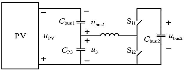
Asshowninfig1.AtotalofthreeportsandtwoDCbuses make up the system. A power router comprises a PV port, a battery port, an AC port, and two DC voltage buses. The primary power source of the system is accessible through Port 1. Accessing the BES via Port 2 allows for modulation and augmentation of the PV output.TomanagethepowerproducedbytheMPPTand HVRT implemented by the voltage differential between the DC bus and the PV module, port 3 is a PPC port. HVRTstandsforHighVoltageRideThrough,atechnique used to ensure that the PV system can continue to operate even when the grid voltage is higher than the rated voltage Bus 2 is controlled by a bidirectional dual half-bridge (DHB) DC/DC converter, whereas bus 1 is controlled by a three-phase converter connected to the grid. The coordination of Bus 1 and Port 3 is also essentialfortheMPPTdeploymentofPVarrays.TheBES controls the charging and discharging processes to improve the system’s overall energy efficiency. Two separatedirectcurrents(DC)buses,Bus1andBus2,are
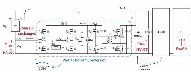
Fig2:TheequivalentmodelofPPCandHVRT.
From fig 2: For a PV array's maximum power point tracking to be effective, the voltage at Port 3 (u3) must be dynamically adjusted to maintain a constant maximumpowerpointatthearray'soutput.Thiskindof partial power conversion uses a non-isolated converter to actualise the PPC, which boosts energy transfer efficiency. When only a fraction of the power is converted, this process is called partial power conversion (PPC). Compared to Full power conversion (FPC), which transfers 100% of the power, this method only assigns a portion of the energy. Realising the PPC with non-isolated converters can increase energy transfer efficiency while decreasing the system's size, weight, and price. The proposed PPC scheme in this papercanalsoassistincarryingouttheHVRTunderthe grid voltage surge condition. After all the loads are connected to the DC bus via a power electronic converter, the voltage on Bus 1 uBus 1 may fluctuate within a certain range. As AC side voltage spikes are detected,theDC bus voltageuBus1can beincreasedvia Port3tocompensate.The MPPTcontrol determinesthe PV output voltage uPV, and the DC bus voltage uBus1 is foundbyaddingthevoltageatPort3(u3)tothevoltage at the PVs (uPV). As the DC side of the three-phase converter experiences a voltage spike from the grid, the voltageatPort3(u3)shouldbeincreasedtokeepthePV system working at the MPPT. If there is a high-voltage failure, the voltage on Bus 1 will need to be raised to
International Research Journal of Engineering and Technology (IRJET) e-ISSN:2395-0056
Volume: 10 Issue: 01 | Jan 2023 www.irjet.net p-ISSN:2395-0072
accommodate the higher demand for power at Port 3, whichu3=uBus -uPV.
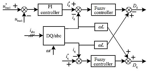
The control scheme of Bus1 voltage uBus1 is shown in Figure3.Voltageandcurrentdoubleclosed-loopcontrol areusedinthegrid-connectedcondition.Sincereference values id,iq and feedback values id,iq are DC signals in steady state, current tracking control without steadystateerrorcanberealisedthroughtheFUZZYcontroller According to the control scheme of the converter, the control objective is that the voltage and power can be matchedinreal-timetomaintainthestabilityofboththe Dc link voltage and perform the MPPT. The voltage at Bus 1 is regulated as shown in Figure 3. This control approach is utilised in the grid-connected mode, which uses voltage and current double closed-loop control. A Fuzzy controller is utilised to achieve current tracking withzerosteady-stateerror,andboththereferenceand feedbackvalues(id,iq)areDCsignalsatrest.
IftheequationQGrid +QPV −QLoad1 >0holds,energyfrom the three-phase converter is sent to Bus 2 via the DHB bi-directional DC/DCconverter whentheconverterisin rectifier mode. This equation mathematically represents the direction of energy flow, with QGrid representing the grid'sreactivepower,QPVrepresentingthePV'sreactive power,andQLoad1representingtheloadconnectedtoBus 1.IftheequationQGrid +QPV −QLoad1 <0,thentheenergy is transferred to Bus 1 through the DHB bi-direction DC/DC converter. When the three-phase converter is in inverter mode, the energy is transferred to Bus 2 through the DHB bi-direction DC/DC converter if the equation QPV − QGrid − QLoad1 > 0. Where QPV is the reactive power of the PV, QGrid is the reactive power of the grid, and QLoad1 is the reactive power of the load linkedtoBus1,thisequationrepresentsthedirectionof energy flowmathematically. Ifthe equationQPV −QGrid − QLoad1<0
Maintaining a constant DC bus voltage and completing Maximum Power Point Tracking (MPPT) of the Photovoltaics (PV) in a grid-connected state are two goals of the converter's control approach that require real-time matching of voltage and power. The control strategyofthesystemisbasedontheconceptofvoltage modulation. This means that the voltage of the auxiliary port is modulated to control the PV maximum power point tracking (MPPT) and high-voltage ride-through (HVRT) of the grid-tied inverter. Depending on the system'senergyrequirements,theconvertercanworkin inverterorrectifiermode.
Two DC voltage buses, one for connecting batteries and oneforconnectingsolarpanels,makeupFig.4.Howthe solar photovoltaic (PV) array, the bus load, and the battery energy storage (BES) interacts determines the system'senergyflowdirection.
TheDHBbidirectionalDC/DCconvertersendsthepower to Bus 1. When the BES discharges, the energy is transferred to Bus 1 through the DHB converter if the following equation is true: QBES − Qu3 − QLoad2 > 0. Here, QBES is the power output of the BES, Qu3 is the power output of the PV port, and QLoad2 is the power outputoftheloadconnectedtoBus2.Ontheotherhand, if the equation QBES − Qu3 − QLoad2 < 0 is true, then the energy is transferred to Bus 2 through the DHB converter.TheenergyistransferredtoBus2throughthe DHBconverterwhentheBEScharges.
Inpart,fuzzyLogicControllers'successcanbeattributed totheir intuitive similarity toa humancontroller.Like a human operator, it uses a knowledge base and the associated if-then rules to perform its functions. Compared to alternative methods of control, this one requireslesseffortandstudyofcomplexmathematics.
International Research Journal of Engineering and Technology (IRJET) e-ISSN:2395-0056
Volume: 10 Issue: 01 | Jan 2023 www.irjet.net p-ISSN:2395-0072
always being sent via the buck/boost circuit to the capacitor CP3 to increase the voltage at the Ports 3 terminals. After doing the math, we find that a value of 2000 W, or roughly 1/6 of PV capacity, is the partial power conversion value. During 0-1s, the grid's current andvoltageareinphaseandatthesamefrequency.The three-phase converter has entered rectifier mode to transferenergyfromthepowergridtoBus1.Waveforms of the voltage and current at a steady state in the inductance used for phase shifting, L3, are shown along withtheoutputcurvesfrom the controllerinthephaseshiftingcontrolmodule.
The FLC is simple to operate and develop because it requires only a qualitative understanding of the system. Linguistic variables, specified by membership functions, are then used to process the inputs to a Fuzzy Logic Controller. It is intentional that the membership functionsselectedencompasstheentirelinguisticspace. Adjacentfuzzysetsmustoverlaptopreventabehaviour gap in response to subtle input shifts. Fuzzy Logic Controllers have a concise time constant. Hence this requirementiscrucialtotheirdevelopment.
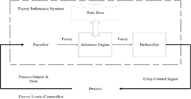
Fig6:simulationdiagramofthecontrolsystem
The simulation will involve changing the working conditions to verify the system's functioning principle undervarioussettings.
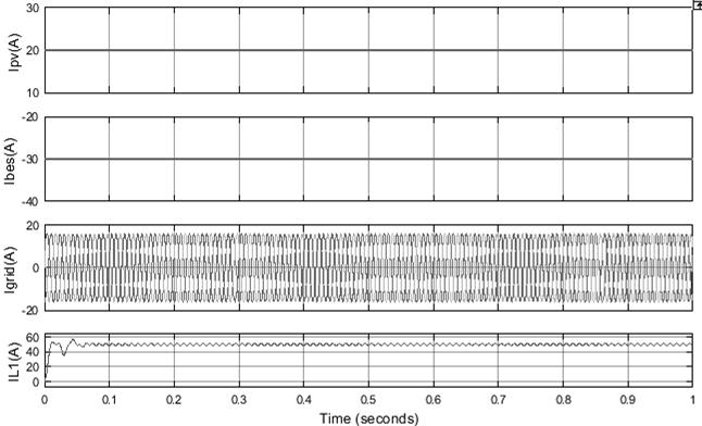
CaseI:Figure7depicts thepre- andpost-switchvoltage uBus1 conditionsforBus 1. Bus 2operatesata voltageof 400V. The current u3 at Port 3 is 100V. Constant 30A current is used to power the BES. Indefinitely maintaininga47Acurrentatitsoutput,thePVmoduleis reliable. The inductive current iL1 shows that energy is
Fig7SimulationresultofcaseI


International Research Journal of Engineering and Technology (IRJET) e-ISSN:2395-0056
Volume: 10 Issue: 01 | Jan 2023 www.irjet.net p-ISSN:2395-0072
Fig8:Steadystatewaveformin0-1s
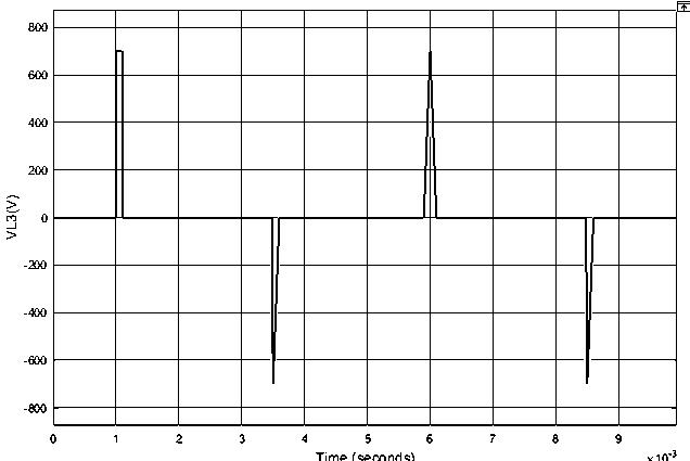
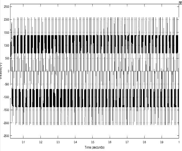
Fig9:Invertervoltage
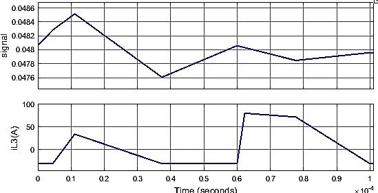
Theoutputcurvesof the controllerof the phase-shifting control module and the steady-state waveforms of the voltage and current of the phase-shifting inductance L3 are shown in Figure 10. The controller’s output is positive,andtheDHBbi-directionDC/DCconverterisin the forward operating mode. The energy is transferred toBus2through theDHBbi-directionDC/DCconverter. During1-2s,thethree-phaseconverterworksininverter mode. Power is transferred to the grid side through Bus 1. The output of the controller of the phase shift control module is negative, and the DHB bi-direction DC/DC converter is in reverse operating mode. The energy is transferred to Bus 1 through the DHB bi-direction DC/DCconverter.Thecurrentandvoltagewaveformsof inductancebothreachasteadystate.
International Research Journal of Engineering and Technology (IRJET) e-ISSN:2395-0056
Volume: 10 Issue: 01 | Jan 2023 www.irjet.net p-ISSN:2395-0072
The simulation time is 2.5s; the system works in HVRT conditions for 1-2s. The simulation results are shown in Figure 12. The current direction in the system structure diagramisthepositivedirection.
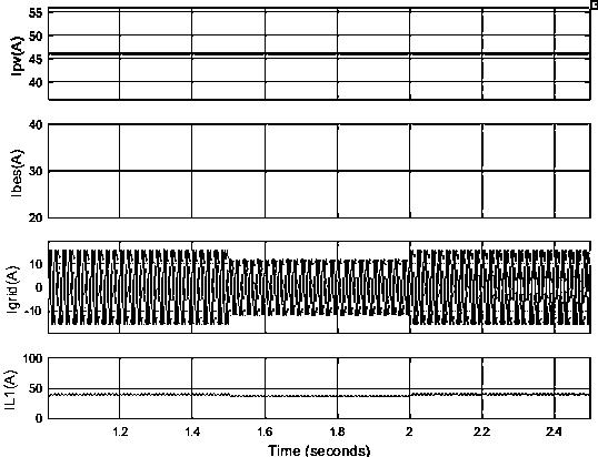
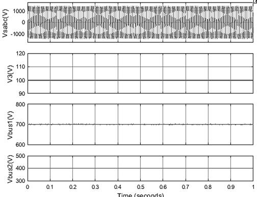
Case II: As shown in Figure 12, during 0-1s, the BES is charged with a constant current of 30A, and all loads in the system are switched into 10• ; during 1-1.5s and 22.5s, the BES discharges at a continuous current of 30A, and the DC bus is not connected to the load. The output current of the PV is increased to 30A. During 1.5 2s, basedontheoperationinthelastworkingcondition,the grid voltage rises. Under the normal operation state of grid voltage, DC bus voltage uBus1 is 700V; DC bus uBus2is400V.ThePort3voltageu3is100V.During1.52s, the grid voltage rises, and the DC bus voltage uBus1 is stable at 860V, while the Port 3 voltage u3 is stable at 260Vasshowninfig13.
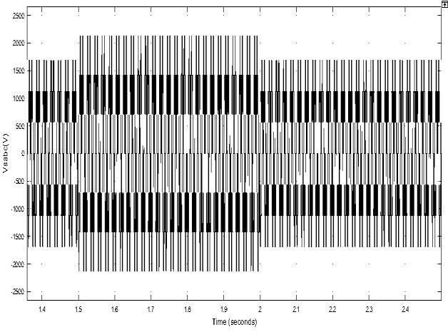
Fig14:InverterVoltage
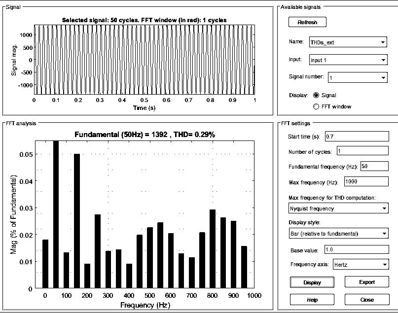
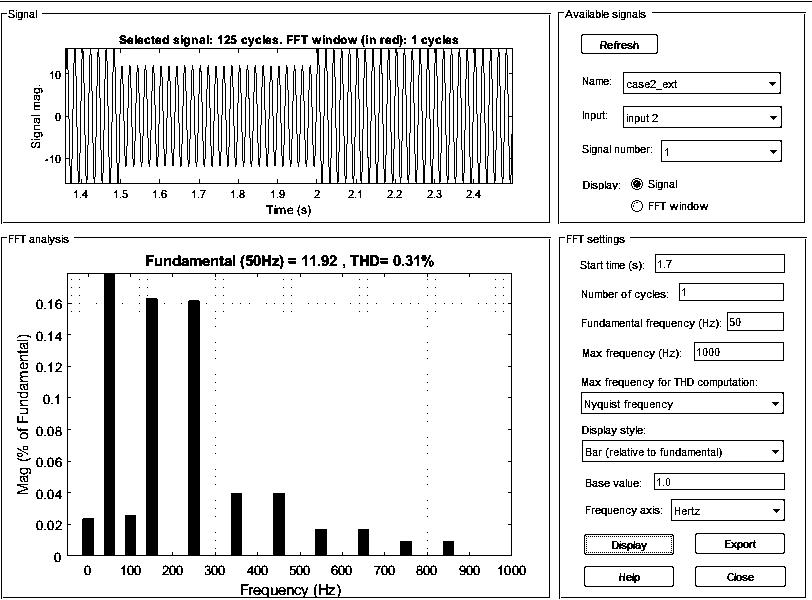
Fig15:VoltageTHD
Fig12:currentsofPV,BES,andinductor
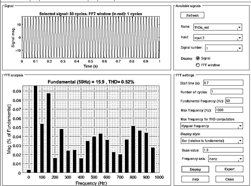
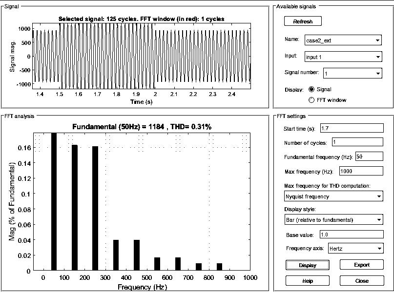
Fig16:CurrentTHD
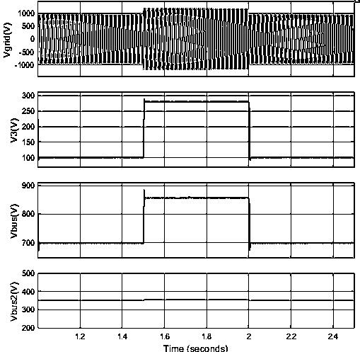
Fig13:Gridvoltage
International Research Journal of Engineering and Technology (IRJET) e-ISSN:2395-0056
Volume: 10 Issue: 01 | Jan 2023 www.irjet.net p-ISSN:2395-0072
Under normal operating conditions, the buck/boost converter transfers some energy from the inductor current iL1 to the capacitor CP3 to raise the voltage at Port3. Thecost perkilowatt-hourofPPCisroughly1/6 ofthatofPVpower.Still,HVRTonlymakesuseofaround half of the PV capacity. The voltage and current on the gridareinphaseandatthesamefrequencyduringthe01 s. Bus 1 receives power from the power grid via the three-phase converter operating in rectifier mode. The DHB bi-directional DC/DC converter is in forward working mode to transfer energy from Bus 2 to Bus 2 when the energy supplied by the BES is insufficient to match the load power consumption and partial power conversionontheBus2side Voltageandcurrentareout of frequency and phase during 1-1.5s and 2-2.5s. The three-phase converter is now operating in inverter mode. To the side of the grid, energy is sent via Bus 1. The energy storage device's charging requirements and the energy utilised for partial power transformation are both met by the PVsystem because the powerof the PV panelshasbeenraised,andthereisnoloadconnectedto thebus.Also,thesurpluspowercanbefedbackintothe grid. DHB's bidirectional DC/DC converter, working in forwardmode,transferscontroltoBus2.
Comparison Table of conventional method (PI) and the proposedmethod(FUZZY):
VOLTAGETHD CURRENTTHD
PIRegulator 2.48% 2.45%
FUZZY 0.29% 0.52%
Conclusion:
Thispaper will review a methodof using solar batteries as part of a multi-port power routing(MPPR) scheme. One key aspect of the MPPR proposed in this study that sets it apart from the standard PV-battery gridconnected system is that it achieves partial power conversionoftheDC/DCstagethroughasingleauxiliary port. Under the presumption of constant PV output, MPPR uses HVRT as a backup system. Altering the DC bus voltage of the three-phase converter to raise the grid-side voltage is taken care of by the auxiliary port. The system's three ports, two DC buses, and the grid allow various power exchange combinations; by incorporating fuzzy logic, both the PV current and the THDmightbeenhanced.
References:
[1] Hassan, S. Z. Mumtaz, S., Kamal, T. and Khan, L., "Performance of grid-integrated photovoltaic/fuel cell/electrolyser /battery hybrid power system, “power
generation System and Renewable Energy Technologies (PGSRET).
[2] YANPING ZHU, YAKUN WANG, JIAXUN TENG , XIAO FENG SUN , (Member, IEEE), MENG QI, WEI ZHAO, AND XINLI,“PartialPowerConversionandHighVoltageRideThroughSchemeforaPV-BatteryBasedMultiportMultiBusPowerRouter”IEEETRANSVOLUME9,2021
[3] M. Mao, C. Qian, and Y. Ding, ``Decentralized coordination power control for islanding microgrid based on PV/BES-VSG,'' CPSS Trans. Power Electron. Appl.,vol.3,no.1,pp.1424,Mar.2018.
[4]H.MyneniandS.K.Ganjikunta,``Energymanagement and control of single-stage grid-connected solar PV and BES system,'' IEEE Trans. Sustain. Energy, vol. 11, no. 3, pp.1739-1749,Jul.2020.
[5]H. Zhao, L. Yao, and W. Wang, ``Large scale wind power high voltage off grid analysis and coordinated prevention and control strategy,'' Power Syst. Autom., vol.39,no.23,pp.4348and65,2015.
[6] S. Falcones, R. Ayyanar, and X. Mao, ``A DC to DC multiport converter based solid-state transformer integrating distributed generation and stor age,'' IEEE Trans.PowerElectron.,vol.28,no.5,pp.2192-2203,May 2013.
[7]M.S.Agamy,M.Harfman-Todorovic,A.Elasser,S.Chi, R.L.Steigerwald,J.A.Sabate,A.J.McCann,L.Zhang,and F. J. Mueller, ``An efficient partial power processing DC/DCconverterfordistributedPVarchitectures,''IEEE Trans. Power Electron., vol. 29, no. 2, pp. 674-686, Feb. 2014.
[8] Y. Liu, S. You, and Y. Liu, ``Study of wind and PV frequency control in U.S. power gridsEI and TI case studies,'' IEEE Power Energy Technol. Syst. J., vol. 4, no. 3,pp.65-73,Sep.2017.
[9] H. Sugihara, K. Yokoyama, O. Saeki, K. Tsuji, and T. Funaki, ``Economic and efficient voltage management using customer-owned energy storage systems in a distribution network with high penetration of photovoltaic systems,'' IEEE Trans. Power Syst., vol. 28, no.1,pp.102-111,Feb.2013.
[10] Y. Cai,W. Tang, O. Xu, and L. Zhang, ``Review of voltagecontrolresearchinLVdistributionnetworkwith high proportion of residential PVs,'' (in Chinese), Power Syst.Technol.,vol.42,no.1,pp.220-229,2018.
[11]J.Xu,N.Liu,L.Yu,J.Y.Lei,andJ.H.Zhang,``Optimal allocation of energy storage system of PV microgrid for industries considering impor tant load,'' (in Chinese),
Power Syst. Protection Control, vol. 44, no. 9, pp. 29 to 37,2016.
[12] X. Fu, Q. Fu, and W. Tang, ``Grid connection techniquebasedontheoryforatwo-stagePVstructure,'' IET Power Electron., vol. 12, no. 6,pp. 15451553, May 2019.
[13] R. Chinnappan, P. Logamani, and R. Ramasubbu, ``Fixed frequency integral sliding-mode currentcontrolled MPPT boost converter for two stage PV generation system,'' IET Circuits, Devices Syst., vol. 13, no.6,pp.793to805,Sep.2019.
[14]Y.Du,D.D.-C.Lu,G.M.L.Chu,andW.Xiao,``Closedformsolutionoftime-varyingmodelanditsapplications for output current harmonics in two-stage PV inverter,'' IEEETrans.Sustain.Energy,vol.6,no.1,pp.142to150, Jan.2015.
International Research Journal of Engineering and Technology (IRJET) e-ISSN:2395-0056 Volume: 10 Issue: 01 | Jan 2023 www.irjet.net p-ISSN:2395-0072 © 2022, IRJET | Impact Factor value: 7.529 | ISO 9001:2008 Certified Journal | Page423