International Research Journal of Engineering and Technology (IRJET) e-ISSN: 2395-0056

Volume: 10 Issue: 01 | Jan 2023 www.irjet.net p-ISSN: 2395-0072
International Research Journal of Engineering and Technology (IRJET) e-ISSN: 2395-0056
Volume: 10 Issue: 01 | Jan 2023 www.irjet.net p-ISSN: 2395-0072
1PG Student [EPS], Dept. of EE, KCES’S College Engineering. And Management, Jalgaon, Maharashtra, India, 2 Assistant Professor, Dept. of EE, KCES’S College Engineering and Management, Jalgaon, Maharashtra, India ***
Abstract - Electrified cars are on track to become a critical component of the transportation business over the next several years. As a result, the charging infrastructure should be designed concurrently. The many approaches and strategiesforelectric carcharging systems are presented in this study. Fast charging stations with solar PV integration,predictive controllers based charging stations, PV-assisted EV fast charging stations, MPPT Algorithms for Solar PV based Charging Stations, and Multiport Converter based EV Charging Stations are all discussed in this article. This report will be beneficial to future researchers and students who are interested in working on solar pv based quick charging stations for electric car design.
Keywords – Electric Vehicle, Charging Station, Fast Charging, MPPT.
Since the last decade, electric cars (EVs) have become increasinglypopular.Theprgressivedepletionoffossilfuels suchascrudeoil,coal,naturalgas,andheavyoil,whichare soughtbytheexpandingpopulationsofindustrialisedand emerging nations, is driving up demand [1]. Electric cars have become a class that is further divided into Hybrid Electric Vehicles (HEVs)2 and Plug-in Hybrid Electric Vehicles(PHEVs)3duetocontinualeffortsandpioneering research initiatives in the Battery Management System (BMS)forapplicationsinEVs.AlthoughthemajorityofEVs currently on the market are both HEVs and PHEVs, the desireforPHEVsisclearlyhigher.Thisisowingtothefuel flexibility provided by these cars, which can run on both traditional fuels like petroleum and gas as well as electric powerstoredinabattery(energystoragedevice).
Theword"electricvehicle"isusedinthisdocumenttorefer to any mode of transportation that employs rechargeable batteries,suchascars,buses,motorbikes,andtrucks.The riseinelectricvehiclenumbershascreatedanewproblem: increased grid power consumption. Decentralizing power generation, such as incorporating renewable energy local sourcesintocharginginfrastructure,isoneeffectivewayto mitigatetheeffects.Liuetal.[2]reportontheconnection betweenrenewableenergyandEVchargingproblemsinthe presenceofsmartgridtechnologytoaddressthisproblem.
value:
TherecanbefourdifferentscenariosforchargingofEVs.
2.1 Uncontrolled Charging or the end-of-travel charging:
This is a common charging arrangement for an electric vehicleparkedathome.Itdoesnotrequireanysophisticated control technology to determine how and when charging takesplace.Furthermore,itprovidesnoinformationonuser behaviour or incentives, such as time of use rates (ToU). Based on a standard residential 110/120 volt 20 Ampere circuit with a continuous rating of 1.8-2.0 kW, a constant charging rate of 1.4 kilo Watt (kW) is assumed for this application. Even with this slow charging pace, a fully chargedbatterytakesaboutsixhourstocharge.
Thisissimilartoend-of-tripcharging,howeveritonlystarts chargingafter10p.m.Inthisinstance,atimer,eitherinthe carorinthecharger,isrequiredtomanagepoweruse.ToU may be used with just a small increase in infrastructure. Because of the current incentives for off-peak energy consumption, utility firms are more likely to choose this situation.ResidentialconsumerscangetToUpricesfroma variety of utility companies, including Xcel Energy. The charging rate is 1.4 kW, which is identical to the uncontrolledchargingscenariodescribedabove.
In this scenario, all charging takes place overnight in residential areas, with the goal of providing the most efficient,low-costchargingpossiblesincecarchargingmay beregulateddirectlyorindirectlybyalocalutilityprovider. The car would respond intelligently to a real-time pricing indication in the event of indirect control. For maximum system optimization, the charge rate is raised to 3.2kW duringoff-peakcharging.Thisishigherthanthecontinuous chargerateofatypicalresidentialcircuit,anditimpliesthat 240V/40Amperelevel2chargersareusedfor20%ofall charging.Thechargingperiodisestimatedtoberoughlysix hours.
International Research Journal of Engineering and Technology (IRJET) e-ISSN: 2395-0056
Volume: 10 Issue: 01 | Jan 2023 www.irjet.net p-ISSN: 2395-0072
2.4 Continuous Charging or Publicly available electricity charging:
This scenario is identical to the end-of-trip charging scenario,butitassumesthattheelectriccarischargingata publicchargingstation.Vehiclesarechargedanytimethey arestationaryformorethananhour,eventhoughcharging duringoff-peakhoursisrecommended.Thisisanexampleof uncontrollable charging as well. The utilisation of this chargingprofilepeakstwiceaday,usuallyinthemorning andevening.
TheSocietyofAutomotiveEngineering(SAE),theCHAdeMO association, and the International Electro-technical Commission are three major organisations that seek to standardiseelectricalcharacteristicsofEVchargingstations acrosstheworld(IEC).Asidefromtheseorganisations,Tesla Motors, the world's leading electric vehicle manufacturer, establishesitsownstandardsforitsModelS,ModelX,and Roadsterelectricvehicles.
Everyorganisationlistedaboveoffersavarietyofcharger standards that function with both AC and DC power. The SAE, for example, has been working on standard J1772, whichdivideselectricvehiclechargersintothreelevels[5]: Level1,Level2,andLevel3.
i) Level 1: The charger is built-in and delivers DC voltage withamaximumcurrentof80Aandapoweroutputof40 kW.
ii) Level 2: The charger gives a DC voltage of up to 200 A withamaximumoutputof90kW.
iii) Level 3: The charger is disconnected from the board. Withamaximumcapacityof240kW,thecharging station deliversDCelectricitystraighttothebatterythroughaDC connection.
Level3chargersareallconsideredfastchargers.CHAdeMO and the International Electrotechnical Commission (IEC) suggestedvariouspowerandcurrentrequirementsforDC rapidcharging.Aquicksummaryofpowerandcurrentlevel evaluation for electric car DC charging standards is presentedintable1foradditionalinformation.
Standard Level
SAE
CHAdeMO DCFastCharging 125 62.5
IEC DCFastCharging 400 100-200
Tesla DCSuperCharger 340 136
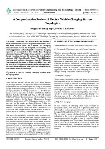
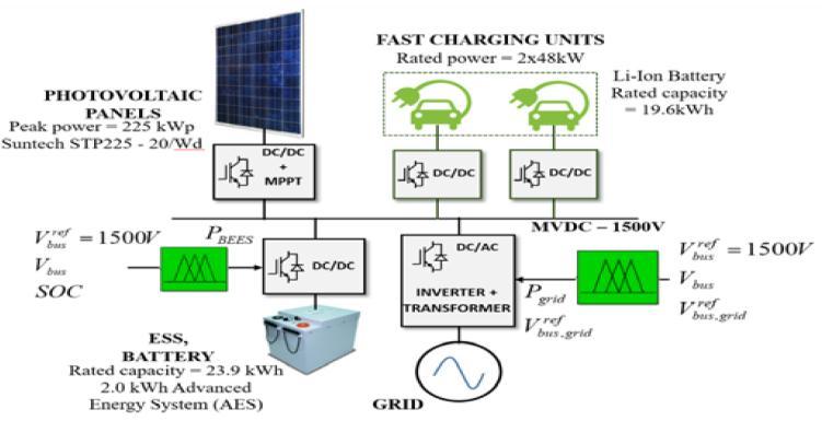
PabloGarca-Trivio[3]andhiscolleaguespresentedarapid chargingstationthatincludedasolar(PV)system,anenergy storagesystem(ESS),andalinktothelocalgrid.TheFCScan operate as a stand-alone system for the most part, with occasional grid support, thanks to this arrangement. The voltage management of the common medium voltage DC (MVDC) bus,towhichall theenergysourcesarelinked, is usedtoregulatethem.Asaresult,thePVsystem,theESS,or thegridareemployedtosupplytheenergyrequiredbythe EVs,dependingontheirvoltage.
Two48kWfastchargingunits(FCU)areusedintheEVFCS underinvestigation(Fig.1),whichmaybepoweredbyaPV system,aLi-ionbatterypack(ESS),orthegrid.Accordingto theIEC61851-1,thisFCSisclassifiedas"Mode4,DClevel2." For managing the power balance between them and the MVDCbusvoltage,alloftheFCU'scomponentsarelinkedto a1500VDCvoltage(MVDC) throughDC/DCconverters.A DC/ACconverterandatransformerareusedtoconnectto thegrid.
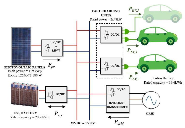
The creation of high-power electric vehicle (EV) fast chargingstations(EVFCSs)thataredirectlyconnectedtothe medium-voltage(MV)gridisapossiblemethodforreducing EV charging time. The charging station's cascaded-highfrequency-link(CHFL)technologyoffersanisolatedpower electronicinterfacebetweenthestation'slowvoltage(LV) DC bus and the three-phase MV AC power network. A
International Research Journal of Engineering and Technology (IRJET) e-ISSN: 2395-0056
Volume: 10 Issue: 01 | Jan 2023 www.irjet.net p-ISSN: 2395-0072
high/medium frequency transformer is used in the CHFL systemtoofferisolationandahighstepping-upratio.The enormousnumberofactiveswitchesisthesystem'sbiggest drawback.
converter connects the BSB to the DC bus, converting the battery'slowvoltagetothebusvoltage.Buckconvertersare solely used to charge EVs using a variety of charging modalitieslinkedinparalleltomodalitieslinkedinparallel toPV/BSB.EachchargingstationhasaHumanControlPanel (HCP)withinformationsuchasthebattery'sStateofCharge (SOC),timetoload,batterycapacity,andpowernecessaryto achievethespecifiedSOC.Anotherparameteristhevehicle's business name/model in order to correctly adapt the appropriatechargingmodeandestablishtheprioritylevelto loadwheninsufficientpowerisdetectedattheCS.
TheCHFLsystemisdepictedinblockdiagramforminFigure 2.Ahalf-bridgematrixconverterisusedinthecelltopology. ThereisnodcconnectionintheCHFLsystemwiththiscell architecture.Asaresult,itqualifiesasaCHFACLsystem.For ncells,thesecondarywindingsofthetransformerare2n.As seeninfig.2,eachcelliscoupledtotwosecondarywindings. Theprimarywindingandoneofthesecondarywindingsof thetransformerhaveaturnsratioof1:m.ThePVmodules are linked to a VDC LV DC bus (this voltage reference is derivedusingthemaximum powerpointtracking(MPPT) technique shown in [5]. When the duty cycle of a single phase inverter is 50%, the voltage at the transformer primarysideis–VDCfor50%oftheperiodictimeandVDC forthebalanceoftheperiodictime.Forhalfoftheperiodic time, the voltage at one of the transformer's secondary windings'terminalswillbe(-m.VDC),andfortheremainder of the periodic time, it will be (m.VDC). Because each cell operatesinabi-polarmanner,itcanoutputeither(m.VDC) or(–m.VDC).ThecellmayconverttheHFvoltagetoalow frequency voltage component by adjusting the timing of realisationofthesetwovoltagelevels.
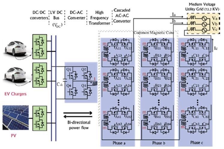
SeveralelementsthatimpacttheCSyieldarelinkedtothe coupling of a photovoltaic-grid system (PVGS) and an electricvehiclechargingstation(EVCS)[6].Externalinputs, like as weather data, geographical position, and the daily ratedpoweroftheCS[7],aredeemedcrucialtocomplete thedesign.Achargingstationarchitecturewaspresentedby A.HASSOUNEetal [12],asshowninFig.3.PVarray,EVs, andBSBareallconnectedtoaDCbus;thediagramdepicts bothDCandACbuses.
The PV system is linked to the DC bus through a DC/DC boostconverterthatusesanMPPTalgorithmtoextractthe maximum power from the PV system. The buck/boost
Pablo Garca-Trivio [11] and colleagues introduced a new decentralisedchargingstationcontrolapproachbasedona medium-voltagedirect-current(MVDC)bus.Thesecharging stationsarepartofamicrogridthatincludesaPVsystem,a battery energy storage system, a local grid link, and two rapid charge units. The referenced decentralised control approachbasedonfuzzylogic,whichincludesthestateof charge of the battery energy storage system as a control variable, is the primary contribution of their study. This controlcontainstwoindependentfuzzylogicsystems(one forthebatteryenergystoragesystemandtheotherforthe grid), initial state-of-charge of the battery energy storage system, and number of EVs connected to the charging station.
ADCMbasedonseparatefuzzylogiccontrollersisaimedto replace this type of control. This structure allows each componenttofunctionindependentlywithoutknowingthe stateoftherestofthesystem,removingthetheoreticaland practical limitations of power supply dependability and facilitatinglarge-scalegeneratoraccess[13].
International Research Journal of Engineering and Technology (IRJET) e-ISSN: 2395-0056
Volume: 10 Issue: 01 | Jan 2023 www.irjet.net p-ISSN: 2395-0072
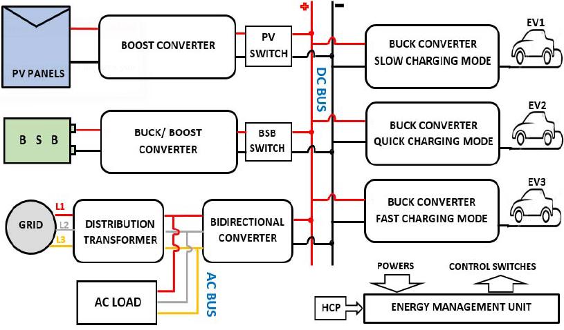
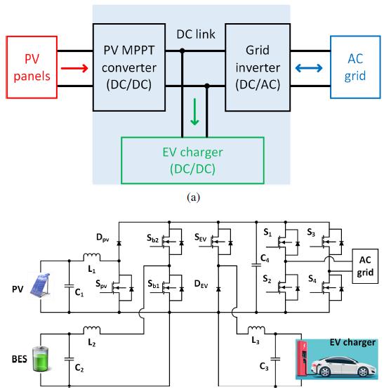
All three power sources, including PV and EV charger unidirectionalsources,andACgridbi-directionalsource,are connected through three independent converters in the traditionalarchitectureofDCbuschargingstationwithPV integrationfigure6.
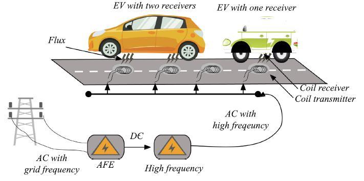
Typically,electricvehiclesystemsaremadeupofanumber ofmodulesthatworktogethertoprovidethevehicle'shigh power and track stability. The charging mechanism is connectedtothebulkofthesecomponents.Inthiscontext, dynamic wireless power transfer is a viable solution for addressing electric car range anxiety while also lowering onboardbatterycosts.Inaddition,thestatusofthevehicle, whether it is moving or not, determines various characteristicssuchasvehiclespeedandcoilreceiversizes anddiameters.
Onemorebi-directionalpowersourceBESsharesthesame DCbusintheproposedDCbuschargingstationfigure6.The BESisusedtokeeptheDClinkvoltagestableandbalancePV power surpluses and shortages figure 6. The purpose and operationmodesofthissetupmaybeexploredindepthas follows.
Inthismode,theswitchesSpv,Sb1,andSb2areturnedoff whileSEVisturnedon.Therefore,PVdirectlydeliverspower totheload.
Thesystemisdividedintotwocomponents,onefortheroad andtheotherforthecar.Thepermanentportionontheroad is known as the transmitter. The moving receiver is the secondcomponent,whichislocatedbeneaththevehicle.The twopartsareseparatedbyavacuum,andeachportionhas itsownelectronicsystem.Thetransmitterblockproducesa high-frequencyalternatingmagneticflux.
AsshowninFig.5,thetransmittersectionismountedonthe roadandconnectedtoaseriesofelectricalcomponentsthat provideflexibilitybetweenthereceiversandtheACpower supply.ItshowstheoriginalenergyACpowerlinkedtothe active front end (AFE) converter, which generates a programmableDCvoltage.Apowerfactorcorrector(PFC) block is added to this area of the transmitter block to maintain grid stability by monitoring the reactive power comingfromthesourcetothetransmitter.
BES is discharged to the EV load when Spv and SEV are turnedonwhileSb1andSb2areturnedoff.
BES is charged from the PV surplus energy when Sb2 is turnedonandSb1,Spv,andSEVareturnedoff.
PVtoBES,GridtoEV,andPVtoGridaretheothermodes.
Table II summarises the operational principles of various modeslikeasPVtoBES,gridtoEV,andPVtogrid. TableII: EVChargingOperatingModes
Spv Sb1 Sb2 SEV Power flow
OFF OFF OFF ON PVtoEV
OFF OFF ON OFF PVtoBES
ON OFF OFF ON BEStoEV
International Research Journal of Engineering and Technology (IRJET) e-ISSN: 2395-0056 Volume: 10 Issue: 01 | Jan 2023 www.irjet.net p-ISSN: 2395-0072
vehicles using renewable energy for sustainable transportation. IET Power Electron 2019;12:627–38. doi:https://doi.org/10.1049/iet-pel.2018.5127.
IwouldliketoshowgratitudetomyguideProf.P.D.Kulkarni forsharingtheirpearlsofwisdomwithasduringresearch.I am also grateful to KCES’ college of engineering and managementwhoprovidedlabs,instrumentsandexpertise thatgreatlyassistresearch.AtlastbutnotleastIamthankful tomyparentsforsupportingme.
This study examined multiple energy transfer types, charginglevels,andprocedures,aswellasthecurrentglobal standards for EV charging, to offer a better knowledge of EVCStechnology.Thereisacomparisonandexplanationof the many components of the charging stations. To summarise,thephotovoltaicchargingstructureisgrowing increasinglycomplicatedasadditionalfunctionsareadded intothesystem,necessitatingsophisticatedcontrolsineach blockaswellasreal-timestationmanagement.
[1] C.Gan,J.Wu,Y.Hu,S.Yang,W.CaoandJ.M.Guerrero, "New Integrated Multilevel Converter for Switched Reluctance Motor Drives in Plug-in Hybrid Electric Vehicles With Flexible Energy Conversion," in IEEE Transactions on Power Electronics, vol. 32, no. 5, pp. 3754-3766,May2017.
[2] L.Liu,F.Kong,X.Liu,Y.Peng,andQ.Wang,‘Areviewon electric vehiclesinteracting with renewable energyin smart grid’, Renew. Sustain. Energy Rev., vol. 51, pp. 648–661,2015.
[3] García-Triviño,Pablo,etal."Controlofelectricvehicles fast charging station supplied by PV/energy storage system/grid." 2016 IEEE International Energy Conference(ENERGYCON).IEEE,2016.
[4] Elsayad,Nour,andOsamaA.Mohammed."Acascaded high frequency AC link system for large-scale PV assisted EV fast charging stations." 2017 IEEE Transportation Electrification Conference and Expo (ITEC).IEEE,2017.
[5] Hassoune,A.,etal."SmarttopologyofEVsinaPV-grid system based charging station." 2017 International ConferenceonElectricalandInformationTechnologies (ICEIT).IEEE,2017.
[6] Joseph PK, Devaraj E, Gopal A. Overview of wireless charging and vehicle to grid integration of electric
[7] MillerJM,OnarOC,ChinthavaliM.Primary-sidepower flow control of wireless power transfer for electric vehiclecharging.IEEEJEmergSelTopPowerElectron 2015;3:147–62. doi: https://doi.org/10.1109/JESTPE.2014.2382569
[8] MoosaviSA,MortazaviSS,NamadmalanA,IqbalA, AlHitmi M. Design and Sensitivity Analysis of Dynamic Wireless Chargers for Efficient Energy Transfer. IEEE Access2021;9:16286–95.doi:https://doi.org/10.1109/ ACCESS.2020.3048029.
[9] T.Kamal,M.Nadarajah,S.Z.Hassan,H.Li,F.Mehmood, and I. Hussain, “Optimal Scheduling of PHEVs in a PV basedChargingStation,”pp.1–6