International Research Journal of Engineering and Technology (IRJET) e-ISSN: 2395-0056

Volume: 10 Issue: 01 | Jan 2023 www.irjet.net p-ISSN: 2395-0072
International Research Journal of Engineering and Technology (IRJET) e-ISSN: 2395-0056
Volume: 10 Issue: 01 | Jan 2023 www.irjet.net p-ISSN: 2395-0072
1,2,3,4Students, Department of Mechanical Engineering 5Professor, Department of Mechanical Engineering Pimpri Chinchwad College of Engineering and Research, Ravet, Pune, Maharashtra, India ***
Abstract - The primary goal of this research and development project is to Design and develop a pick and place robot for industrial use. The system is so designed that it eliminates human error and human intervention to get more precise work. This robotic arm can pick and place objects. The robot was designed, assembled, implemented in various fields such as; in bottle filling industry, and packing industry, and then programmed using a pneumatic circuit. The end effector is designed to grab the object, lift it and place it in the desired location.
Theuseofpickandplacerobotsiscommoninproduction lines with repetitive tasks. A human doing the same task over and over again will be inefficient and mentally disturbedbecauseitbecomesarepetitive,tedioustaskwith ease,andspeed:allowingforfastercycletimesandaccuracy incomparisontohumancounterparts.Theconsistentoutput along with its quality and repeatability are unmatched. Industrialrobotsaremachinesthatareusedintheindustry, and they are usually automatically controlled and reprogrammable.Theycanbeusedinthreeormoreaxes, whichmakesthemversatileandabletodoavarietyoftasks. The design of the robot was determined by the cylinder specificationsandweightrequirementsoftherobot.Inthe industrialmanufacturingsector,pickandplacerobotshave been used in a variety of material-handling applications rangingfrompalletizinganddepalletizing,casepicking,bin picking, kitting, machine loading and unloading, parts feeding,andpartsdelivery.Suchrobotswithimprovements havealsobeenusedinstorage/retrievalsystemsandcase packingandsorting.
Theprojectentailsthedesign,construction,andpneumatic circuitry of a 3-DOF robot. This design served as the inspiration for the robot's fundamental mechanics. Following pneumatic cylinder selection, the required link lengthsweredeterminedandmadeusingcarbonsteelbars. Thefinaldesignoftherobotisasfollows.Thedesignofthe robot underwent significant changes throughout the assembly.
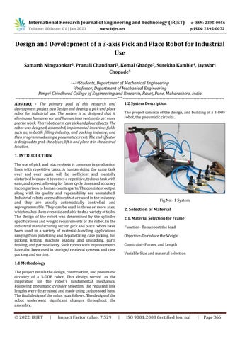
Theprojectconsistsofthedesign,andbuildingofa3-DOF robot,thepneumaticcircuits
FigNo:-1System
Function-Tosupporttheload Objective-ToreducetheWeight Constraint-Forces,andLength Variable-Sizeandmaterialselection
International Research Journal of Engineering and Technology (IRJET) e-ISSN: 2395-0056
Volume: 10 Issue: 01 | Jan 2023 www.irjet.net p-ISSN: 2395-0072
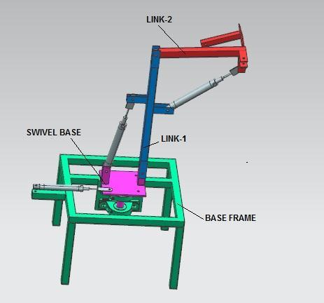

Fig -2: CADDesign
As Pneumatic air is the main source for working of the project.Themainairsourcewillbesuppliedtothepower pack of the project which includes 4 no. of 5/2 handoperatedvalves.
Thefirst5/2Valvegivenforrotationofallthelinksmeans alllinksassemblywillberotatedtowardsthestrokelength ofthefirstcylinder.
Thesecond5/2Valveisgivenfortakingmomentagainstthe centralpivotpointanditisplacedatsomedistancefromthe centralarmwhichisvertical.
Third 5/2 Valve given for taking moment against inclined notperfecthorizontalbutgivenlengthwisemomenttoup anddown.
Fourth5/2Valvegivenfortakingforkmoment.
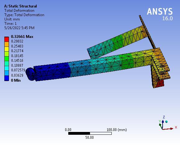
Fig -4: Link2
Theanalyticalstressis28.82MPatherebysuggestingthat thedesignoflink-2issafeunderagivensystemofforces. 3.1.1. Deformation
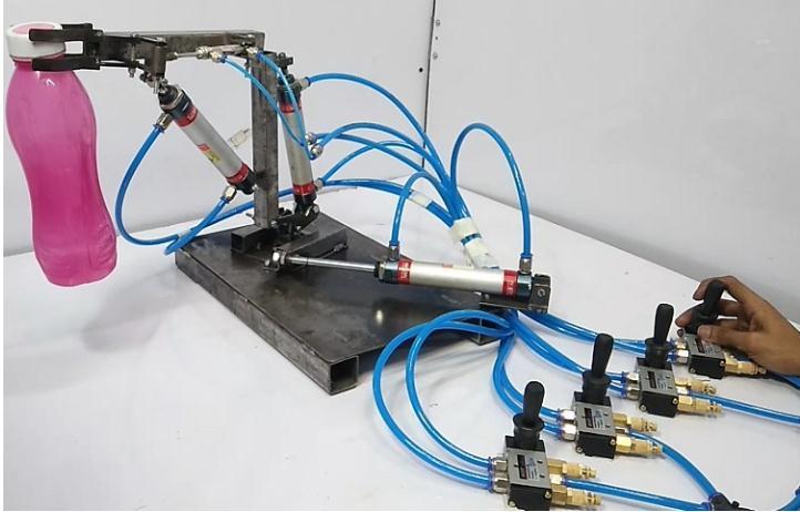
Fig -5: DeformationofLink2
The maximum deformation is 0.32661 mm which is very negligiblehencethelink-2issafeundera givensystemof forces.
Fig -3:DesignAnalysis
International Research Journal of Engineering and Technology (IRJET) e-ISSN: 2395-0056
Volume: 10 Issue: 01 | Jan 2023 www.irjet.net p-ISSN: 2395-0072
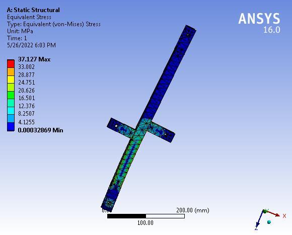
Fig -4: Link1
Theanalyticalstressis37.127MPatherebysuggestingthat thedesignoflink-1issafeunderagivensystemofforces.
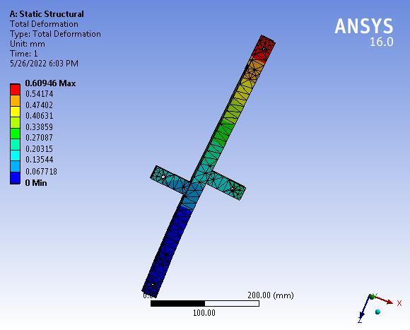
Fig -5: DeformationofLink1
The maximum deformation is 0.609 mm which is very negligiblehencethelink-1issafeundera givensystemof forces.
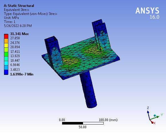
Fig -6: SwivelBase
Theanalyticalstressis31.341MPatherebysuggestingthat thedesignoftheSwivelbaseissafeunderagivensystemof forces.
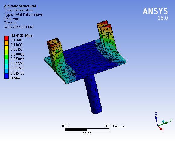
3.3.1. Deformation of Swivel Base
Fig -7:
The maximum deformation is 0.14185 mm which is very negligiblehencetheSwivelbaseissafeunderagivensystem offorces.
International Research Journal of Engineering and Technology (IRJET) e-ISSN: 2395-0056
Volume: 10 Issue: 01 | Jan 2023 www.irjet.net p-ISSN: 2395-0072
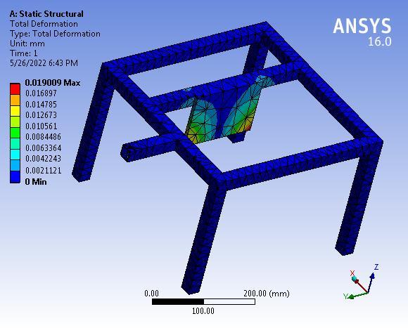
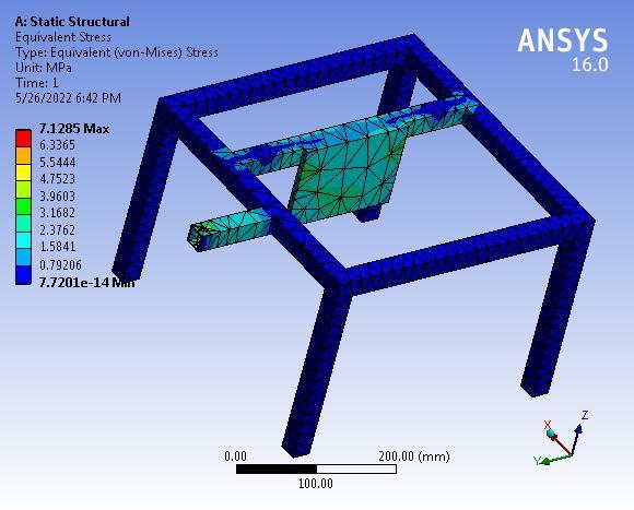
Von-mises Stresses: Fig -8: BaseFrame
Theanalyticalstressis7.1785MPatherebysuggestingthat thedesignoftheBaseFrameissafeunderagivensystemof forces.
The maximum deformation is 0.019 mm which is very negligiblehencethebaseframeissafeunderagivensystem offorces.
The system works well till 12 kg but fails at 13 kg. The analyticalstressis37.127MPatherebysuggestingthatthe designoflink-1issafeunderagivensystemofforces.The maximumdeformationis0.609mmwhichisverynegligible hencethelink-1issafeunderagivensystemofforces.The analytical stress is 28.82 MPa thereby suggesting that the designoflink-2issafeunderagivensystemofforces.The maximum deformation is 0.32661 mm which is very negligiblehencethelink-2issafeundera givensystemof forces. The analytical stress is 31.341 MPa thereby suggestingthatthedesignoftheSwivelbaseissafeundera given system of forces. The maximum deformation is 0.14185mmwhichisverynegligiblehencetheSwivelbase issafeunderthegivensystemofforces
We would like to take this opportunity to thank Prof. J.V.ChopadeandPimpriChinchwadcollegeof Engineering and Research, Ravet for the invaluable support, guidance, andfacilitiesprovided.
[1] NishigandhaPatel1,VaibhavAhuja1,ShaunakHedaoo1, Tushar Rotti1, A Review Paper on the Pick and Place RoboticArm,IRJETVolume08|02,February2021.
[2] AutomationofMobilePickandPlaceRoboticSystemfor Small Food Industry, IEEE 2012. Mir Sajjad Hussain TalpurandMurtazaHussainShaikh.
[3] DesignandImplementationofMulti-HandlingPickand PlaceRoboticArmbyS.Premkumar,K.SuryaVarman, andR.Balamurugan,IJETTMarch2016.
[4] Pick and Place Robotic ARM Using PLC, Abhiraj Bhalerao,PrasadDoifode,KunalChopade,andJitendra Gaikwad,IJERTAugust2019.
[5] S.Mohanavelan,M.MadhanKumar,K.Mohanprabhu,M. Narendhiran4,B.OmAdhavan,DesignandAnalysisof PickandPlaceRobot,IJESC2019.
[6] Dr.T. Sunil Kumar, K. Sarath, Sd.Famil, A.V.S.Bhagyesh andSk.Althaf,Design,andfabricationofpickandplace roboticarm,ResearchGateAugust2020