International Research Journal of Engineering and Technology (IRJET) e-ISSN:2395-0056

Volume: 10 Issue: 01 | Jan 2023 www.irjet.net p-ISSN:2395-0072
International Research Journal of Engineering and Technology (IRJET) e-ISSN:2395-0056
Volume: 10 Issue: 01 | Jan 2023 www.irjet.net p-ISSN:2395-0072
[1]Mukesh Kumar Dewangan, [2] Prof. Vivek Kushwaha, 1Gyan Ganga College of Technology, Jabalpur (M.P.)India, 2 Gyan Ganga College of Technology, Jabalpur (M.P.) India.
APowerqualityproblematicisanoccurrenceestablishedasamodifiedvoltage,currentorfrequencythatresultsina failure or a mis-operation of end handler equipments. Utility distribution networks, sensitive industrial loads and critical commercial maneuvers suffer from various types of outages and service disruptions which can cost important fiscal losses. With the reformation of power systems and with shifting trend towards distributed and discrete generation, the issue of powerqualityisgoingtotakecontainerdimensions.InemergentcountrieslikeIndia,wherethevariationofpowerfrequency andmany suchother causesof power quality are themselvesa serious question, it isvery energetic to take positivesteps in thisway.Thepresentwork istoidentifytheprotuberantconcernsinthisareaandhencethemeasuresthatcanimprovethe quality of the power are suggested. This work describes the techniques of modifying the supply voltage sag, swell and interruption in a distributed system. At present, a wide range of very elastic controllers, which capitalize on anew available power electronics machineries, are developing for custom control applications. Among these, the distribution static compensatorandthedynamicvoltagerestoreinfrequentmostactualdevices,bothofthembasedontheVSCprinciple.ADVR injectsavoltageinserieswiththesystemvoltageandaD-STATCOMvaccinatescurrentintothesystemtocorrectthevoltage sag, swell and disruption. Inclusive results are presented to assess the performance of each device as a probable tradition powerSolution.
Keywords:Superiority,VoltageSag,DSTATCOM,DVR,MATLAB,Interruption,Voltageswell
The electrical power system is deliberated to be covering three functional blocks like generation, transmission and distribution.Forunswervingpowersystem,thegeneration unit must harvest satisfactory power to meet customer’s demand, transmission systems should transport majority poweroverlongdistancewithoutoverloadingorpreserve system stability and distribution system must transport electricpowertoeachcustomer’sconfirmationsfrombulk power systems. Distribution system locates the end of power system and is connected to the customer straight, so the power excellence mainly be contingent on distributionconnotation.[ 1-4 ]
One of the greatest common power superiority problemscurrentlyisvoltagesagandswells.Voltagesagis ashorttimequantitythroughoutwhichadecreaseinr.m.s voltage magnitude arises likewise swell is event during which rise in r.m.s voltage degree. A voltage dip is unnatural by a fault in the helpfulness system, which affects both the phase to ground and phase to phase
voltages. Typical faults are single-phase or multiple-phase shortcircuits,whichindicationstohighcurrents.Thegreat current results in a voltage drop terminated the linkage impedance. At the fault site the voltage in the criticized phasesdropsclosetozero,whileinthenon-faultedphases it residues more or less unaffected [2-3]. Initially for the enhancement of power quality or consistency of the system FACTS devices, like static synchronous compensator (STATCOM), static synchronous series compensator(SSSC),interlinepowerfloworganizer(IPFC) and unified power flow controller (UPFC) etc are introduce. These FACTS campaigns are intended for the transmission system. But now a day more courtesy is on the circulation system for the enhancement of power quality, these devices are adapted and known as convention power devices. The main custom power devices which used in distribution prearrangement for power superiority improvement are distribution static synchronouscompensator(D-STATCOM),dynamicvoltage Restorer (DVR), active filter (AF), unified power quality conditioner (UPQC) etc. [2-4] In this thesis from the beyond convention power devices, D-STATCOM and DVR
International Research Journal of Engineering and Technology (IRJET) e-ISSN:2395-0056
Volume: 10 Issue: 01 | Jan 2023 www.irjet.net p-ISSN:2395-0072
are used With PI controller for the power quality improvement in the distribution system. Here, different loads are measured with dissimilar fault condition and investigate the operation of DSTATCOM and DVR in dispersion structure [4-10] Some research papers and reports addressed the subject of improving power quality in distribution system by the use of convention power devices.Thefollowingspresenta briefreviewofthework undertaken so far. N.G.Hingorani, [11] the concept of custom power is now attractive familiar. The book pronouncesthevalue-addedpowerthatelectricefficacies and other service providers will offer their customers in thefuture. Thesuperiorlevelofreliabilityof thepowerin terms of problem of which a protuberant feature will be the application of power electronics controllers to utility delivery system and at the supply end of many industrial and commercial patron and industrial parks. Olimpo Anaya-Lara and E. Acha, et al [12] this paper presents the modeling and analysis of custom power superintendents, Graphics-based models apposite for electromagnetic transient educations exist for the following three custom power organizers: the distribution static compensator (DSTATCOM), the dynamic voltage restorer (DVR), and the solid-state transfer switch (SSTS). Inclusive results are presentedtoassesstheperformanceofeachexpedientasa potentialcustompowerresolution. M.H.J.Bollen,etal.[12] presents the inspiration of sags that leads to an interruption of plant action. The possibility that voltage sagisnotcorrectinapowersystemwithlargeloads,after fault- clearing, they will accelerate again, drawing a high reactive current from the supply, causing protracted post fault of some voltage sags in an instance power system is shownandconferred.Theinspirationofquickerguardand of reduced transformer impedance on the table is accessible. A simple model is appreciated in a method for counting stoppages due to voltage sag in the honesty of power organisms. H.P.Tiwari, et al [13] presents dynamic voltage restorer against voltage sag. A dynamic voltage restorer (DVR) is a convention power device used to correct the voltage sag by injecting voltage as well power into the system. The moderation capability of these devicesisgenerallyguidancebythemaximumload;power factor and all-out voltage dip to be compensated. Voltage dip on a feeder is a main task for DVR system operation andsuitabledesiredvoltagesagcompensation.This paper is proposed to conform the amount of DC energy storage be provisional on voltage dip. It is accessible in a convenientmannerforDVRpowercircuit.ArindamGhosh, et al [14] presents the presentation of voltage-source converter based shunt and series compensators cast-off for load voltage controller in electrical power distribution system has been observed and likened, A distribution
static compensator (DSTATCOM) as shunt device and a dynamic voltage restorer (DVR) as a series device are deliberated in the voltage control mode for the judgment The effect of various system strictures on the control performance of the compensator studied using the proposed analysis. The experimental substantiation of the analytical result derived has been achieved using a laboratory model of the single-phase D-STATCOM and DVR. Arindam Ghosh, et al. [15] presents the Dynamic Voltage Restorer (DVR) with ESS based PI Controller methodtorewardbalancedvoltagesag.Voltagesagisone of the main power eminence problems which result in a disenchantment of end use equipments. Sensitive industrialloadandutilitydistributionnetworksallagonize from various types of outages and service breaks which can cost significant financial loss per event. The aim thereforeistomentionmeasuresthatcanrecovervoltage sag. C.S.Chang, et al [16] presents presentation of voltage sag validation devices such as the Dynamic voltage restorer(DVR)hasbeenevaluatedinhighlybasicelectrical environmentinvolvingofsimplelineandloadmodels.The negative stimulus of dynamic load on the existing voltage commotion, such as post- fault sags, further during fault phase angle eccentricities, during- fault and post-fault voltage variability have often been unobserved. First, the influence of load operation on the during-fault and postfaultwaveformswillbedebated.
Power qualityin electric networks is the biggestad major problemItodayworlditisvery seriousinmodernarea,it affect the quality of power like voltage sag ,voltage swell andsteadystatestabilityandalsotransientstabilityofthe power system. The Manufactures innovation and automation of trade and increasing use of computers, microprocessor and power electronics system such as modifiable speed drive. Integration of non-conventional generation machineries such as fuel cells, wind turbines and photo-voltaic with utility grids often requires power electronic interfaces. The power electronic system also donatestopowerqualityproblem.Underthedecontrolled environment, in which electric utilities are expected to participate with each other, the customer satisfaction becomes very significant. The influence of power quality snagsisgraduallyfeltbycustomers-industrial,marketable andevenuptown[1][5].
International Research Journal of Engineering and Technology (IRJET) e-ISSN:2395-0056
Volume: 10 Issue: 01 | Jan 2023 www.irjet.net p-ISSN:2395-0072
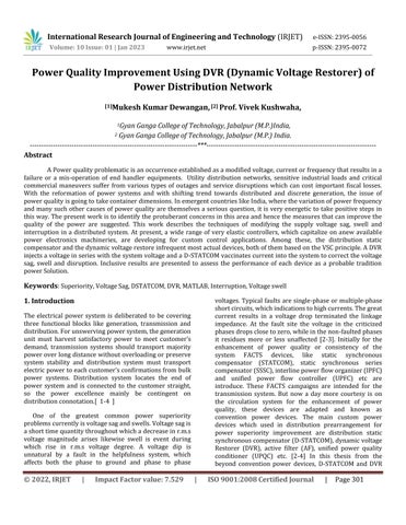
line voltage to critical loads during sags caused by unsymmetrical as well as regular three phase faults on adjacent feeders or disturbances that may originate many much away on the higher voltage unified transmission system. Connection to the delivery network is via three single-phase series transformers there by allowing the DVRtobeappliedtoallclassesofdistributionvoltages.At the point of joining the DVR will, within the limits of its inverter, provide a highly structured clean output voltage [7-9][15][19][23].
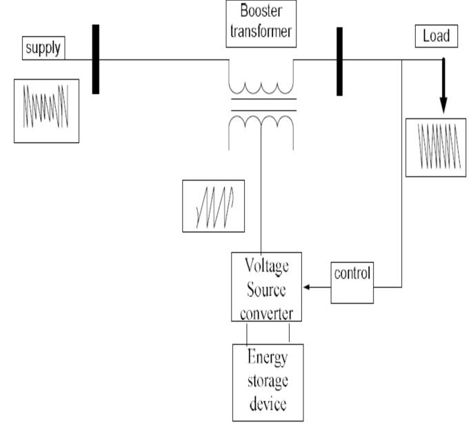
3.1 Basic Arrangement of DVR
The broad-spectrum prearrangement of the DVR involves of,
1.AnInoculation/Promotertransformer 2.ASungfilter 3.StoragePolicies 4.ACurrentSourceConverter(VSC) 5.DCchargingcircuit 6.AControlandFortificationsystem


3.2 Distribution Static Synchronous Compensator (DSTATCOM)
This chapter focused on the operating principles of DSTATCOM. The DSTATCOM is basically one of the traditionpowerdevices.ItisnonentitybutaSTATCOMbut used at the Spreading level. The key constituent of the DSTATCOM is a power VSC that is based on high power electronics technologies. The block diagram of DSTATCOMisshowninfigure-
The reactive power swapped between the DVR and distribution system is within generated by the DVR deprived of any ac passive reactive components, i.e. reactorsandcapacitors.Forlargedifferencesinthesource voltage,theDVRsuppliespartialpowertotheloadfroma rechargeable energy source devoted to the DVR dc terminal. The DVR, with its three single phase selfgoverning control and inverter design is able to restore
International Research Journal of Engineering and Technology (IRJET) e-ISSN:2395-0056
Volume: 10 Issue: 01 | Jan 2023 www.irjet.net p-ISSN:2395-0072
Fundamentally,theDSTATCOMsystemisincludedofthree main parts: a VSC, a set of connection reactors and a controller. The basic principle of a DSTATCOM connected in a power system is the generation of a controllable ac voltage source by a voltage source converter (VSC) connected to a dc capacitor (energy storage device). The circuit block digram of D-STATCOMis shown in figure 5.2, the ac voltage source, in general, appears after a transformer leakage reactance. The active and reactive power transmission between the power system and the DSTATCOM is initiated by the voltage metamorphosis across this reactance. The DSTATCOM is connected in shunt with the power networks at purchaser side, where the voltage-quality problem is a concern. All required voltages and currents are measured and are fed into the controller to be associated with the commands. The controller then makes feedback control and outputs a set of switching signals to drive the main semiconductor switches (IGBT’s, whichare used at the distribution level) ofthepowerconverteraccordingly[5].
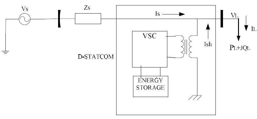
Figure4CircuitBlockDiagramofDVR
3.2.2 Principle of voltage regulation
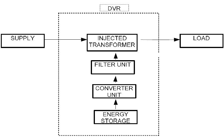
TheschematicdiagramofaD-Statcomisshowninfigure5 [5].
Figure5SchematicDiagramofaD-STATCOM


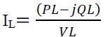
3.2.2.1
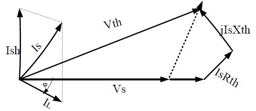
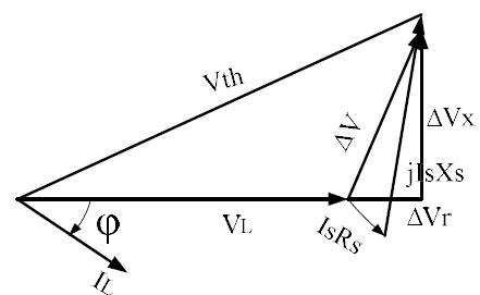
A simple phasor as shown in figure 5, it consists of a source voltage Vs, VL is the load voltage and load current IL. Without a voltage compensator the load voltage drop, produced by the load current IL. The change in load voltageisΔV.
International Research Journal of Engineering and Technology (IRJET) e-ISSN:2395-0056
Volume: 10 Issue: 01 | Jan 2023 www.irjet.net p-ISSN:2395-0072
ΔV=Vs
So, the voltage change has a essential ΔVr in phase with VthandelementΔVxhavinglaggingphasealteration[5].
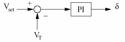
A controller is obligatory to control or to operate both DSTATCOM and DVR during the fault disorder only. Load voltage is detected and passed through a sequence analyzer. The magnitude of the actual voltage is likened with reference voltage i.e Vref. Pulse width modified (PWM) control system is every day for inverter transporting so as to engender a three phase 50Hz sinusoidalpowerattheloadterminals.


Now cogitate, a compensator connected to the system, Figure 7 shows and the vector diagram with voltage recompense.Byaddingacompensatorinparallelwiththe load, it is possible to supply energy equal to load voltage bycorrectingthepresent-dayofthecompensator[5].
Is=Ish+IL
International Research Journal of Engineering and Technology (IRJET) e-ISSN:2395-0056
Volume: 10 Issue: 01 | Jan 2023 www.irjet.net p-ISSN:2395-0072
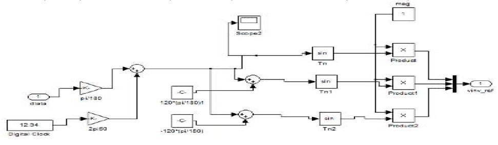
ThePhaseModulationoftheControlAngleisshowninfigure6.2.ThesinusoidalsignalVcontrolphasemoderatedbyincomes oftheangleδis,
VA=Sin(ωt+δ) VB=sin(ωt+δ-2π/3) VC=sin(ωt+δ+2π/3)
Figure9PhaseModulationoftheControlAngle


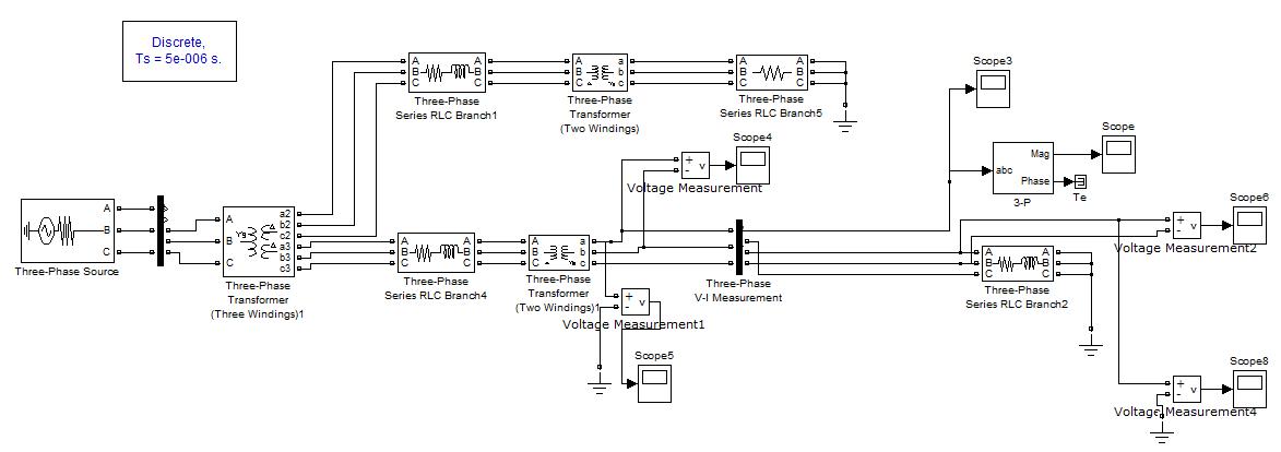
Figure10SimulinkModelofTestSystemwithoutFaultandWithoutDV
International Research Journal of Engineering and Technology (IRJET) e-ISSN:2395-0056
Volume: 10 Issue: 01 | Jan 2023 www.irjet.net p-ISSN:2395-0072
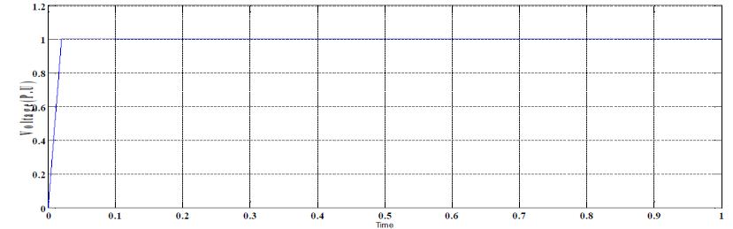
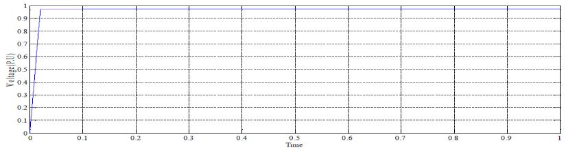
The RMS value of Voltage in p.u, instantaneous voltages, line to line voltage and phase voltage of the simulation result shown in the figure 11, 12,13 and 14 respectively, whenthesystemconsideringnofaultandnoconnectionof DVR. The line to line voltage is 11KV and phase voltage is 6.3508Vismeasured.
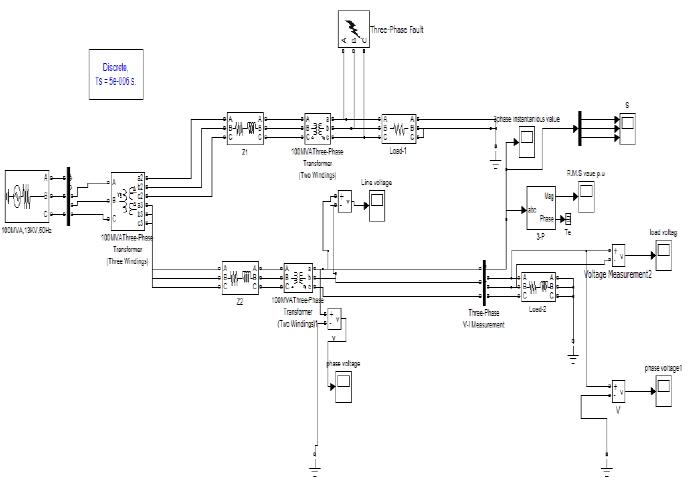
TheSimulinkmodelwithfaultdeprivedofDVRisshownin figure 15. In this Simulink model we have system which fedthetwobusesorfeedersovertwowindingtransformer as shown. On the upper bus we are smearing the 3phase Line to ground fault(3LG) , here we are not considering the presence of DVR and have to observe the result on currentsontheminorbus(anotherbusorsecondfeeder).
Figure11VoltageVrms(p.u)atLoadSide.
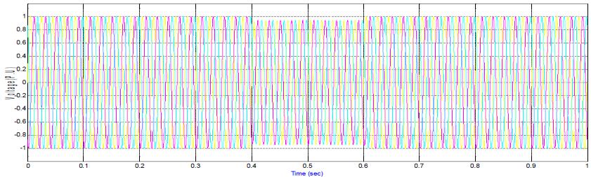
Figure12InstantaneousValuesinp.uatLoadSide.
Figure15SimulinkModelWithfaultDeprivedofDVR
Figure13LinetoLineVoltages(KV)atLoadSide
Figure14PhaseVoltage(KV)atLoadSide.
3.4.2
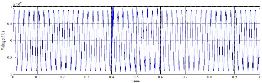
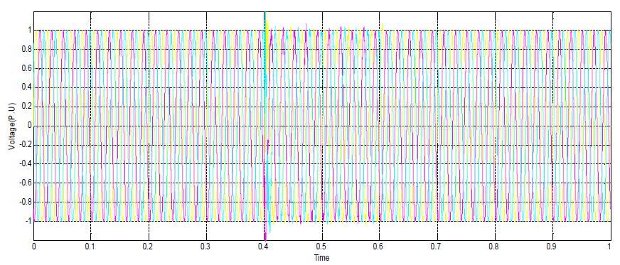
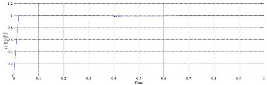
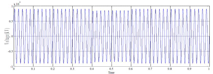
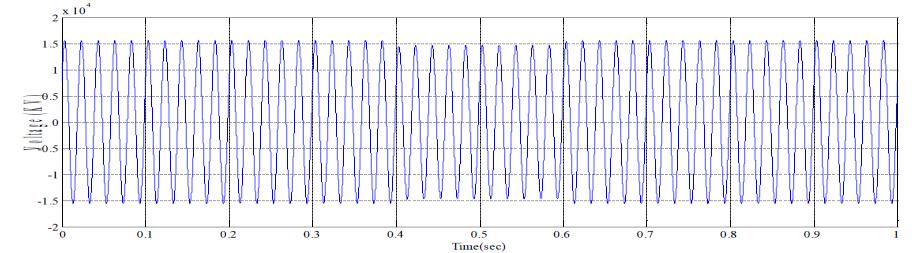
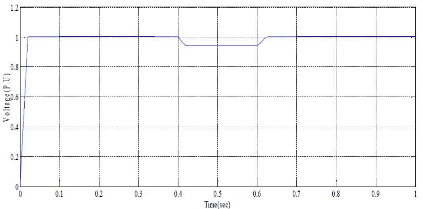
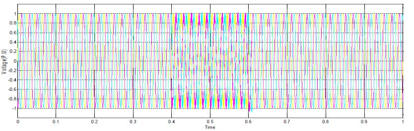
The simulation result showed in the figure 16,17, 18 and 19respectively.Fromthenextresultsitisexperientialthat during the fault time i.e 0.4-0.6 sec, the voltage sags to some finite value. Since the fault is on higher bus, hence sagmaybe70-80%.Thesagonthelowerbus attheload side is nearly 10-15%, and unhurried the line to line voltage value and phase voltage value during fault time is 10.1KVand6.01KV,respectively.
International Research Journal of Engineering and Technology (IRJET) e-ISSN:2395-0056
Figure16VoltageVrms(p.u)atLoadSide.
Figure17InstantaneousValuesinp.uatLoadSide.
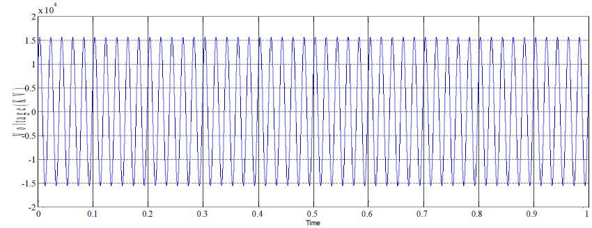
Figure18LinetoLineVoltages(KV)atLoadSide
Figure20SimulationTestSystemsforVoltageSwellwith DVR.
3.4.3.1 Simulation Results for Voltage Swell with DVR
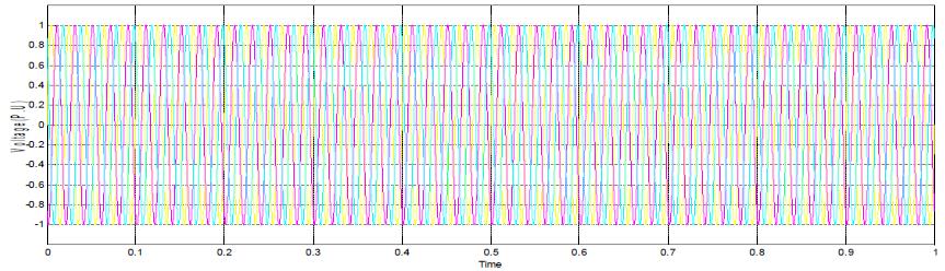
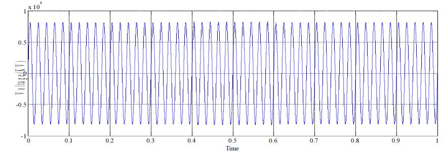
Fromthe resultsshown infigure21, 22, 23and24 shows thecompensatedresultsofswellwithrespectivermsvalue of voltage, instantaneous value, line to line voltage and phase voltages respectively, it is clear that the DVR compensate the voltage swell during the switching time 0.4-0.6second.
Figure19PhaseVoltage(KV)atLoadSide.
3.4.3 Simulation of Test System for Voltage Swells with DVR
The Simulation Test System for Voltage Swell with DVR is shown in figure 20. In the Simulink model we are considering the working of DVR to eliminate the swell duringthecapacitorswitching.
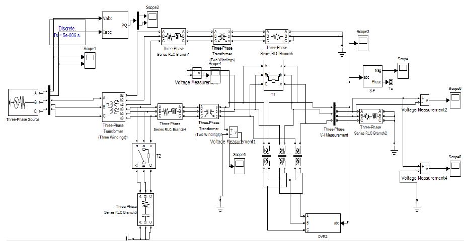
Figure21VoltageVrms(p.u)atLoadSide.
Volume: 10 Issue: 01 | Jan 2023 www.irjet.net p-ISSN:2395-0072 © 2022, IRJET | Impact Factor value: 7.529 | ISO 9001:2008 Certified Journal | Page308
Figure22InstantaneousValuesinp.uatLoadSide
International Research Journal of Engineering and Technology (IRJET) e-ISSN:2395-0056
Volume: 10 Issue: 01 | Jan 2023 www.irjet.net p-ISSN:2395-0072
3.5.1 Simulink Model of Test Scheme and Outcome
Simulation of test system deprived of fault and DSTATCOM the Simulink model of the test system without any fault and no connecting custom device like DVR is showninfigure26.
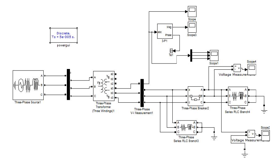
Figure23LinetoLineVoltages(KV)atLoadSide.
Figure24PhaseVoltage(KV)atLoadSide.
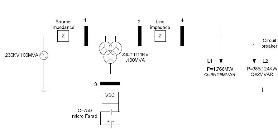
The test system comprehends of 230KV, 50Hz transmission line (measured to be source). This source, feedingtwodistributionnetwork throughathreewinding transformerconnectedinY/Δ/Δ230/11/11KV.Thesingle line diagram of the test system for D-STATCOM is shown figure25
Figure26DVRSimulationModel
3.5.2 Simulation Results without Fault and Without DSTATCOM
Theresultofthesystemwhenconsideringnofaultandno connection of D-STATCOM rms value of Voltage in p.u, instantaneous voltages, line to line voltage and phase voltage of the simulation result shown in the following figure 27, 28, 29 and 30 respectively. The line to line voltage and phase voltage are nearly11KV and 6.3508V is measured.
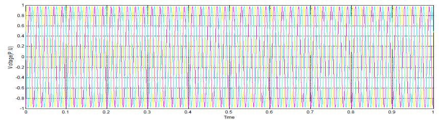
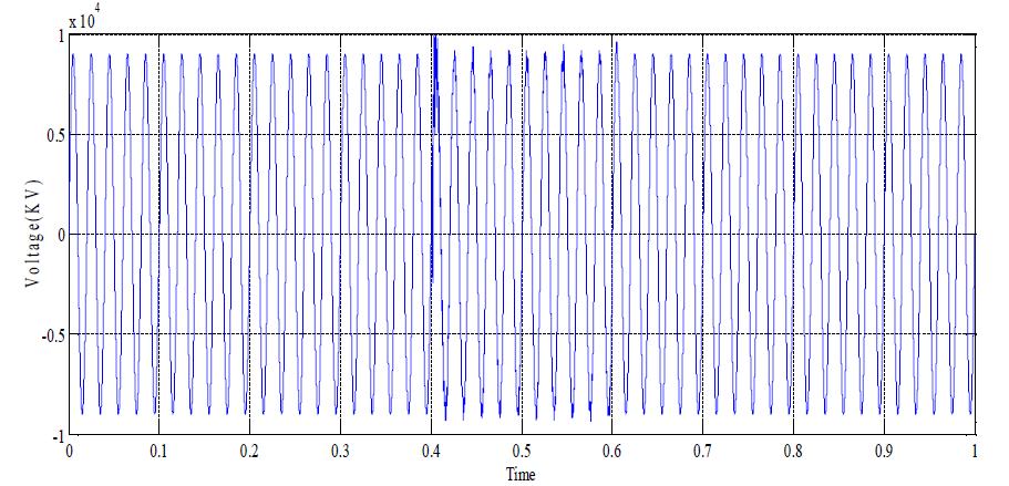
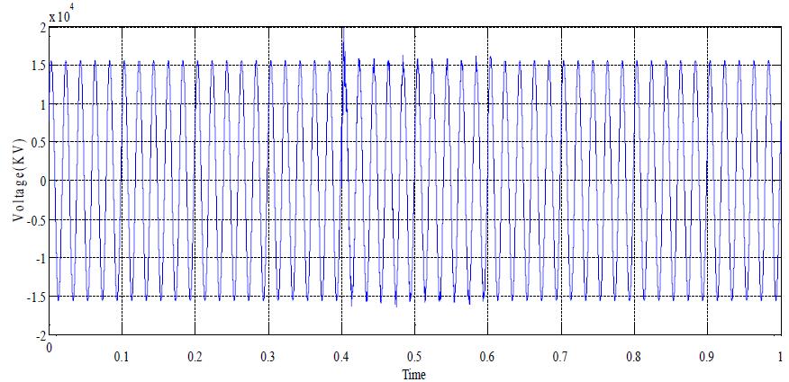
Figure27VoltageVrms(p.u)atLoadSide.
Figure25SoleLineDiagramoftheTestSystemforDSTATCOM
Figure28InstantaneousValuesinp.uatLoadSide.
International Research Journal of Engineering and Technology (IRJET) e-ISSN:2395-0056
Volume: 10 Issue: 01 | Jan 2023 www.irjet.net p-ISSN:2395-0072
Figure29LinetoLineVoltages(KV)atLoadSide.
Figure33RoutestoLineVoltages(KV)onLoadLateral
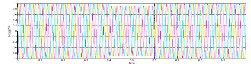
Figure34PhaseVoltage(KV)atLoadSide.
3.5.3 Simulation of Test System with D-STATCOM
Figure30PhaseVoltage(KV)atLoadSideways.
3.5.2 Replication Results with Fault but Deprived of DSTATCOM
Afterthesimulation the resultsshowninfigure31,32, 33 and34,itistrial thatthroughoutthefaulttime i.e.0.4-0.6 sec, the voltage sag to some limited value. The sag during the fault at the load side is nearly 10-15%, and measured the line to line voltage value and phase voltage value throughfaulttimeis10.25KVand6.01KVcorrespondingly.
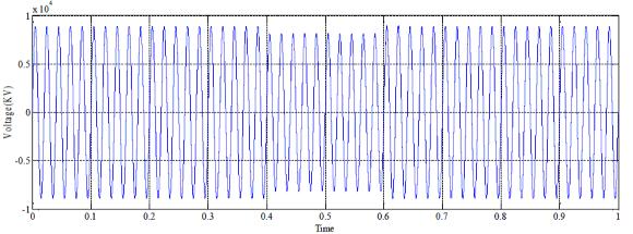
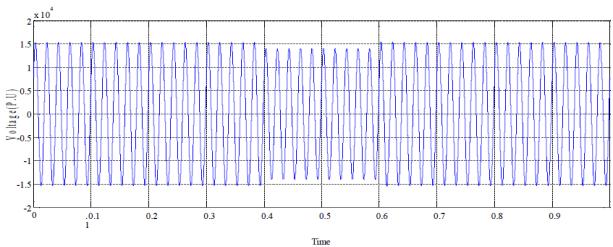
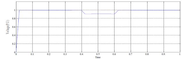
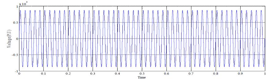
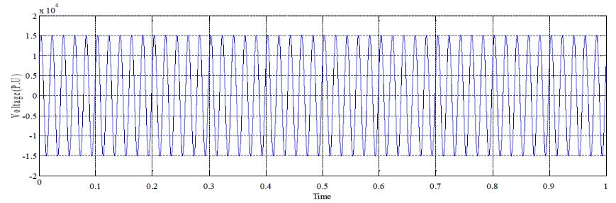
Figure31VoltageVrms(p.u)atLoadSide
The simulation exam system with D-STATCOM is exposed in figure 35. In this Simulink model we have structure which fed the load through secondary winding of tertiary transformer as shown. Out of two parallel loads, sag is createdbyprovidingtheSwitchingonsolitaryofload.The D-STATCOM is related to one of the secondary twisting of tertiarytransformer.
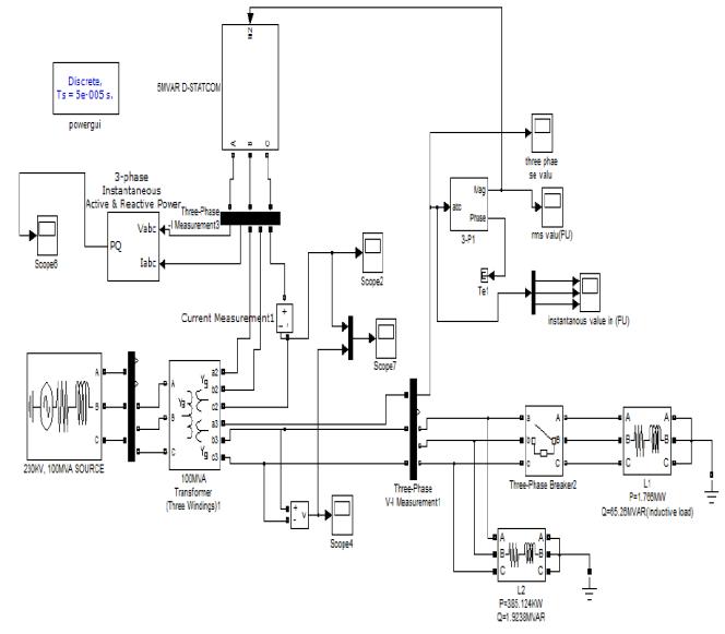
Figure32InstantaneousValuesinp.uatLoadSide
Figure35SimulationTestSystemswithD-STATCOM
International Research Journal of Engineering and Technology (IRJET) e-ISSN:2395-0056
Volume: 10 Issue: 01 | Jan 2023 www.irjet.net p-ISSN:2395-0072
3.5.4
Fromthesimulationresultsshowninfigure36,37,38and 39,itisclearthattheD-STATCOMcompensatethevoltage sag during the fault time 0.4-0.6 sec. the compensated resultsofsagwithrespectivermsworthofvoltage,prompt value, line to line voltage and phase voltages respectively. Thebatteryvoltageisfoundtobe28KV.
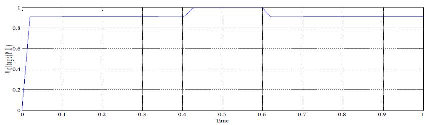
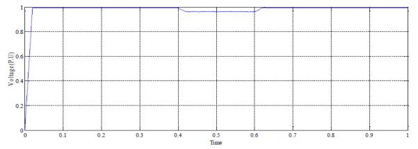
Figure36VoltageVrms(p.u)atLoadSide.
Thesimulationoftestsystemforvoltageswelldeprivedof D-STATCOM is shown in figure 40. The Simulink model representsthecreationofswellforthetime0.4-0.6sec.To create theswell switchisclosed for theinterval of 0.4-0.6 sec.
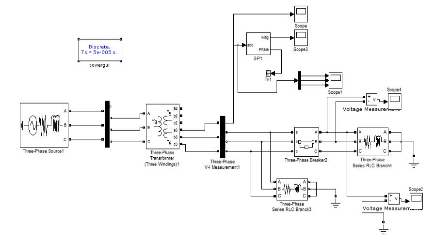
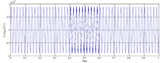
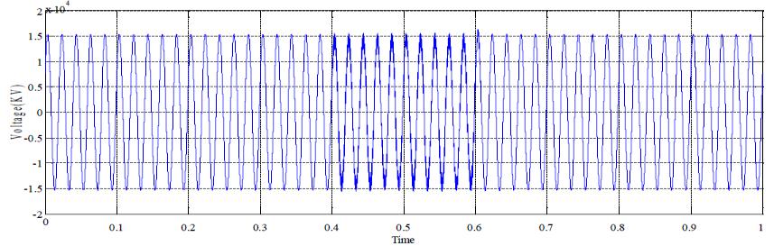
Figure37InstantaneousValuesinp.uatLoadSidewith FaultbutWithoutD-STATCOM
Figure40ReplicationofTestSystemforVoltageSwells DeprivedofD-STATCOM.
3.5.6 Replication Results for Voltage Swell deprived of D-STATCOM
Figure38LinetoLineVoltages(KV)atLoadSidewith FaultbutWithoutD-STATCOM
The voltage swell is created by closing the switch during 0.4-0.6 sec. The swell of 10-15% of its normal value is found at the interval of 0.4-0.6 sec, which is shown in the figure41,42,and43 representingrmschargeofvoltagein p.u, three stage instantaneous worth in p.u, line to line voltage and phase power in KV respectively. The line to line energy and phase voltage during the 0.4-0.6 are 0.93KVand0.588KVrespectively.
Figure39PhaseVoltage(KV)atLoadSidewithFaultbut WithoutD-STATCOM
Figure41VoltageVrms(p.u)atLoadSide.
International Research Journal of Engineering and Technology (IRJET) e-ISSN:2395-0056
3.5.8 Simulation of test system for voltage swells with D-STATCOM
Figure42InstantaneousValuesinp.uatLoadSide.
Fromthesimulationresultsshowninfigure,45,46,47and 48, it is clear that the DVR compensate the voltage swell during the switching time 0.4-0.6 sec. the compensated results of swell with respective rms value of voltage, instantaneousvalue,linetolinevoltageandphasevoltages respectively.
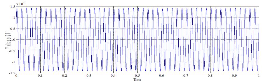
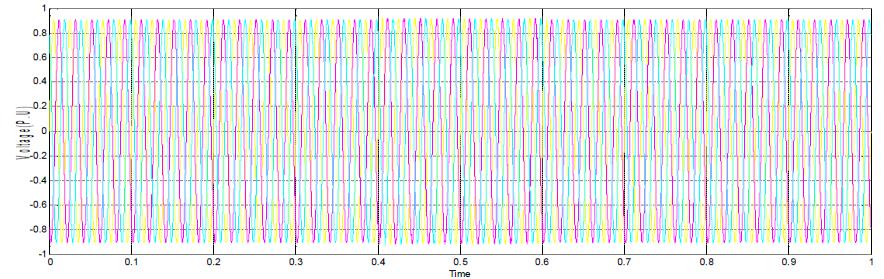
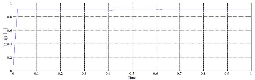
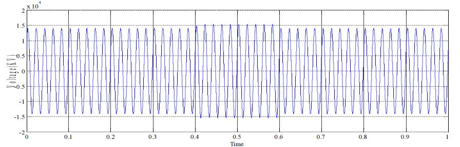
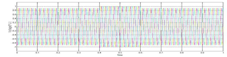
Figure43LinetoLinevoltages(KV)atLoadSide.
3.5.7 Simulation of Test System for Voltage Swells With D-STATCOM
The replication test system of voltage swell with Dstatcomisshowninfigure44
In the simulink model we are considering the working of D-STATCOM to eliminate the swell during the switchin of load.
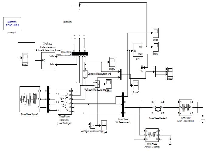
Figure45VoltageVrms(p.u)atLoadSide.
Figure44SimulationTestSystemsforVoltageSwellwith D-STATCOM
Figure46InstantaneousValuesinp.uatLoadSide.
Figure47LinetoLinevoltages(KV)atload
Volume: 10 Issue: 01 | Jan 2023 www.irjet.net p-ISSN:2395-0072 © 2022, IRJET | Impact Factor value: 7.529 | ISO 9001:2008 Certified Journal | Page312
International Research Journal of Engineering and Technology (IRJET) e-ISSN:2395-0056
Volume: 10 Issue: 01 | Jan 2023 www.irjet.net p-ISSN:2395-0072
sag and swell on 11KV feeder by means of both DSTATCOM and DVR as routine power devices and it has been found that DVR deliver excellent voltage regulation capabilities. It is also observed that the DVR volume for powerrecompenseandvoltageregulationdependsmainly on two influences that is, the rating of the dc storage deviceandcouplingtransformer.
Figure48PhaseVoltage(KV)atLoadSide.
Thisprojectreporthaspresentedthestudyandsimulation model of tradition power equipment, namely D-STATCOM and DVR, and applied them for power quality badlybehaved such as voltage sag and voltage swell. The highly grow graphic services available in MATLAB is used to conduct all the feature of typical implementation and to carryoutgeneralsimulationeducations.
A regulator which is based on closed loop method is used which generate error signals and this signals are used to trigger the switches of inverter using pulse width modulation (PWM) arrangement in the D-STATCOM and DVR, this PWM control scheme only requires voltage measurements. The simulations are passed out for both sagandswell on11KVfeederusingbothD-STATCOMand DVR as custom power devices and it has been originate that DVR provide outstanding voltage regulation capabilities. It is also observed that the DVR capacity for powerrecompenseandvoltageregulationdependsmainly on two influences that is, the rating of the dc storage deviceandthecouplingtransformer.
This project tale has presented the study and simulation model of tradition power equipment, namely D-STATCOM andDVR,andappliedthemforpowersuperiorityproblem such as voltage sag and voltage swell. The highly grow graphicamenitiesavailable inMATLABisusedtoconduct all the characteristic of model enactment and to transfer outwidesimulationtrainings.
A controller which is created on closed loop technique is usedwhichgenerateerrorsignalsandthissignalsareused to stimulate the changes of inverter using pulse width modulation (PWM) system in the D-STATCOM and DVR, this PWM control structure only requires voltage measurements. The simulations are carried out for both
[1] Reza Sedaghati, Navid Mehdizadeh Afroozi, Yaser Nemati, Ahmad Rohani, Ali Reza Toorani, Navid Javidtash, Ali Heydarzadegan, Hossein Sedaghati ““A Survey of Voltage Sags and Voltage Swells Singularities in Power Quality Difficulties” IJSRM, Volume 1, Issue 9, Pages 458462,2013.
[2] P. Venkata Kishore, Dr. S. Rama Reddy, “voltage sag mitigation in eight bus system using d-statcom for power quality improvement”, International Journal of EngineeringScienceandTechnology,Vol.2(4),2010,529537
[3] M.J.H.Bollen, “Voltage sags in three-phase scheme” Power Engineering Review, IEEE, Vol.21 Issue:9, Sept.2001.pp.8-11.
[4] N.G.Hingorani,”Flexible AC Transmission”, IEEE Spectrum,vol.30,pp.40-44,1993.
[5] Akil Ahemad,, Sayyad Naimuddin, ‘SIMULATION OF DSTATCOM IN POWER SYSTEM ‘ IOSR-JEEE -issn: 22781676,p-issn:2320-3331
[6] udechukwu chukwuemeka charles, “power quality analysis and mitigation”, universiti tun hussein onn malaysia,may2011
[7] shafzly a. mohammed1, aurelio g. cerrada2, abdelmoafmenm.a1,and b.hasanin, “dynamicvoltage restorer (dvr) system for compensation of voltage sags, state-ofthe-art review”, international journal of computational engineering research vol. 3 issue. 1, issn 22503005(online),january,2013page177
[8] s.v ravi kumar and s. siva nagaraju, “replication of DSTATCOM AND DVR in power systems” ARPN Journal of Engineering and Practical Sciences, VOL. 2, NO. 3, JUNE 2007 ISSN1819-6608
[9]sangeethas., vidyaj.,sathya,surajnayak&manasas., “modeling of d-statcom and dvr to enhance the power
quality “ Undergraduate Academic Research Journal (UARJ),ISSN:2278–1129,Volume-1,Issue-3,4,2012
[10] Parag Nijhawan, Ravinder Singh Bhatia and Dinesh KumarJain,“ApplicationofPIcontrollerbasedDSTATCOM for improving the power quality in a power system network with induction furnace load”, Songklanakarin J. Sci.Technol.34(2),195-201,Mar.-Apr.2012
[11] N.G.Hingorani, “Presenting Tradition Power”, IEEE Spectrum,vol.32pp.41-48,1995.
[12] Anaya-Lara O, Acha E., “Modeling and analysis of custom power system by PSCAD/EMTDC”, IEEE Dealings onPowerDelivery,Vol.17,andIssue:1,Jan.2002.Pp.266272
[13] H.P Tiwari and Sunil Kumar Gupta “Dynamic Voltage Restorer against Voltage Sag”,International of Innovation, ManagementandTechnologyvol.03,pp.232-237,2010.
[14] Arindam Ghosh, “Concert Comparision of VSC-Based Shunt and Series Compensators Used for Load Voltage Control in Distribution System”.IEEE Business on power distribution,vol.26,No.1,Jan,2011.Pp.268-278.
[15] Arindam Ghosh, “Copensation of Distribution System Voltage Using DVR”. IEEE Transaction on power delivery, vol.17,No.4,Oct.2002.Pp.1030-1036.
[16] C.S Chang, Y.S Ho, “The Effect of Motor Load on the Voltage Restoration Competence of Dynamic Voltage Restorer”. Power System Technology, Proceedings, Power Con,GlobalSession,vol.2,pp.637-642,2000.
[17]m.h. rashid,“power electronics”2nd edition, elsevier, inc,publication,californial,u.s.a2007.
[18] rakosh das begamudre, “extra high voltage ac transmission engineering”, 2nd edition, new age internationallimited,newdelhi1990
[19] majid moradlou and hamid r. karshenas, “design strategyforoptimumratingselectionofinterlinedvr”ieee, vol.26,no.1,jan,2011.
[20] ramesh c. kumhar , nitin sanadhya , prakash sundaram,pankajkumar, rajuswami,“solutionofpower qualityproblemsusing dstatcom”,ijltet
[21] rajan sharma and parag nijhawan, “role of dstatcom toimprovepowerqualityofdistributionnetwork withfoc induction motor drive as load”, global periodical of
International Research Journal of Engineering and Technology (IRJET) e-ISSN:2395-0056 Volume: 10 Issue: 01 | Jan 2023 www.irjet.net p-ISSN:2395-0072 © 2022, IRJET | Impact Factor value: 7.529 | ISO 9001:2008 Certified Journal | Page314
emergingtrendsinelectricalandelectronics(ijetee –issn: 2320-9569)vol.5,issue.1,july-2013.
[22] s.khalid & bharti dwivedi, “power quality issues, problems, standards & their effects in industry with corrective means”, ] international journal of advances in engineering & technology, may 2011, issn: 2231-1963, 1 vol.1,issue2,pp.1-11
[22] golla madhu1, chandra sreenivasulu2 , “modeling andsimulationofad-dstatcomforpowerqualityproblems based on sinusoidal pulse width modulation (spwm) by using fuzzy logic controller”, ijpres volume ii/issue 2/mar2014
[23] reena asati and dr. n.r. kulkarni, “a review on the controlplansusedfordstatcomanddvr”,globaljournalof electrical, electronics issn no. (online): 2277-2626 and computerengineering2(1):59-64(2013)
[24] t.devaraju, dr. v.c.veera reddy, dr. m. vijay kumar, “modeling and simulation of tradition power devices to mitigate power quality problems”, devaraju et. al. / international journal of engineering science and technologyvol.2(6),2010,1880-1885.
[25] tamal roy, mahesh singh, “pscad reproduction model of d-statcom for power sag development”, international journal of computer applications (0975 – 8887) volume 59–no.2,december2012
[26] s. suresh, n.devarajan, m.geetha,v. rajasekaran, “investigation on d-statcom operation for power quality improvement in a three phase three wire distribution system with a new control strategy”, control theory and informatics, issn 2224-5774 (print) issn 2225-0492 (online),vol1,no.2,2011.
[27] shaik khaja gareeb nawaz, shaik hameed, “mitigation of power quality problems by using dstatcom”, irdindia, issn (online): 2347-2812, volume-1, issue-3,2013
[28]rameshc.kumhar,nitinsanadhya,prakashsundaram, pankaj kumar, raju swami, “solution of power quality problems using dstatcom”, international journal of latest trendsinengineeringandtechnology(ijltet),vol.2issue4 july2013
[29]maheshsingh,vaibhavtiwari,“modelinganalysisand solutionofpowerqualityproblem.