A Fuzzy-PI based Gain Optimizing Approach for Speed Controlling of DC Motor
Anshul Soni1 , Deepak Bhataniya22Assistant Professor, Department of Electrical and Electronics JIT Borawan, Khargone(M.P) INDIA

Abstract - In areas demanding flexible and smooth speed torque characteristic, DC motor drives are very popular. Its small size (in comparison with other motors of same rating), high torque density and better efficiency makes it more prevalent. This variation is speed is according to the demand of load connected. Thus, this requires a system, which automatically adapts to this point inshortmakingsystemvery vital for engineering and science. In this work,thefocuswillbe to develop a model based on two techniques called PID controller and Fuzzy logic based intelligent controller. The fuzzy controller is comprised of a human-like intuition strategy with the help of membership function and rule base. The design and implementation are done on MATLAB platform. In this work, the comparison is done over the performance of two controllers for DC motor basedonsettling time, rise time, peak time, and percent overshoot. The inputs taken for modeling the fuzzy logic modelareerrorandchange in error and the single output to the model will be required signal for motor speed control. Based on the signal, the input supply is regulated for speed control of DC motor.
Keywords– Speed Control of DC Motor, Fuzzy logic controller, PID Controller Tuning, rise time, Peak overshoot, Peak time.
1. INTRODUCTION
In the past century, the electric motor has played a major roleinindustrial development.Severaltypesofmotorare developedbasedontherequirement.Eveninthedomestic application,motorshaveabigroletoplay.Severaltypesof appliances like AC, Refrigerators, fans, etc. uses electric motors only. Every industrial process demands a variable speedoperationfromthemotorbasedontherequirement fromtheload.Hence,tofulfillthatdemandacircuitistobe designed to control the speed of the motor, known as an electric drive. Out of all type drives, the DC motor is very popularduetoitssimpleandefficientoperationalongwith goodcontrolcharacteristicscomparetotheinductionmotor.
In the present electrical framework pressure from governmentregulationsandreductioninoperationalcosts are high. The system demand that the framework is independent of electromagnetic obstruction and good productivity.OnesuchactivityisspeedcontrolinDCmotor. Any DC motor drive needs to have minimum possible transients’generationwhichcontrollingspeed.Usually,the
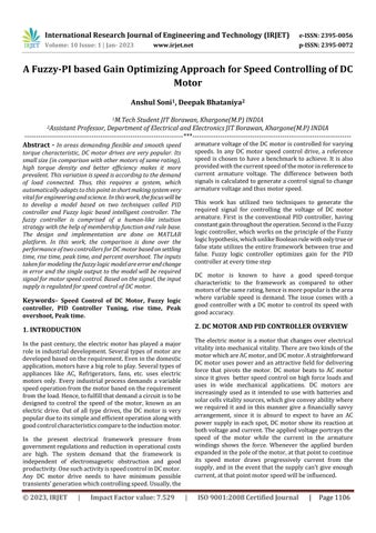
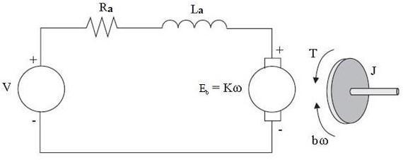
armaturevoltageoftheDCmotoriscontrolledforvarying speeds. In any DC motor speed control drive, a reference speedis chosen to have a benchmark toachieve. It isalso providedwiththecurrentspeedofthemotorinreferenceto current armature voltage. The difference between both signalsiscalculatedtogenerateacontrolsignaltochange armaturevoltageandthusmotorspeed.
This work has utilized two techniques to generate the required signal for controlling the voltage of DC motor armature. First is the conventional PID controller, having constantgainthroughouttheoperation.SecondistheFuzzy logiccontroller,whichworksontheprincipleoftheFuzzy logichypothesis,whichunlikeBooleanrulewithonlytrueor falsestateutilizestheentireframeworkbetweentrueand false. Fuzzy logic controller optimizes gain for the PID controllerateverytimestep
DC motor is known to have a good speed-torque characteristic to the framework as compared to other motorsofthesamerating,henceismorepopularisthearea where variable speed is demand. The issue comes with a good controller with a DC motor to control its speed with goodaccuracy.
2. DC MOTOR AND PID CONTROLLER OVERVIEW
The electric motor is a motor that changes over electrical vitalityintomechanicalvitality.Therearetwokindsofthe motorwhichareACmotor,andDCmotor.Astraightforward DCmotorusespowerandanattractivefieldfordelivering force that pivots the motor. DC motor beats to AC motor sinceitgives betterspeedcontrolonhighforceloadsand uses in wide mechanical applications. DC motors are increasingly used as it intended to use with batteries and solarcellsvitalitysources,whichgiveconveyabilitywhere werequired it and in this manner give a financially savvy arrangement, since it is absurd to expect to have an AC power supply in each spot, DC motor show its reaction at bothvoltageandcurrent.Theappliedvoltageportraysthe speed of the motor while the current in the armature windings shows the force. Whenever the applied burden expandedinthepoleofthemotor,atthatpointtocontinue its speed motor draws progressively current from the supply,andintheeventthatthesupplycan'tgive enough current,atthatpointmotorspeedwillbeinfluenced.
By and large, it tends to be said that applied voltage influencesspeedwhileforceiscontrolledbythecurrent.DC motors give progressively compelling outcomes if the cleavingcircuitisutilized.LowpowerDCmotorordinarily useinliftingandtransportationpurposesaslowpowerAC motorsdon'thavegreatforceability.DCmotorisutilizedin railroad motors, electric vehicles, lifts, automated applications, vehicle windows, and a wide verity of little machinesandcomplexmodernblendingformswhereforce can'tbeundermined.
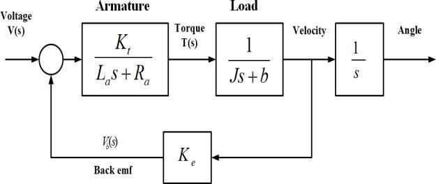
ThereareafewkindsofDCmotorhowevermostnormalare brushedDCmotor,brushlessDCmotor,steppermotor,and servo motor. These DC motors have three winding procedures,forexample,shuntDCmotor,arrangementDC motor,andcompoundDCmotor.
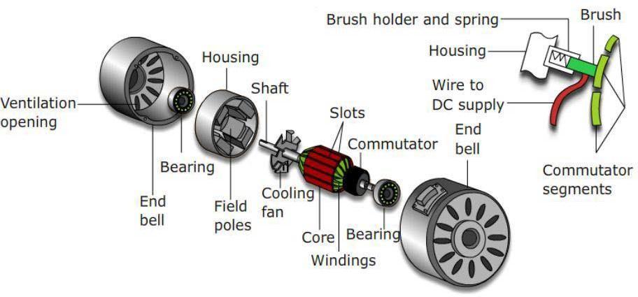
IthasbeendevelopedinMATLAB/Simulinkasshown
Everymachineisprompttowardsdynamicsystems.Having a controller is very important for maintaining stability. Several conventional methods proposed in past, some of whicharelisted1)Classicalcontrolmethodslikerootlocus design,lead-lagcompensator,etc2)Nonlinearmethodslike back-stepping,Lyapunovredesign,etc3)Controlmethods having an adaptive property like self-tuning regulators, dynamicprogramming,etc
All such controllers have a property to utilize the data mathematicalmodeloftheprovidedsystem.Eachcontroller is required to have a self-tuning capability of the system. Suchamethodismoreimportantbecauseofthefactthatthe mathematical model designed is not always accurate as dependsupontheparameterschosentodesignit.Heuristics isonesuchproblemariseswithallconventionaltechnique anditdoesn’tfitintothepropermathematicalframework whichmighthelpinpropercontrolling.
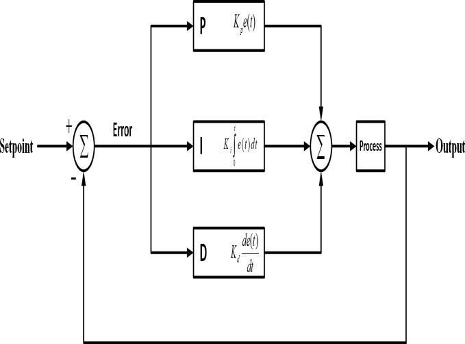
OutofconventionalmethodsPIDcontrollersfindapplication in speed controlling of DC motor. PID stands for Proportional, Integral, and derivative modes of control. A combination of these three different modes is utilized in many systems. In the following section discusses three modesindetail
The proportional controller mode is usually useful under conditionswhensuddenlychangeinthesystemhappened. “P”controllerislinearinnaturehenceitsresponseisvery fast.Thiscontrollerfindsdifficultyinstabilizingthehigherorderprocesshencecanbeeffectivelyusedforsingleorder processesonly.Suchaprocesssystemiscomprisedofonly oneenergystoreelement.Hencethesystemcanwithstand largegainincrementwhichfurtherleadstolowsteady-state error.Alowsteady-stateerrormeansthesystemisfollowing theoutputpatternoftheprocessefficiently.Also,largegain gives a fast response, as discussed earlier means process controlwillbeverysensitiveinaclosed-loopsystem.Also, proportionalgainhelpsinattainingsmalleramplitudesand phasemargin
Integral controller mode comes handy when the present stateofthedynamicprocesssomehowdependsonthevalue ofthepaststateofthesystem
HenceacombinationofP&IcalledPIcontrollertofindsthe better application. The benefit of PI is that it will remove forced oscillation in the system that occurred due to switching in the system. Although there is also a certain drawbackofthePIsystem,onemajoroneiscompromised withspeed.TheresponsespeedofPIbisslowerthanthatof Pandalsohaveanegativeeffectonoverallstability.
Bothintegralandproportionalmodesofthecontrollerhave no ability to predict the nature of the error in the near future.Thisledtotherequirementofacontrollerwhichcan provideinformationregardingvaluesoferrorinthefuture for a dynamic system, which is fulfilled by the derivative controller. Derivative modes have the ability to find the solution to gain whose value is dependent on the future error value. Again, in order to avoid sudden variation in output due to sudden variation in input combination of proportionalandderivativeisused.Suchasystemfindsits applicatio0ninareaslikesubmarines,ships,flyingvehicles. Whenallthemodesareusedsimultaneouslyinanydynamic systemitiscalledaPIDcontroller. Thecontrollershelpin estimating control inputs of the system by adjusting gain accordingtosystemerrorpattern.
PIDcontrollercanachievequickresponsewiththehelpof derivative mode. Reduction in error towards zero using integral control mode and reduction is oscillation using proportionalmode.Suchacontrollerisusedwiththeorder of the dynamic system is more than 1st order. Such a controllerisusedinanareawherehighprecisionisrequired like Autopilot in Airplanes. proportional, integral, and the derivativetermisgivenby:
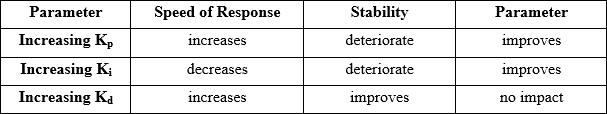
Table-1 EffectsofCoefficients
2.3 PID TUNING METHODS
Everydynamicsystemhasitsownbehaviorandeachsystem hasitsownrequirementwhichdependsontheadjustment ofcontrolparameterstothebestpossiblevalue.Tuningis thustheprocessoffindingthemostoptimalvalueofgainof 3modessuchthatsystemcontrollingcanhappenalongwith maintainingstability.Differentmethodsaretherefortuning, some of them are manual tuning and PID tuning software method.
Themanualtuningmethodasthenamesuggestsworksby changingvaluesofKp,Ki&Kdtillthedemandforcontrolis obtained.It'slikethehit&trialmethod.Stepstofollowwhile finding optimal gain value is to set the value of Kp is increased until the output of the system start oscillations. The value of Kp is exactly half of the above point. After setting
Kp, the value of Ki increased until the error is settled insufficient time until the system becomes unstable. After setting Ki, the value of Kd is increased until the system steady- state error is reduced to acceptable value with havingasystemovershoot.
In the PID tuning software method, the gain is optimized withthehelpofanytheoreticalmethodimplementedwith the help of any software. In this work, we have used both thesemethods,foroptimizinggain.Inthesoftwaretuning method,wehaveusedthefuzzylogicapproachinMATLAB software.
In the year 1965, the fuzzy logic approach was first proposed,butitwasintheyear1974whenfuzzylogicwas firstusedinanypractical application.ItwasDr.Mamdani (basedonwhomMamdaniapproachofFLCisnamed)used Fuzzylogicincontrollingofthesteamengine.Sincethenthe popularityofafuzzylogicideahasgainedpaceandnowit finds application in each sector of society ranging from automobiles,industrialmanufacturingandhospitals,etc.in order toimplementfuzzy logicthree-stageoperationsare performed.Itstartswithfuzzificationthenfuzzyinference process&defuzzification.
Anyfuzzysetcanbeexpressedinthefollowingway
µ��(��) �� [0,1]
Wherexisanyset,Aisanymemberofthatset,µ�(�)isthe membership function. Now similar to classical set theory fuzzyalsoexhibitanalmostsimilartypeofoperations.Letx &yaretwofuzzysetselement
2.4 STEP RESPONSE CHARACTERISTICS
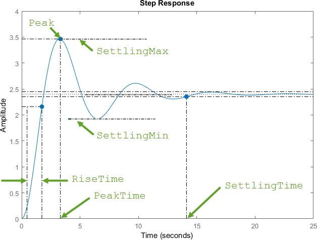
In order to understand the behavior of any system, step response characteristics are used. In such an analysis, the output of the system is an observer for a change in input from0to1inaveryshorttime
Union:������ = µ��(��) �� µ��(��)
= max (µ��(��), µ��(��))
Intersection:�� Ո �� = µ��(��) Ո µ��(��)
= min (µ��(��), µ��(��))
Compliment:���� = ��/��
2.6 INTRODUCTION TO FUZZY LOGIC CONTROLLER
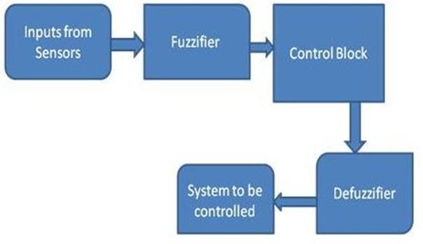
Anyfuzzylogiccontrollerperformsthreemaintasksnamely Fuzzification, Decision using control block, and defuzzification.Thefollowingblockdiagramshowsthesteps involvedinFLC.
Fig-7:StepResponseCharacteristic
2.5 FUZZY LOGIC THEORY
Fuzzylogicisamathematicalsystemthattakesinputinform ofcrispvalueandperformstheoperationusingequivalent linguisticterms.Basically,fuzzylogicisbasedonthewaythe human brain behaves, where its decision is based on feelings.Thewaythehumanbraintakesadecisionbasedon past learning experiences is now replicated in fuzzy logic theory.
2.7 FUZZY CONTROL RULES
In order to gain knowledge like a human being, rules are formed in a fuzzy interface system with the help of the expert opinion of human beings. Such rules are based on input&outputwiththehelpoftheIF-THENcondition.Rules basehelpindevelopinganalgorithmtogiveoutputforany
particularinputvalue.TheseruleshelpFIStocalculatethe degreethei/pmatchestheconditionofarule.Theprocess of forming rules can be done in two ways. In the first mapping between i/p &o/p isdone withlinguistic terms. Whereas in a second way, logic is formed to find the relationshipbetweeni/p&o/p.
2.8 DIFUZZIFICATION
Theprocessistheoppositeoffuzzification.Postfis,theo/p generatedisintheformoflinguisticorvagueform.Inorder toutilizeintheapplication,itneedstobeconvertedbackto crispo/p.Severalmethodsarepossiblefordefuzzification. someofthemarediscussedbelow.
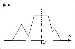
Mean of maximum (MOM) method: in this method, the outputvalueisequaltotheaveragevalueofoutputwiththe highestdegree.TakingexamplesofACagainiftheo/pFISis “SLOW” then the crisp value from the defuzzifier can be givenbythefollowingequation.
MOM(SLOW) =
Wherepstandsforasetofo/pxwithamaximumvalueof MFforo/pSLOW.
3.1 FLOW CHART FOR SPEED CONTROL OF DC MOTOR USING FLC
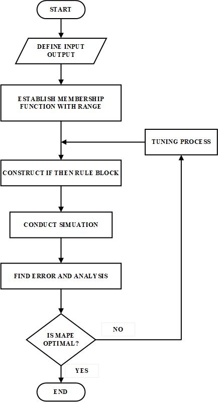
Thebelowfigurerepresentsthestepsinvolvedincontrolling thespeedoftheDCmotorusingthefuzzylogiccontroller. Theworkstartswiththedefinitionofinputsandoutputsfor the given problem. Now each of these inputs and outputs mustberepresentedintheformofrespectivemembership functionwithdifferentrangeanddifferentwidthofdifferent categories,makingeachmembershipfunctionuniqueforthe particularinputparameter.
Afterdefiningthemembershipfunctionthenextstepisto develop arulebaseusingknowledgebasebyexpertopinion. These rules are defined based on an if-then conditional statement.Oncetheserulesareformedasimulationisdone basedoninputandoutputdata.Basedonthisdataerroris calculated on forecasted and actual value of the output parameter. After the evaluation of error, a comparison is donewiththerequiredoptimumerrorvalue.Ifthetargetis reachedthennofurthertrainingisrequiredandtheprocess willend,otherwise,furthertuningoftheprocessisdoneto improvetheresultandthesamestepsarefollowedagain.
3.2 VARIABLES USED
TheLinguisticVariablesconsideredinthecontrolare
Z-Zero
PM-PositiveMedium
NM-NegativeMedium
PL-PositiveLarge
NL–NegativeLarge
Wehaveconsidered5Linguisticvariables(NL,NM,ZE,PM, PL)fortheInput‘Error’andonly2Linguisticvariables(NL, PL) for the Input ‘Rate of Change in Error’. In the case of Output‘Control’,wehaveconsidered5Linguisticvariables (NL,NM,ZE,PM,andPL).
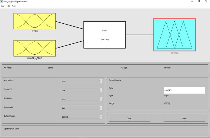
3.3 MEMBERSHIP FUNCTIONS USED
TheinputsareErrorisspeedandChangeinError.Wehave studiedabovetheFuzzyrulebaseandformedtherulesfor5, 2linguisticvariablesoftheinputsand5linguisticvariables of the output using the Fuzzy toolbox. The membership functionsusedare
ErrorSignal–2trapezoidaland3triangular.
ChangeinErrorsignal–2triangular.
Controlsignal–5triangular
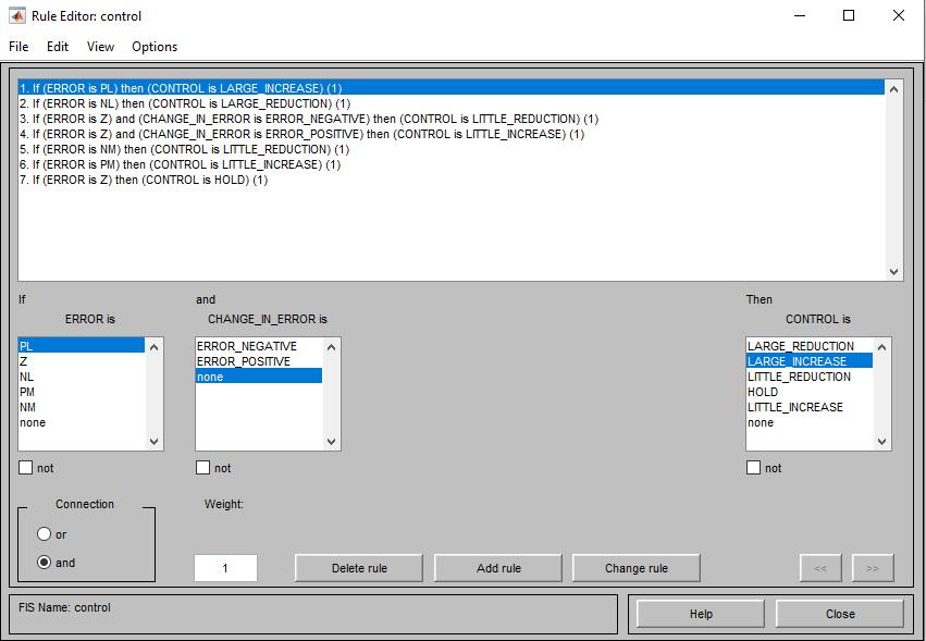
3.4 FUZZY RULE BASE
GeneralInterpretationofthecontrol rulestobesettothe Fuzzycontrol:
IfError=0andChangeinerror=0,thendonotchangethe presentsetting.
If Error is non-zero but Error is tending to zero at an acceptablerate,thendonotchangethepresentsetting.
IfErrorisincreasingordecreasing,thenmakethecontrol signalaccordingtothemagnitudeandsignoftheErrorand ChangeinErrortomaketheError=zero.
4. RESULTS
The Simulink model is prepared for two techniques, and their results obtained are shown and discussed in detail. PostmathematicalmodelingofDCmotor,itisimplemented inSimulink.ThemodeloftheDCmotorremainsthesamefor both the controllers. The controllers are then designed in Matlab/Simulink software. Both the Fuzzy and PID based model’soutputisdisplayedandcomparedtofindthebest outoftwobasedonspeedsignalresponseparameters
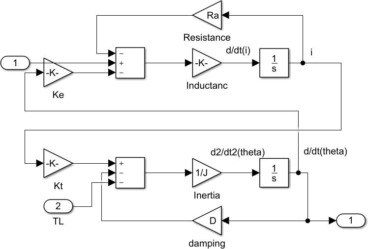
The model comprises four factors of DC motor they are Armature Resistance, Armature Inductance, Inertia, and dampingcoefficient.
Rated Speed = 1500 rad/sec., Back EMF constant = 0.01 V/rad/sec , Reference Speed = 1450 rad/sec. and Load Torque=10N-m.
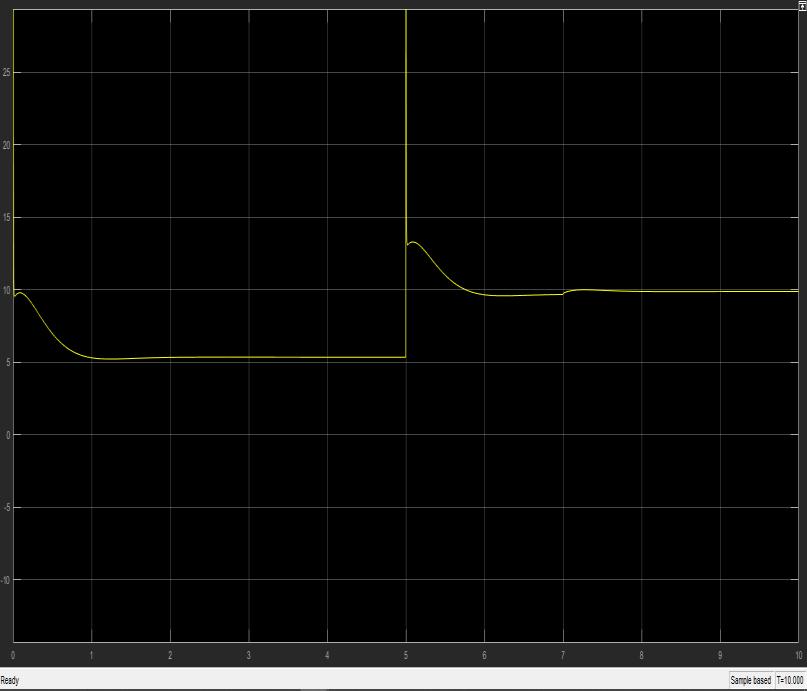
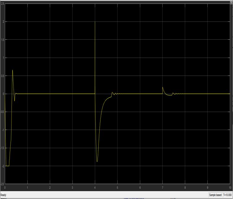
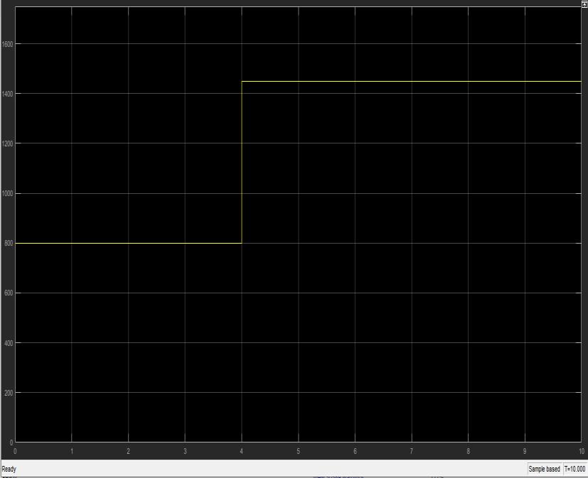
Theabovefigure15showsthemodelofthePIDcontroller. Thereferencespeedwassetto800forthefirst5secandto 1450forthelast5sec.Thereferencespeedisnormalizedto perunitvalue.Thisvalueisthensubtractedwiththepresent outputvalueofthespeedoftheDCmotor,givingerror.The value of the error is fed to the PID controller, which generatedtheappropriatesignaltoreducetheerrorvalue and control the speed of the motor. The response of the motor based on the controller is noted and shown in the followingfigures
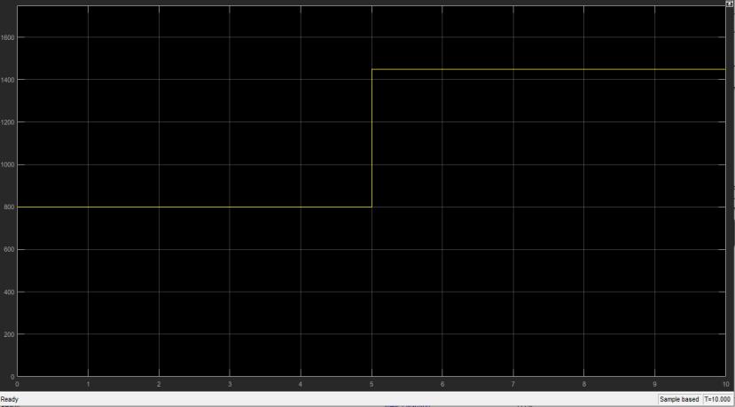
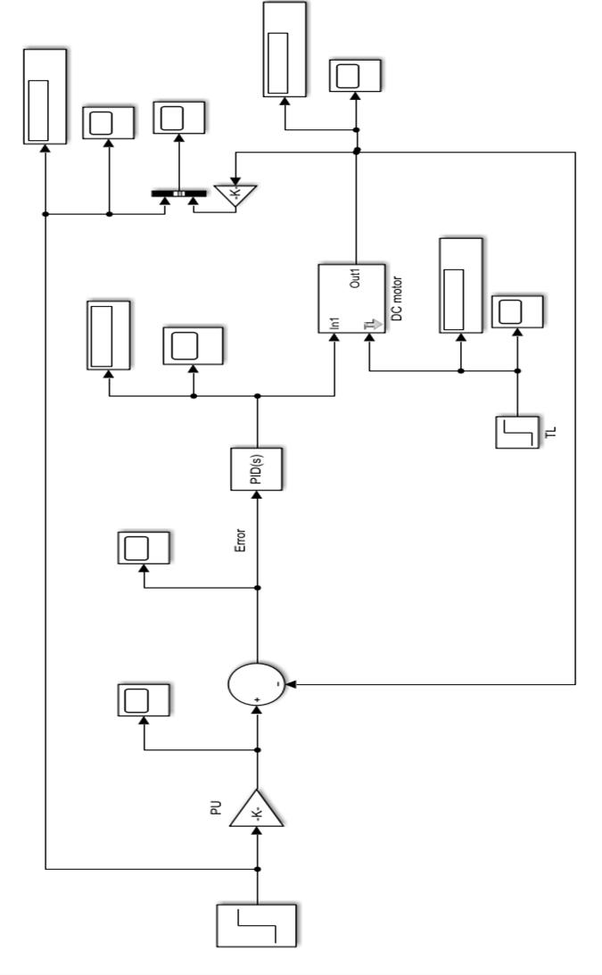
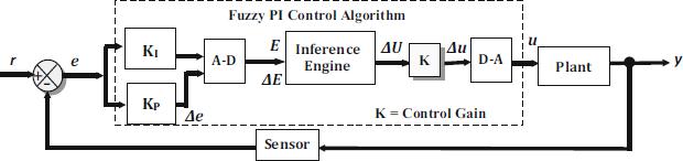
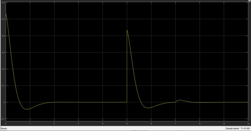
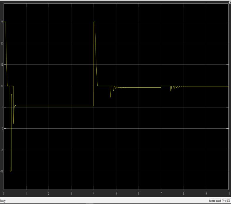
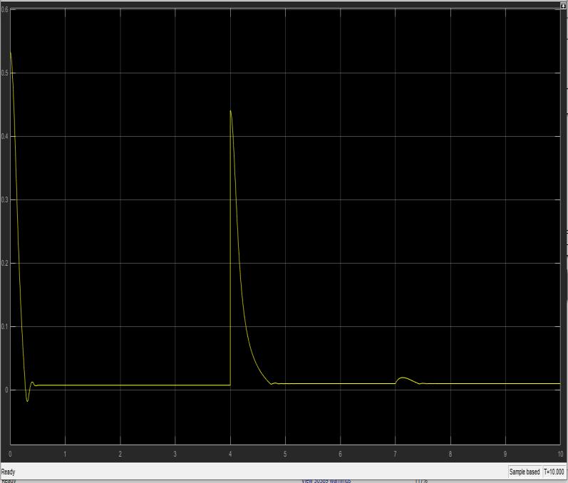
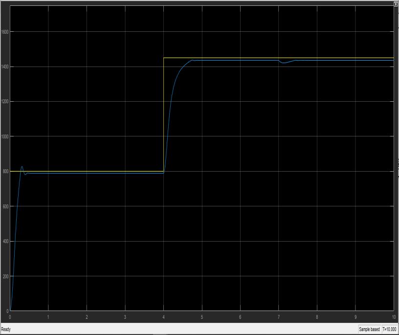
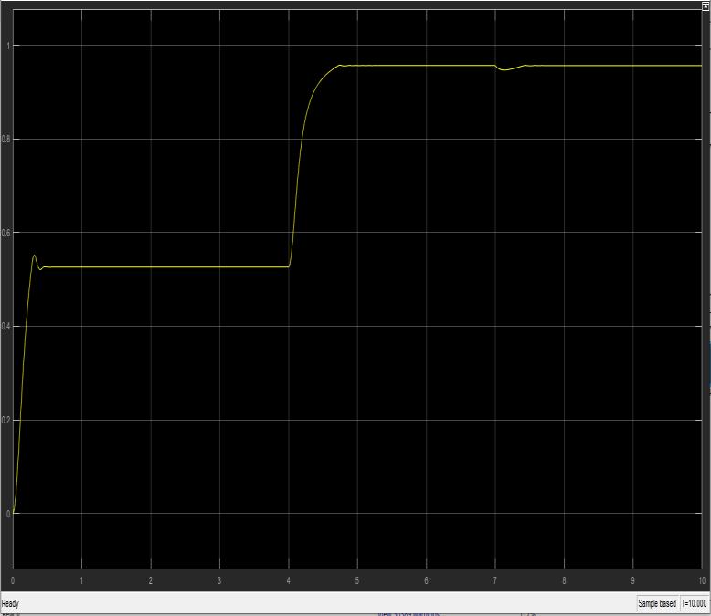
Figure20showsthemodeloftheFuzzylogiccontroller.The referencespeedwassetto800forthefirst5secandto1450 forthelast5sec.Thereferencespeedisnormalizedtoper unitvalue.Theadvantageofper-unitvalueisthatitmakes designing a range of variables for membership function in theFuzzylogictoolboxeasy.Thisvalueisthensubtracted withthepresentoutputvalueofthespeedoftheDCmotor, giving error. The value of error is further differentiated usingaderivativeblocktogetachangein errorvalue.The value of error and change in error is fed to the Fuzzy controller block as inputs, which then generated the appropriatesignaltoreducetheerrorvalue based on the rule base. This output value is then subtracted with armaturevoltagetocontrolthespeedofthemotor.
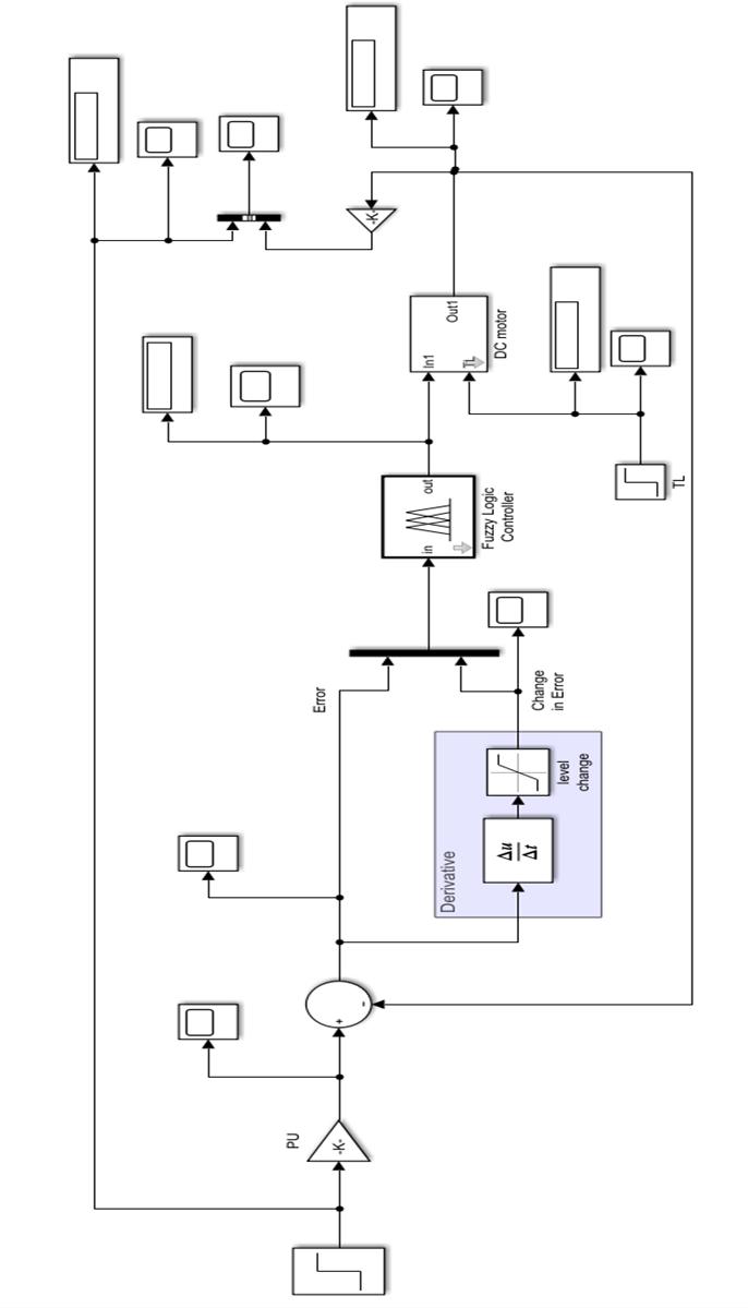
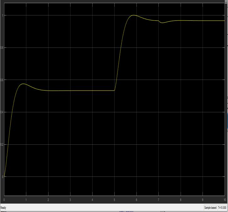
Theresponseofthemotorbasedonthecontrollerisnoted andshowninthefollowingfigures.Theinitialloadtorque (TL)takeninthepresentcaseis0.0001N-mand0.002N-m asthefinalvalueofloadtorqueafter7sec.Thevalueofthe fuzzylogicoutputsignalandLoadtoqueisfedasinputtothe motor model, which will giveperunitvalue ofspeed. The speed is then multiplied with inverted gain as taken with referencespeedgainblocktogettheactualvalueofspeed.
4.3 SPEED RESPONSE PARAMETERS FOR PID AND
FUZZY CONTROLLER
Table-2speedresponseparametersforPIDController
RiseTime: 5.2730sec
SettlingTime: 6.2274sec
SettlingMin: 1305.1m/sec
SettlingMax: 1501.3m/sec
Overshoot: 3.5366rad/sec
Undershoot: 2.237210^-05rad/sec
Peak: 1501.3m/sec
PeakTime: 5.8704sec
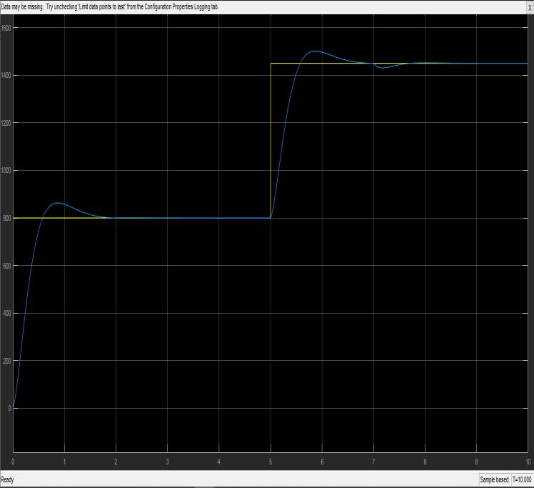
Table-3speedresponseparametersforfuzzycontroller
RiseTime: 5.2030sec
SettlingTime: 5.5475sec
SettlingMin: 1291.6m/sec
SettlingMax: 1436.5m/sec
Overshoot: 0.0916rad/sec
Undershoot: 1.044310^-04rad/sec
Peak: 1436.5m/sec
PeakTime: 5.7453sec
5.CONCLUSION
Inthiswork,basedonthemathematicalmodelingoftheDC motor,theSimulinkmodelofDCmotorisbeensuccessfully designed.Differentcontrollersarestudiedforcontrollingthe speedoftheDCmotor.OutofwhichPIDhasstoodoutasa conventionsolution.Wehavealsostudiedandunderstood various concepts of Fuzzy logic and Fuzzy set theory. The fuzzylogiccontrollerisproposedasabettersupplementto PID.Afterthat,bothcontrollersaredesignedandconnected with the above DC motor model in Matlab/Simulink successfully. The simulation is performed on both models separatelyandtheirresultsareobtainedandsummarized. On comparing results in table 2 and table 3 it is clearly
evident that Fuzzy logic-based controllers are better performingthanPIDbasedcontrollerbecauseithasalow valueofrisingtime,peaktimeandsettlingtimeandalsohas asmallvalueofovershoot.
REFERENCES
[1]TigoWati1,Subiyanto1andSutarno,“Simulationmodel of speed control DC motor using fractional order PID controller”, Journal of Physics: Conference Series, Volume 1444,Number1,IOPPublishingLtd,2020
[2] Suresh Kumar B., Varun Raj D., Venkateshwara Rao D, “SpeedControlofBLDCMotorwithPIControllerandPWM Technique for Antenna’s Positioner”, Emerging Trends in Computing and Expert Technology, COMET 2019, Lecture Notes on Data Engineering and Communications Technologies,vol35,Springer,2019.
DOI:https://doi.org/10.1007/978-3-030-32150-5_43
[3]Farahani,G.,Rahmani,K.,“SpeedControlofaSeparately Excited DC Motor Using New Proposed Fuzzy Neural Algorithm Based on FOPID Controller”, Journal Control Autom Electrical System 30,pp728–740,2019.
DOI:https://doi.org/10.1007/s40313-019-00485-8
[4] N. L. Ismail, K. A. Zakaria, N. S. Moh Nazar, M. Syaripuddin,A. S. N.MokhtarandS.Thanakodi,“DCmotor speedcontrolusingfuzzylogiccontroller”,AIPConference Proceedings1930,2018.
DOI:https://doi.org/10.1063/1.5022920
[5]JesúsU.Liceaga-Castro,IrmaI.Siller-Alcalá,JorgeJaimesPonce,RobertoA.Alcántara-RamírezandEnriqueArévalo Zamudio,“IdentificationandRealTimeSpeedControlofa Series DC Motor”, Hindawi Mathematical Problems in Engineering,ArticleID7348263,11pages,2017.
DOI:https://doi.org/10.1155/2017/7348263
[6] E Gowthamana, V Vinodhinib Mir Yasser Hussainc S K DhinakarandTSabarinathane,“SpeedControlofPermanent Magnet Brushless DC Motor Using Hybrid Fuzzy Proportional plus Integral plus Derivative Controller”, 1st International Conference on Power Engineering, Computing and CONtrol,PECCON-2017,2-4March2017,VITUniversity, Chennai Campus. Energy Procedia 117, pp. 1101–1108. Elsevier,2017
[7]AkashVarshney,DeekshaGupta,BhartiDwivedi.“Speed responseofbrushlessDCmotorusingfuzzyPIDcontroller undervaryingloadcondition”, Journal of Electrical Systems and Information Technology, Volume4,Issue2,pp.310-321, 2017
[8] Mohammed Alhanjouri, “Speed Control of DC Motor Using Artificial Neural Network”,International Journal of Science and Research (IJSR),Volume6Issue2,2017.
DOI:10.21275/ART20172035
[9]P.Sarala,S.F.KodadandB.Sarvesh,"Analysisofclosed loop current controlled BLDC motor drive," 2016 International Conference on Electrical, Electronics, and Optimization Techniques (ICEEOT),Chennai,pp.1464-1468, 2016.
DOI:doi:10.1109/ICEEOT.2016.7754925
[10]S.K.SumanandV.K.Giri,"SpeedcontrolofDCmotor usingoptimizationtechniquesbasedPIDController," 2016 IEEE InternationalConferenceonEngineeringandTechnology (ICETECH),Coimbatore,2016,pp.581-587,2016.
DOI:10.1109/ICETECH.2016.7569318.
[11] S. Xiong, G. Junguo, C. Jian and J. Biao, "Research on Speed Control System of Brushless DC Motor Based on Neural Network," 2015 8th International Conference on IntelligentComputationTechnologyandAutomation(ICICTA), Nanchang,pp.761-764,2015.
DOI:10.1109/ICICTA.2015.193.
[12]OsamaOmerAdamMohammed,Dr.AwadallaTaiforAli, “ComparativeStudyofPIDandFuzzyControllersforSpeed Control of DC Motor”, International Journal of Innovative Research in Science, Engineering and Technology Vol.3,Issue 9,2014.
[13] Anupam Aggrawal, Akhilesh Kumar Mishra , Abdul Zeeshan,"SpeedControlofDCMotorUsingParticleSwarm Optimization Technique by PSO Tunned PID and FOPID", International Journal of Engineering Trends and Technology (IJETT),V16(2),pp72-79,2014.
[14]S.A.Deraz,“GeneticTunedPIDControllerBasedSpeed Control of DC Motor Drive”, International Journal of Engineering Trends and Technology (IJETT) – Volume 17 Number2,Page88,