POWER QUALITY ENHANCEMENT USING UPQC
Abstract - Harmonics are introduced into the supply system as a result of the advanced use of power electronic equipment, causing an issue with the quality of power delivered. In both the industrial and home sectors, good power quality is essential for our day-to-day use of appliances. The goal of this thesis is to apply control strategies such as SRF theory to the operation of the Unified Power Quality Conditioner (UPQC), which is a recent technology that includes both series and shunt active power filters operating at the same time, thereby improving all current and voltage related problems such as voltage sag/swell, flicker etc at the same time and helps in reduction of Total Harmonic Distortion (THD).
In this thesis, a MATLAB simulation is used to demonstrate how the UPQC model can be used to reduce the percent THD in source voltage, source current, and load voltage waveforms caused by the use of non-linear/sensitive loads.
Key Words: Active Power Filter, Unified Power Quality Conditioner, Total Harmonic Distortion, Power Quality, Phase Locked loop, Synchronous Reference Frame, Insulated Gate Bipolar Transistor
1. INTRODUCTION
Electricutilities'primarygoalistoprovidetheirconsumers withacontinuoussinusoidalvoltageofconstantmagnitude andfrequency,aswellassinusoidalbalancedcurrentsatthe AC mains. Today's AC distribution systems, on the other hand,areaffectedbymajorpowerquality(PQ)issuessuch as high reactive power, unbalanced loads, harmonic-rich load currents, and an excessive neutral current. Furthermore,theseutilitiesareunabletoavoidvoltagesags, swells, surges, notches, spikes, flicker, unbalance, and harmonics in supply voltages across the load end of their customers.Manycriticalandsensitiveloadsrequireconstant magnitude and frequency sinusoidal balanced voltages; otherwise, their protective systems will operate owing to power quality disturbances. Furthermore, these critical loadsemploysolid-statecontrollersandprecisiondevices suchascomputers,processors,andothersensitiveelectronic components, which draw reactive power and harmonic currents,resultinginloadunbalanceandexcessiveneutral current.
PassivefilterswithtunedLCcomponentswerecommonly used in the past to improve power quality by removing voltage and current harmonics. However, due to their expensive cost, resonance issues, enormous size, and the
effect of source impedance on performance, among other factors,thesefiltersarenolongerwidelyused.Theusageof activepowerfiltershasimprovedalloftheseissues(APF)As aresult,compensatingdevicesmustbeinstalledtoeliminate harmoniccurrentscreatedbynonlinearloads.Onemethod for overcoming the aforesaid power quality issues is to utiliseaunifiedpowerqualityconditioner(UPQC).Control circuitdesignsforUPQCshavebeenthesubjectofextensive researchinrecentyears.Toachievetherightswitchcontrol signals,thegoalistoobtaindependablecontrolalgorithms andfastreactionmethods.Furthermore,inordertoremain competitive,UPQCsmustbeusedinacost-effectivemanner whileretainingtheirrobustnessandefficiency..Asaresult, whendesigningcontrolcircuitsforpowerqualitydevices, modern control theories are studied and adopted. A new control scheme for the UPQC for system harmonics compensationisproposedinthispaper.

2. MAJOR POWER QUALITY PROBLEMS
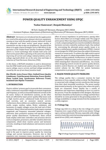
The voltage quality that a consumer receives for load operationorfromaspecificutilityiscritical.ThePQproblem isconcernedwithvoltage/currentwaveformsthatdeviate from their ideal sinusoidal waveforms. The power quality deterioratedprimarilyatthetypicalsiteswherethegrid's loads are connected. Power Quality has a variety of definitionsandimportancedependingonhowitisusedin theprocess.Fromthestandpointofthedesigner,PQmeans thatthereshouldbenofluctuationinvoltageandthatthere shouldbenonoisegeneratedinthegroundingsystem.It's voltageavailabilityoroutageminutesfromthestandpointof autilityengineer.
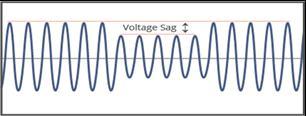
2.1 Voltage Sag
Voltagesagreferstoa drop inthermsvoltageofa power frequencyoveraspanofhalfacycletooneminute.Voltage sagisaseriousanddrasticPQissue,especiallywithvoltagesensitiveloadslikecontrolprocessingequipment,adjustable speeddrives(ASD),andcomputers.
Relays getting tripped, loads malfunctioning, damage or completefailureoftheequipmentfoundintheloadendare justafewofthedrasticeffectsobservedasaresultofvoltage sagdifficulties.
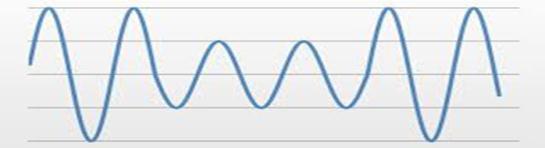
2.2 Voltage Swell
Voltageswellisasuddenincreaseinthermssupplyvoltage varying in a range from 1.1p.u. to 1.7 p.u., with a approximatetimerangeoffromhalfacycleto1min.These appearduetolargeloadssuddenshutdown,capacitorbanks gettingenergized,orduetofewfaultsproducedinsidethe power system. Its occurrence probability appear when compared to voltage sags is very much less, but these are moreharmfultosensitiveequipment/non-linearloads
2.3 Interruption
Interruptionisdegradationincurrentorlinevoltageupto 0.1puofthenominalvalue.Itisonlyforadurationof60 seconds and does not extend beyond that. Equipment failures, power system faults, and control errors are the sourcesofinterruption.
2.4 Waveform Distortion
A power system network tries to generate a sinusoidal voltageandcurrentwaveform,butitisunabletodosodue toaproblem,anddistortionsdevelopasaresult.
Therearemanycausesofwaveformdistortion:
(i) DC Offset: In an AC power system, a DC offset is the existence of DC voltage or current. The signal drifts fromitsrealreferencelocationduetoDCoffset.
(ii) Notching: When power electronics equipment is commutated,voltagedisturbancesarecreatedregularly duetocurrenttransferfromonephasetoanother
(iii) Harmonics: Harmonic currents and voltages are sinusoidalcurrentsandvoltagesthatoperateatinteger multiples of the fundamental frequency. Non-linear loadsarethesourceofharmonics
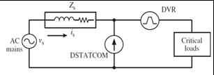
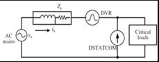
3. CLASSIFICATION OF UPQCS
UPQCs can also be classified based on the topology used, suchasrightshuntUPQCsandleftshuntUPQCs.
4.1 Design of the system
Theideausedhereistoproduceharmoniccurrenthaving componentswhichhas180°phaseshifttothecomponents of harmonic current which are generated by the use of nonlinear loads. The concept here, is totally based on injecting harmonic current in the ac system similar in amplitudebutoppositeinphasewhencomparedwithload currentwaveformharmonics.
In normal conditions, the source is assumed as a perfect sinusoidalvoltagei.e
Vs=VmSin(ωt)
Nowafterapplyinganon-linearloadandasdiscussedabove, theloadcurrentwillhavebothfundamentalcomponentand alsoharmonicsofhigherorder.Thiscurrentwerepresent as:
(t)= sin(nωt + )
Now,theloadpowerisexpressedas:-
(t) = (t) (t) = (ωt) cos + sin(ωt) cos(ωt)sin + sin(ωt) sin(nωt+ )
=��s(t)+��c(t)
Inaboveeqn.wedefine��s(t)asrealpowergivenbyutility source, and �� c(t)as the reactive power and the harmonic power.
FromabovediscussionweknowthatAPFwillprovidethe reactiveandharmonicpower����(��),thecurrentsuppliedby sourceisgivenas:-
(t)= = cos sin(ωt) = sin(ωt)
Thecurrent is(t)isandutilityvoltageisseentobeinphase andpuresinusoidal.Atthistime,theAPFwillprovidethe followingcompensationcurrent ic inthecircuit.
ic(t )= il(t) – is(t)
5. PQ THEORY & ANALYSIS
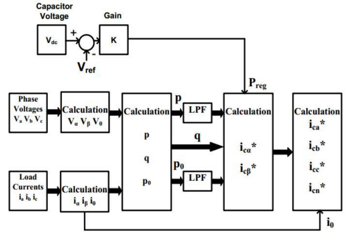
5.1 INSTANTANEOUS POWER THEORY
H.Akagidefinedatheorybasedoninstantaneouspowerin threephasesystems,eitherwithorwithoutaneutralwire This p-q technique works in all situations, including transientandsteady-stateoperations.Thistheoryemploys variouswell-knowntransformationmodels,suchasClarke's Transformation. The voltage and current waveforms are measured here, and then transformed from a-b-c coordinates to zero coordinates. Following this transformation,wecalculateactiveandreactivepowerusing a series of equations, and then remove the power components with harmonics by passing them through a suitablelowpassfilterwithasuitablefrequency.Weidentify thereferencesourcecurrentinthisframeonlyandthenuse Inverse Clarkes Transformation to convert this reference sourcecurrentbacktoa-b-ccoordinatesusingthisnewset of power and already derived new voltages in a different coordinate, namely zero coordinates. This new reference sourcecurrentisthencomparedtoactualobservedsource currentwaveforms,withtheerrorbeingfedviaahysteresis controller with a specific band to obtain a different gate pulseforinverteroperation.Thefollowingisabasicblock diagramthatexplainstheentireoperationofthissignificant p-qtheory:-
controlstrategytogeneratereferencecurrent
5.2 Analysis of P-Q Approach
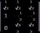
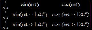
Clarke’s transformation needed for converting source voltage and current from a-b-c to �� − �� – 0 coordinate is givenbyfollowingmatrix:-
Similarlycurrenttransformationis:-
Here we define ��r(��)=
αs(t)+��βs(t) as instantaneous real power& �0s(t)asinst.Powerofzerosequence.Herewecan note down an important benefit of this transformation in which separation of system zero sequence component is easilydone.
5.3 Compensation Strategy
Inordertocompensate Pαq & Pβq bywhich Pαq + Pβq = 0,the filterisinjectingcompensatingcurrentnamely iαc & iβc to reactivecurrentsuchthat:-
Thecurrent iαc isprovidingthepower Pαq and iβc isproviding thecomponent Pβq .Sothevoltage������ &������ needtoprovide only Pα�� and Pβ�� It can also be noted that, the power necessarytocompensatefor iαq isequaltothenegativeof thepowernecessarytocompensatefor iβq
Thecurrentsources iαc and iβc isrepresentingAPF,whichis generated from the VSI inverter & they are controlled accordinglytoproduce iαq and iβq.HencenosourceofDCis necessaryandnolargeenergystorageelementisessential forcompensatingthereactivepowers.Thereactivepower required by one phase is instantaneously supplied by the other phase. Hence size of capacitor is not depend on the amountofreactivepowerwhichneedstobecompensated.
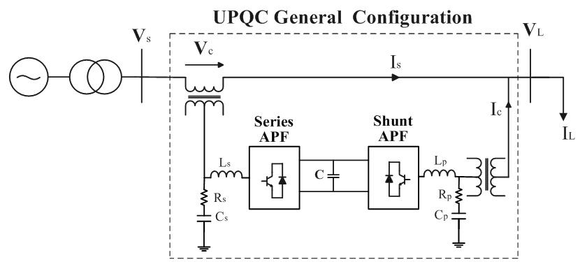
6. SYNCHRONOUS REFERENCE FRAME CONTROL OF UPQC
For the operation of the UPQC model, the SRF controlling approach is quite similar to the instantaneous reactive power theory method. The fact that only load current is required for the creation of reference current is a key characteristic of this algorithm, which means that disturbancesinthesourceorvoltagedistortionswillhaveno detrimental impact on the performance of the intended UPQC system. We optimised the system without using transformervoltage,load,orfiltercurrentmeasurementsin the suggested SRF approach for UPQC. As a result, the number of measurements is reduced, and system performanceisimproved.
Signals of current and voltage are first sensed and then translatedintoa rotatingframe(dq0)inthismethod.The transformationangle(ωt)denotesthesuggestedreference frame'sangularposition.Thisiscoordinatedwiththe3-ac voltageandrotatesataconsistentspeed.PLLmethodsfind loadreactivecurrentsandharmoniccurrentsundertheset condition of a nonlinear load. Then, to compensate for neutral current, harmonics, and reactive power, currents withthesameamplitude but reversephasearegenerated and injected into the proposed system. The α−β−0 coordinatesarestationaryinthestationaryreferenceframe, whereasthed-q-0coordinaterotatesinsynchronismwith supplyvoltagesintheSRF.
6.1 ���� & ���� Components Definition
Accordingtothesuggested SRFtheory,the“d”coordinate componentofcurrent,i.e.,thepositive-sequencecomponent, isalwaysinphasewithvoltage.Thecurrent's"q"coordinate component, iq, is discovered to be perpendicular to the current's "id" component. This iq is known as negative sequence reactive current. We call the "0" coordinate componentofcurrentthezerosequencecomponentsinceit isorthogonaltobothidandiq.
If iq is discovered to be negative, the load will pursue inductivereactivepower;ifitisfoundtobepositive,theload will pursue capacitive reactive power. In the proposed nonlinear power systems, the id and iq components will havebothoscillating(id&iq)andaveragecomponents(id& iq),asshownintheequationbelow,
Theoscillatingpartrespondstotheoscillatingcomponentin both coordinates, while the average part relates to active current(����)andreactivecurrent(����).Asaresult,wherever APFapplicationsareused,ourgoalwillbetoseparatethe fundamental positive sequence component in order to reduceorremoveharmonics
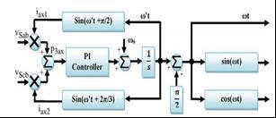
6.2 Modified Phase Locked Loop
ThetypicalPLLwillfunctionpoorlyforlargedistortionand unbalancedsystems,andthetransformationangle(ωt)will not vary completely linearly with time as required. Under highlydistortedconditions,amodifiedPLLcanbeutilisedto improve the quality of the UPQC filtering operation and results.
Fig -7 PLLblockdiagram
Firstwecalculatethe3-∅instantaneoussourcelinevoltages & ��������. This measured line voltages is multiplied with auxiliary(������1&������2)feedbackcurrentsofunityamplitude, inwhichonewillleadleads120°fromtheothertoachieve auxiliaryinstantaneousactivepower( ).Thisispassed throughaP-Icontroller.Thereferredfundamentalangular frequency( =2πf)isaddedtoresultofP-Icontrollerfor the purpose to stabilize output. The result is then passed throughanintegratorblocktogetauxiliarytransformation angle(ωt).Theresultantproducedωtleads90°tosystem’s fundamental frequency; and hence −90° is added to integratoroutputforgettingsystemfundamentalfrequency.
Whenthisinstantaneouspower reacheszeroorgetslow frequency oscillation then PLL is said to reach a stable operatingpoint.Alsotheoutputωtwillreachfundamental positivesequencecomponentoflinevoltage.
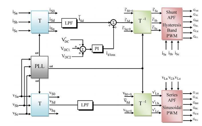
6.3 Reference-Voltage Signal Generation for series
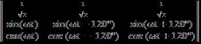
In the UPQC model, the control algorithm for series APF entails calculating the reference voltage that must be injected by the series transformer, which it does by comparing the component of positive sequence of source voltage with the load voltages. The source voltage is measured and then translated into the d-q-0 frame of referenceusingthematrixbelow:
��� & ������ are the instantaneous components in the new SRFandbothofthemhasgotoscillating(Vsd&Vsq)aswellas averagecomponents(Vsd&Vsq inthem.Theoscillatingpart includeswithinitharmonicandnegativesequentpartofthe utilityvoltageduetonon-linearload.Theaverageparthas withinitthepositivesequencevoltagecomponent.
Hencewecansaythat:-
Vsd =Vsd Vsq
Theharmonicpartisseparatedbypassingthed-component voltage V_sdvia LPF. The output of this LPF is only the averagecomponentV sd.Thezeroandnegativecomponents namely������&����0ofsourcevoltageisterminatedormadeto zero for compensating harmonics of load voltage, and unbalance. The reference load voltage is calculated by passing the new set of components of d-q-0 frame via a inverse transformation which converts it again to the originala-b-creferenceframe.Thisinversetransformation calledInverseParkstransformationisshownbelow:-
=
Theresultantreferencevoltagesasabove(��* ����,��* ����,&��* ����) andactualsensedloadvoltages(������,������&������)arecompared and then passed via a sinusoidal pulse width modulation(PWM)forcontrollingswitchingorgatesignals for the series filter operation of IGBT used and to fight against and remove all problems related with voltage, harmonics in voltage, sag/swell, voltage unbalance at the PCC.Thewholeideaofgeneratingreference
Fig-8 SRFcontrolforUPQCoperation
6.4Reference-Source-Current SignalGenerationfor Shunt APF
TheshuntAPFasdiscussedearlierisusefulforavoidingthe problemsrelatedwiththecurrentharmonicsgeneratedin ourUPQCmodelwithnonlinearload.Italsotakescarefor reactivepowercompensation.Thesensedsourcecurrentare transformed to d−q−0 coordinates by the same Parks transformationequation,wheretheangularfrequency(ωt) comesfrommodifiedPLL.
= T
T=Parkstransformationmatrix
Thenewtransformedinstantaneoussourcecurrentind-q-0 framenamely������&������againincludesinitbothoscillating components(������ &��)andaveragecomponents(������ ������)as well. Oscillating component will contain a combination of harmonicsandnegativesequencecomponentwhereasthe averagecomponentincludesonlypositivesequencecurrent componentwhichcorrespondstoreactivecurrent.Thezero sequence part (����0) will appear under unbalanced load conditions. In our SRF method average component of positive-sequence (������) in the d-axis and the zero- and negative-sequence component(����0& ������)inthe0- and qaxesofthesourcecurrents,inforcompensatingharmonics andunbalancesproducedinthenon-linearload.
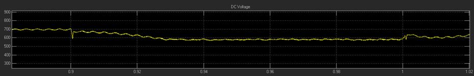
For compensating the active power losses of the UPQC powercircuit,SeriesAPFinjectsactivepowerinthepower system,whichresultsinregulationofdc-linkvoltageacross capacitor.Tomakedc-linkvoltageconstant,apartofactive poweristakenfromthepowersystembyshuntAPF.Forthis task,thevoltageofdc-linkiscomparedwithasetreference value(������),andthenpassedthroughaPIcontrollerwhose output is the required active current (������������). The dcomponentofsourcecurrenti.e������ispassedthroughaLPF
to get its average component i.e (������) .Now this average componentandrequiredactivecurrenti.e������������areadded togetfundamentalreferencecomponent. ��’����= isd + ������������
The zero sequence and negative sequence component of source current is set to zero to compensate, distortion, harmonics, and reactive power in source current. The reference source current is produced by inverse Parks transformationasmentionbelow:-
Where, T-1 = inverse Parks transformation Both the measuredandreferencesourcecurrentarecomparednow andpassedthroughhysteresisbandcurrentcontrollerfor gettingthegatingsignalsforoperationofshuntAPFinthe givenUPQCmodelandtherebyeliminatingallthecurrent relatedproblemfromthesystem
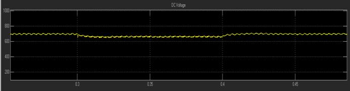
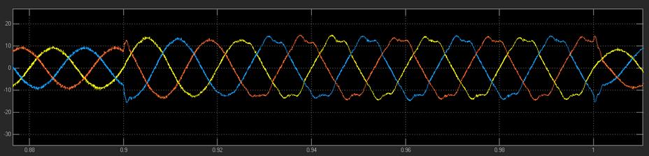
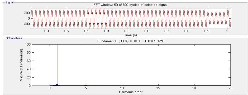
7. RESULTS
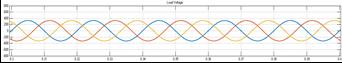
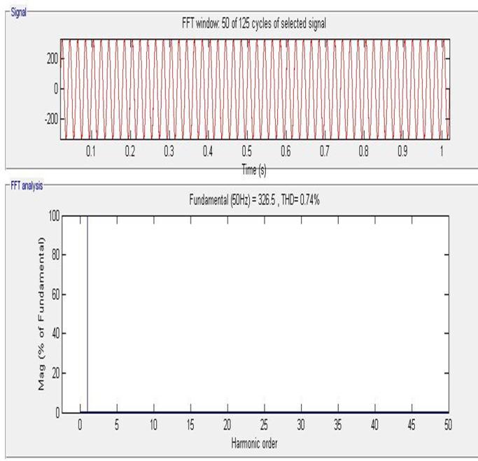
7.4 FFT analysis of Load voltage With UPQC
8. CONCLUSION
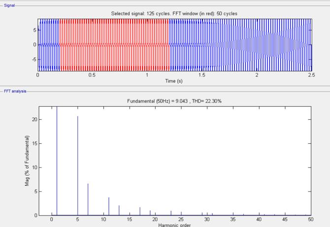
This work outlines an improved control method for the UPQC system's operation. For the APF operation, several control techniques are investigated, including p-q theory, SRF-basedtechnique,andunitvectortemplatecreation.The SRFtheoryisusedtosimulatetheUPQCmodelinMATLAB. The UPQC system's shunt portion eliminates all currentrelated harmonic problems, while the system's seriesconnectedAPFeliminatesallvoltageharmonicscausedby theuseofnonlinearloads.ThetotalTHDinthesystemhas improved,asseenbythewaveformsdisplayingtheresultant THDbeforeandafterUPQCoperation.
REFERENCES
[1] D. C. Bhonsle, R. B. Kelkar, “Design and Simulation of Single Phase Shunt Active Power Filter”, 2011 International Conference on Recent Advancements in Electrical,ElectronicsandControlEngineering.
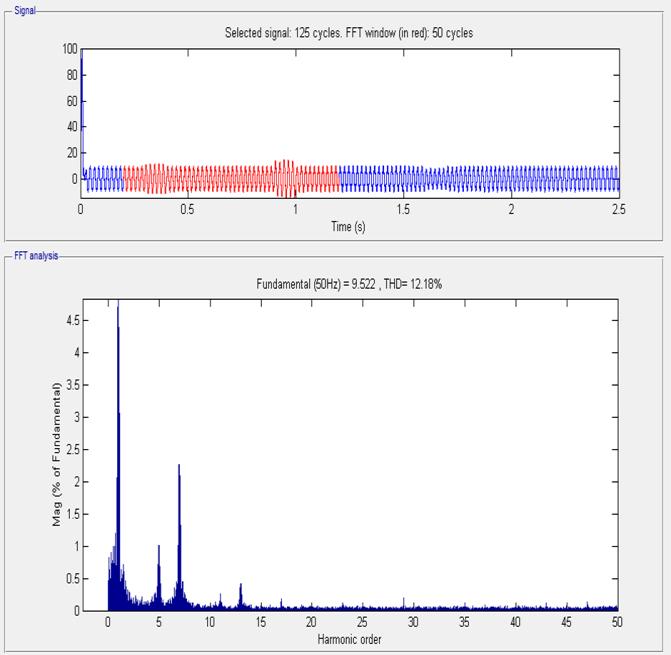
7.5 FFT analysis of source current
[2] V. Khadkikar, P. Aganval, A. Chandra, “ A Simple New Control Technique For Unified Power Quality Conditioner (UPQC)”, 2004 11th International ConferenceonHarmonicsandQualityofPower.
[3] Akagi,Y.Kanazawa,A.Nabae,“GeneralizedTheoryof the Instantaneous Reactive Power in Three Phase Circuits”, in Proc. IPEC-Tokyo’83 Int. Conf. Power Electronics,Tokyo,pp.1375-1386
[4] M.Kesler,E.Ozdemir,Senior Member, “SynchronousReference-Frame-BasedControlMethodforUPQCunder unbalanced and distorted load conditions”, IEEE transactions on industrial electronics, vol. 58, no. 9, september2011.
7.6 FFT analysis of load current
[5] I.Axente,M.BasuandM.Conlon,“dclinkvoltagecontrol of UPQC for better dynamic performance”, Electric PowerSystemsResearch81(2011)1815–1824.
[6] Yash Pal, A. Swarup, Bhim Singh, “A control strategy based on UTT and Icosɸ theory of three phase , four wire UPQC for power quality improvement ” International Journal of Engineering, Science and TechnologyVol.3,No.1,2011,pp.30-40.
[7] S.Shankar, A.Kumar and W.Gao “Operation of Unified Power Quality Conditioner under Different Situation,” IEEEProc.PowerandEnergySocietyGeneralMeeting, July2011,pp.1-10.
[8] B.Singh,A.ChandraandK. A.Haddad,PowerQuality: Problems and Mitigation Techniques. London: Wiley, 2015.
[9] Design & performance analysis of 3-phase solar PV IntegratedUPQCSachinDevassy;BhimSingh,2016
[10]Metin Kesler and Engin Ozdemir, “A Novel Control MethodforUnifiedPowerQualityConditioner(UPQC)
Under Non-Ideal Mains Voltage and Unbalanced Load Conditions,” IEEE Conference on Applied Power Electronics,Feb.2010,pp.374-379
[11]MekriFatiha,MachmoumMohamed,Ait-AhmedNadia “New hysteresis control band of an unified power quality conditioner” M. Fatiha et al. /Electric Power SystemsResearch81(2011)1743
1753
[12]V.Khadkikar,“Enhancing electricpower qualityusing UPQC:acomprehensiveoverview,” IEEE Transactions on Power Electronics,vol.27,no.5,pp.2284–2297,2012.
[13]M. Kesler and E. Ozdemir, “Synchronous-referenceframe-based control method for UPQC under unbalanced and distorted load conditions,” IEEE Transactions on Industrial Electronics,vol.58,no.9,pp. 3967
3975,2011.
[14]N. Zhu, D. Xu, B. Wu, F. Liu, N. R. Zargari, and M. Kazerani, “Common-mode voltage reduction methods for current-source converters in medium-voltage drives,” IEEE Transactions on Power Electronics,vol.28, no.2,pp.995–1006,2013.
[15]P.E.Melin, J.R.Espinoza,L.A.Moran etal.,“Analysis, design and control of a unified power-quality conditionerbasedonacurrent-sourcetopology,” IEEE Transactions on Power Delivery,vol.27,no.4,pp.1727–1736,2012.
[16]A. Terciyanli, M. Ermis, and I. Cadirci, “A selective harmonic amplification method for reduction of kVA rating of current source converters in shunt active powerfilters,” IEEE Transactions on Power Delivery,vol. 26,no.1,pp.65–78,2011.
[17]V. Kinhal, P. Agarwal, and H. O. Gupta, “Performance investigation of neural-network-based unified powerquality conditioner,” IEEE Transactions on Power Delivery,vol.26,no.1,pp.431–437,2011.
[18]C.H.daSilva,R.R.Pereira,L.E.B.daSilva,G.LambertTorres,B.K.Bose,andS.U.Ahn,“AdigitalPLLscheme for three-phase system using modified synchronous reference frame,” IEEE Transactions on Industrial Electronics,vol.57,no.11,pp.3814–3821,2010.