Design and Analysis of Ignition based on RFID by Arduino Nano Compiler
Karibasavaraja D1 , Chirag2 , Deepak A3 , Dhanush G M4 , Praveen Kumar K5
1Assistant Professor, Department of I&P Engineering, JSSTU, SJCE, Mysore
2Undergraduate, Department of I&P Engineering, JSSTU, SJCE, Mysore

3Undergraduate, Department of I&P Engineering, JSSTU, SJCE, Mysore
4Undergraduate, Department of I&P Engineering, JSSTU, SJCE, Mysore
5Undergraduatex, Department of I&P Engineering, JSSTU, SJCE, Mysore ***
ABSTRACT - The ultimate goal of this paper is incorporating of keyless security system for two-Wheeler vehicle in order to have reliable, secured mechanism to safeguard two-wheeler vehicles from thieves. The other secondary objectives of this attempt are to develop keyless, user friendly, conventional locking system. As per our literature surveystudy, it’s clearlyindicating that nowa days a lot of two wheelers vehicle has been stolen, average 10 to 15 vehicles per day have been stolen reported in Mysore district alone. Therefore, there is scope to develop the highly anti-theft security system to secure the best guarantee to protect the two-wheeler vehicle from different kinds of theft cases. In this paper, two-wheeler vehicles have been chosen, due to readily available with us. The methodology of this paper is the first stage will be the understanding the present unsafe locking mechanism. The second stage will be understanding complete keyless concepts and compatibility with existing product without changing major systems. By implementing this keyless highly secured system in twowheeler vehicle it will protect the vehicles from thieves, gives 100% confident to user for safe guarding of their vehicles, easy handling, user friendly concept, saving natural resources by making of keys through this cost saving can be achieved. Easy handling and cost saving system. This system has many advantages over the present.
Key Words: Micro Controller, RFID Reader, Relay Drive, Regulated power source, Ignition system
1.INTRODUCTION
This paper is a fine combination of RFID technology and “Engine Ignition technology”. It makes use of RFID reader to detect RFID tags. RFID reader uses various types of techniques like object detection and modulating and demodulatingradiofrequency.
InthispaperwehaveusedRFIDtechnology.Mainblocks ofthispaperareMicrocontroller,RFIDreader,Relay,LED andRPS.UserhastoplaceauthorisedRFIDtagontheRFID reader.ThemainfeatureorspecialtyofRFIDTagisthatit is unique. It gives this paper the high-level security than other security systems, such as Password based security
system. As RFID card are ergonomically designed in such a waythatitcanbecarriedinawallet.AuthorizedRFIDtagis read by a special type of sensor. RFID Reader can be interfacedwithamicrocontroller.Throughsoftwarewe can addactivatenewRFIDtagsanddeactivatetheexisting user, also identify the user by selecting corresponding option throughthesoftware.
The main aim of this paper is to develop an authentication system on two-wheelers based on RFID thatcanbeusedtosecurethetwo-wheelerfromtheft.In this paperweuseaRFIDreadertoreadonceidentityto turn onignition system. For this, we use a microcontroller to enable the ignition system. If the matching between scanned data and the already existing data is correct, Ignition turns ON. This paper will utilize RFID reader as theinputtoacquiredigitaldataandtoignitetheengine.
2. Literature Survey (IGNITION BASED ON PASSWORD)
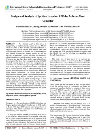
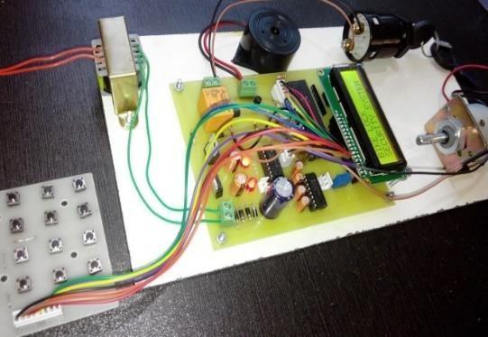
Many times, we hear the cases of bikes getting stolen from the parking area. Or sometimes we forgot to removethekeysfromthebikebymistake.Inthesecases, itis really difficulttogetthebikeback.“Passwordbased Lock for Bike security with ignition key” paper is designedtosolvethispurpose.Themainconceptbehind this paper is a bikesecurity system using a password entered through a keypad. This system turns on the Buzzerwhenthewrongpasswordisentered3times.
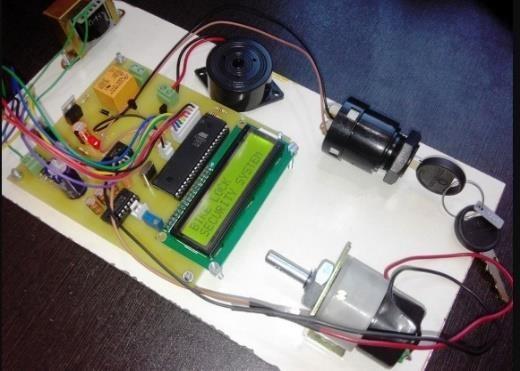
Whenever user inserts key in ignition lock, LCD displayshowsmessageas“EnterPassword:”.Userhasto enter password using Keypad provided with this electronicspaper.Iftheenteredpasswordiscorrectthen RelayandDCmotoristurnedon.
User can change this password anytime he/she wishes using a keypad. This changed password is stored in externalEEPROMmemoryIC.Thus,bikesecuritysystem paper can store the changed password even if there is powercut.
2.1 Description in detail:
Passwordlockforbikepapermainlyconsists
1.Microcontroller:ThisistheCPUofelectroniclockforbike paper.Heremicrocontrollerof8051familyisused.
Thevariousfunctionsofmicrocontrollerare
I.ReadingthedigitalinputfromKeypad
II. SendingthisdatatoLCD,sothatthepersonoperating thispapershouldreadthepassword
III. Sensing the password using keypad and to check whether it is a correct password or a wrong password androtatethemotorifthepasswordenteredisacorrect password.
2. LCD: Here 16×2 alphanumeric Liquid Crystal Display (LCD) is used, which means it can display alphabetsalongwithnumberson2lineseachcontaining 16characters.
3. Buzzer: Here buzzer is used to indicate the wrong passwordtoopentheignition.
4. Keypad: User will enter the password using the keypad.
Variouskeysofkeypadareasfollowing,
I.0to9
II.Enter.
II.Escape.
2.2 Pictures of “Electronic lock for bike:
2.3 Applications and Advantages:
1.PasswordbasedLockforBikesecuritywithignitionkey papercanbeusedinvariousbikes.
2. The password detector paper can be used to automate the ignition locking process, so the user need not to carry the ignition lock keys along with them, they can just remember the password and use it later to open the ignition.
3. PRESENT WORK
FromtheblockdiagramwiththehelpofRFIDreaderand theinputisprovidedtothemicrocontrollerandonthebasis oftheinputreceivedfromtheRFIDreader,microcontroller drivestheoutputdevicesi.e.,ignitionsystemofthebikeand theLED.ScanningandcheckingoftheRFIDtagisdonewith thehelpoftheRFIDreaderandonthebasisoftheoutputof the module microcontroller drive the ignition system of bike. Only authorized RFID tag is stored in the module. If matchconditionoccurignitionsystemofthebikeisturned on.
•Vehicle Battery Source: - The power is supplied to the Arduinothroughamicro-USBcable.
•RPS: - Used for constant voltage and regulation. The minimuminputvoltageisbetween6.8V–24V.
•Microcontroller:-Itisusedforserialcommunicationand executionoftheprogram.
•RFIDReader:-UsedtogatherinformationfromRFIDtag.
•Relay Drive: - Switching the Relay forCurrent Amplification.
•Relay:-UsedforHighvoltageandLowvoltageIsolation.
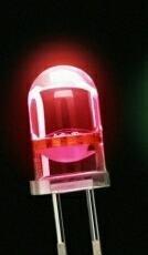
•LED:-LEDisused,thered-lightglows whentheinputis matchedwiththestoreddataandallowsignitiontoturnon.
3.1 METHODOLOGY
Fig:Blockdiagramprototype
From the block diagram with the help of RFID reader and the input is provided to the microcontroller and on the basis of the input received from the RFID reader, microcontroller drives the output devices i.e., ignition system of the bike and the LED. Scanning and checking of the RFID tag is done with the help of the RFID reader and on the basis of the output of the module microcontroller drive the ignition system of bike. Only authorized RFID tag is stored in the module. If match condition occur ignitionsystemofthebikeisturnedon.
Vehicle Battery Source:- The power is supplied to the ArduinothroughamicroUSBcable.
RPS: - Used for constant voltage and regulation. The minimuminputvoltageisbetween6.8V–24V.
Microcontroller: - Itisusedforserialcommunicationand executionoftheprogram.
RFID Reader: - UsedtogatherinformationfromRFIDtag.
Relay Drive: - Switching the Relay for Current Amplification.
Relay: - UsedforHighvoltageandLowvoltageIsolation.
LED: - LED is used, the red-light glows when the input is matchedwiththestoreddataandallowsignitiontoturn on.
3.2 TECHNICAL SPECIFICATION
SoftwareComponents
1.Programminglanguage(Embedded-C).
2.ArduinonanoCompiler.
Programming language (Embedded System)
An embedded system is an application that contains at leastoneprogrammablecomputer(typicallyintheformof a microcontroller, a microprocessor or digital signal processorchip)andwhichisusedbyindividualswhoare, in the main, unaware that the system is computer-based. This type of embedded system is all around us. Use of embedded processors in passenger cars, mobile phones, medical equipment, aerospace systems and defence systems are widespread, and even everyday domestic appliances such as dishwashers, televisions, washing machines and video recorders now include at least one such device.
Arduino Software
The Arduino programming language is a simplified versionofC/C++.IfyouknowC,programmingtheArduino willbefamiliar.IfyoudonotknowC,noneedtoworryas only a few commands are needed to perform useful functions.AnimportantfeatureoftheArduinoisthatyou cancreateacontrolprogramonthehostPC,downloaditto theArduinoanditwillrunautomatically.RemovetheUSB cable connection to the PC, and the program will still run fromthetopeachtimeyoupushtheresetbutton.Remove the battery and put the Arduino board in a closet for six months.Whenyoureconnectthebattery,thelastprogram
you stored will run. This means that you connect the boardto the host PC to develop and debug your program, butoncethatisdone,younolongerneedthePCtorunthe program.
Hardware Components
International Research Journal of Engineering and Technology (IRJET) e-ISSN:2395-0056
Volume: 10 Issue: 01 | Jan 2023
1. RegulatedPowerSupply
www.irjet.net
A Regulated Power Supply is an embedded circuit; it covertsunregulatedACintoconstantDC.
Withthehelpofarectifier,itconvertsACSupplyintoDC. Its function is to supply a stable voltage (or less often current), to a circuit or a device that must be operated within certain power supply limits. The output from the regulated power supply may be alternating or unidirectional, but is nearly always DC. The type of stabilizationusedmayberestricted to ensuringthat the output remains within certain limits under various load conditions, or it may also include compensation for variations in its own supply source. The latter is much morecommontoday.
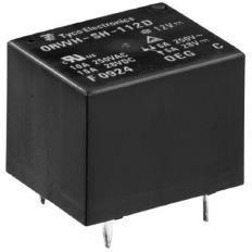
A Relay is an electrically operated switch. Current flowing through the coil of the relay creates a magnetic field which attracts a lever and changes the switch contacts.
p-ISSN:2395-0072
which can be completely separate from the first. For example, a low voltage battery circuit can use a relay to switch a 230V AC mains circuit. There is no electrical connection inside the relay between the two circuits; the linkismagneticandmechanical. Thecoilofarelaypasses a relatively large current, typically 30mA for a 12V relay, but it can be as much as 100mA for relays designed to operate from lower voltages. Most ICs (chips) cannot provide this current and a transistor is usually used to amplifythesmallICcurrenttothelargervaluerequiredfor therelaycoil.Themaximumoutputcurrentforthepopular 555 timer IC is 200mA so these devices can supply relay coilsdirectlywithoutamplification.
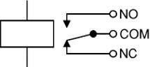
The coil current can be on or off, so relays have two switch positions and they are double throw (changeover)switches.Relaysallowonecircuittoswitch asecondcircuit
Therelay’sswitchconnectionsareusuallylabelledCOM, NC and NO: COM = Common, always connect to this; it is themovingpartoftheswitch.NC=NormallyClosed,COM isconnectedtothis whentherelaycoilisoff. NO=Normally Open,COMisconnectedtothiswhentherelaycoilison.
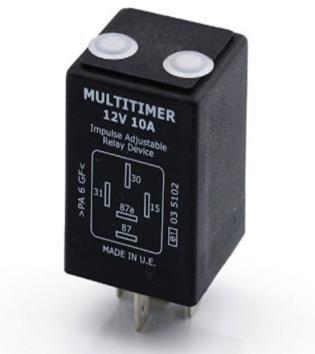
Relay driver circuit, is a circuit which can drive, or operate, a relay so that it can function appropriately in a circuit.Thedrivenrelaycanthenoperateasaswitchinthe circuit which can open or close, according to the needs of thecircuitanditsoperation.
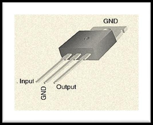 Fig:RPS
2. Relay
Fig:Relay
3. RelayDrive
Fig: RelayDrive
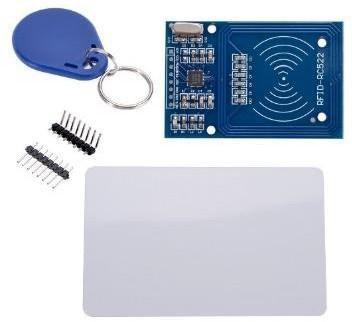
4. RFID
Fig:RFIDreaderandtag
Fig:RPS
2. Relay
Fig:Relay
3. RelayDrive
Fig: RelayDrive
4. RFID
Fig:RFIDreaderandtag
Volume: 10 Issue: 01 | Jan 2023 www.irjet.net
Radio-frequencyidentification(RFID)useselectromagnetic fields to automaticallyidentify and track tags attached to objects. An RFID system consists of a tiny radio transponder, a radio receiver and transmitter. When triggeredbyanelectromagneticinterrogationpulsefroma nearby RFID reader device, the tag transmits digital data, usually an identifying inventory number, back to the reader.Thisnumbercanbeusedtotrackinventorygoods. Passive tags are powered by energy from the RFID reader's interrogating radio waves. Active tags are powered by a battery and thus can be read at a greater rangefromtheRFIDreader,uptohundredsofmeters.
Unlikeabarcode,thetagdoesnotneedtobewithinthe
line of sight of the reader, so it may be embedded in the tracked object. RFID is one method of automatic identificationanddatacapture(AIDC).
The Arduino microcontroller is an easy to use yet
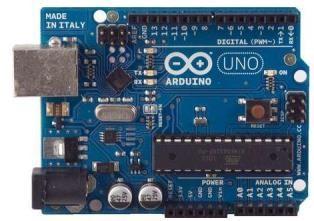
powerful single board computer that has gained considerable traction in the hobby and professional market. The Arduino is open-source, which means hardware is reasonably priced and development software isfree.
ThisiswhatArduinoBoardlookslike.
The Arduino board features an Atmel ATmega328 microcontrolleroperating at 5V with2 Kb ofRAM,32 K of flashmemory forstoringprograms and1 Kb ofEEPROM for storing parameters. The clock speed is 16 MHz, which translates to about executing about 300,000 lines of C source code per second. The board has 14 digital I/O pins and 6 analog input pins. There is a USB connector for talking to the host computer and a DC power jack for connecting anexternal 6-20 Vpower source, forexample a 9 V battery, when running a program while not connectedto the hostcomputer. Headersare provided for interfacing to the I/O pins using 22 g solid wire or header connectors.
6. LED
p-ISSN:2395-0072
ALight-emittingdiode(LED) is atwo-leadsemiconductor lightsource.
LED
TheswitchingONofthe deviceisindicatedwhen LED(Red)glows.
Needs for Working System
1.ArduinoDuemilanoveboard.
2.USBprogrammingcable(AtoB.)
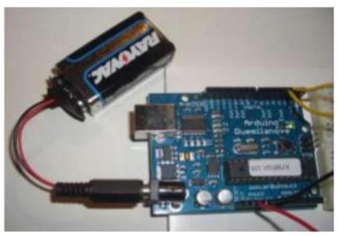
3. 9V battery or external power supply (for stand-alone operation.)
4. Solder less breadboard for external circuits, and 22 g solidwireforconnections.
5.HostPCrunningtheArduinodevelopmentenvironment.
Versions exist for Windows, Mac and Linux 1.3 Installing the Software Follow the instructions on the Getting Startedsection of the Arduino web site, Go all the way through the steps to where you see the pin 13 LED blinking. This is the indication that you have all software and driverssuccessfully installed and can start exploring with your own programs. 1.4 Connecting a Battery For stand-aloneoperation, the board is powered by a battery rather than through the USB connection to thecomputer.
While the external powercanbeanywhereinthe range of 6 to 24 V (for example, you could use a car battery), a standard9Vbatteryisconvenient.Whileyoucouldjamthe leadsofabatterysnapintotheVinandGndconnectionson theboard,itisbettertosolder thebatterysnapleadstoa DCpowerplugandconnecttothepowerjackontheboard. DisconnectyourArduinofromthecomputer.Connecta9V battery to the Arduino power jack using the battery snap adapter. Confirm that the blinking program runs. This showsthatyoucanpowertheArduinofromabatteryand that the program you download runs without needing a connectiontothehostPC.
Fig:WorkingsystemofArduino
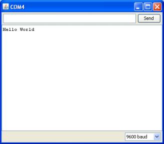
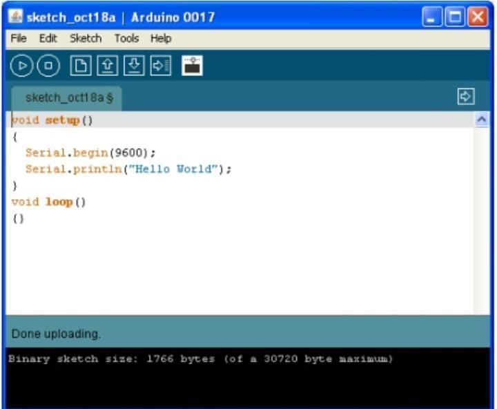
Connect your Arduino to the computer with the USB cable. You do not need the battery for now. The green PWR LED will light. If there was already a program burned into the Arduino, it will run. Start the Arduino development environment. In Arduino-speak, programs are called “sketches”, but here we will just call them programs.
In the editing window that comes up, enter the following program, paying attention to where semicolonsappearattheendofcommandlines.

Click the Upload button or Ctrl-U tocompile the program and load on the Arduino board. Click the Serial Monitor button.Ifallhasgonewell,themonitorwindowwillshow yourmessageandlooksomethinglikethis.
Click the Upload button or Ctrl-U to compile the program and load on the Arduino board. Click the Serial Monitor button. If all has gone well, the monitor window willshowyourmessageandlooksomethinglikethis.
PushtheArduinoresetbuttona fewtimesandsee what happens.
Ifthereisasyntaxerrorintheprogramcausedbyamistake intyping, an error messagewill appear inthe bottom of theprogram window. Generally, staring at the error will revealtheproblem.
If you continue to have problems, try these ideas Run
theArduinoprogramagain
•CheckthattheUSBcableissecureatbothends.
• Reboot your PC because sometimes the serial port can lockup
• If a “Serial port…already in use” error appears when uploading
4. RESULTS AND DISCUSSIONS
•RFID technology automates data collection and vastly reduceshumaneffortanderror.
•There is no need to remember the password or any Pin number.
•Oneofthemainadvantagesisthatthissystemremembers thestoreddata,evenifthepowersupplyisturnedoff.
•Itisacompactcircuitwhichmakesitveryeasytoinstallin thetwo-wheeler.
•Itcanbeusedinmopedaswellasingearbikes.
•Userfriendly.
Volume: 10 Issue: 01 | Jan 2023
•Spacingtobedone,inrequiredpartofthevehicle.
•CorrosionoftheRFIDreaderduetoweatherconditions.
•RFIDtagscanbestolen.
•RFID technology gains time more than other security systemsuchaspasswordandkey.
SampleparagraphDefineabbreviationsandacronymsthe first time they are used in the text, even after they have been defined in the abstract. Abbreviations such as IEEE, SI,MKS,CGS,sc,dc,andrmsdonothavetobedefined.Do not use abbreviations in the title or heads unless they are unavoidable.
In future this paper can be expanding further with fingerprintrecognitionalso.InthispaperwecanaddGPSto trace the vehicle’s exact location. Data can be sent to a remotelocationusingmobileorinternet.
•Otherrelatedmoduleslikefiresensor,GSMmodemcanbe implemented.

•Itcanbepermanentlyinstallednexttothehandlebarinthe two-wheeler,withanenvironmentfriendlybodydesign.
•In the future, smartphone can be interfaced by using BluetoothorWi-Ficonnectivity.
•Thiscanbefurtherimplementedinfour-wheelersaswell.
Limitations
• Spacingtobedone,inrequiredpartofthevehicle.
•CorrosionoftheRFIDreaderduetoweatherconditions.
•RFIDtagscanbestolen.
• RFID technology gains time more than other security systemsuchaspasswordandkey.
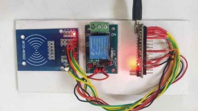
The Prototype of the model is as shown below
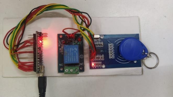
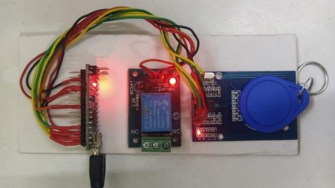
Working Prototype of the model
•Step1:-RFIDtagisplacedontheRFIDreader.
• Step 2: - If Input is matched, red light glows and ignitionstarts.
•Step 3: - If the input is not matched, when step 1 is carriedout.TheLEDwillnotglow,whichindicatesusing unauthorizedRFIDtag.
Theresultisthatthebikewillbeignitedonlywhenthe authorizedRFIDisscannedontheRFIDreader.Thedigital data of the authorized tags is stored in the RFID reader. WhenanypersonplacesauthorizedtagontheRFIDreader, thenthedata oftheplacedtagismatchedwiththe stored datainthemodule.IftheRFIDdataisfoundinthemodule, thenmatchconditionoccursandthemicrocontrollerignites thebikeotherwisebikewillnotstart.
Volume: 10 Issue: 01 | Jan 2023
5. CONCLUSIONS
TheprototypeofaRFID-basedignitionsystemdeveloped hasaspecificsequencethatmustbefollowedbeforeitcan beused toignitea vehicle. Basically,theRFIDrecognition softwaremustbefirstinitializedbeforefrequencydatacan beloadedfromafileofsamplefrequency.Thelastacquired RFIDisthenanalyzedanditsminutiaeidentified,extracted and stored as a template. The next step involves either enrollingthetemplateormatchingthetemplatewithother templates. The enrolment process button saves the last extractedtemplateintothedatabase.Theidentity number oftheenrolledtemplateisdisplayedinthelogwindow.The identificationprocesscomparesthequerytemplateagainst reference templates in a database. For verification, the identity number of the reference template to be matched withthequerytemplatemustbesupplied.Intheresults,it canbededucedthattheuseofRFIDsecuritysystemsoffers a much better and fool proof means of restricting the ignitionofvehiclesbyunauthorizedusers.Furthermore,it can be logically derived from the findings of this research workthat RFIDsignal can be usedfor motor vehicleignition systemcontrol.ParallelportcontrolcodesusedwithRFID analysis codes can provide capabilities for allowing only authorizedusers,authenticatedthroughtheirRFIDtagsto igniteavehicle.
Now-a-days thefts and accidents are increasing. To prevent from these problems this paper is implemented. ThetheftiscontrolledbytheRFIDmatchingprocess.
REFERENCES
[1] “Radio frequency identification” https://www.fda.gov/radiation-emittingproducts/electromagnetic-compatibility-emc/radiofrequency-identification-rfid
[2]https://www.techopedia.com/definition/26992/radiofrequency-identification-reader-rfid-reader
[3]https://www.atlasrfidstore.com/rfid-beginners-guide/
[4] Visa M. Ibrahim “Microcontroller Based Anti-theft SecuritySystemUsingGSMNetworkswithTextMessageas Feedback” Published in International Journal of Engineering Research and Development e-ISSN: 2278067X, p-ISSN:2278-800X, www.ijerd.com Volume2,Issue 10(August2012),PP.18-22
[5] Lin Hong. "Automatic Personal Identification Using Fingerprints",Ph.D.Thesis,1998.
[6] Yang S. and Verbauwhede I. (2003) “A Secure RFID Matching Technique”, http://www.emsec.ee.ucla.edu./pdf/2003acm.pdf
[7] http://auto.howstuffworks.com/ignitionsystem.htm, “HowAutomobileIgnitionSystemsWork“
[8]
http://www.RFIDinfo.org/.htm,“RFID Information Resource” [9] http://www.crimtrac.gov.au/RFIDanalysis.htm, “RFID Analysis–TheBasics” [10]R.K.Singh,“CrimeinIndia2011 -Statistics”,forNationalCrimeRecordsBureau2011[11] http//www.gogle/Ebedtronics.
[9] AlphaSigmaura Team (2005) “Computer Interfacing and control”, Paper presented at the workshop on Computer Interfacing and Control, LadokeAkintola UniversityofTechnology,Ogbomoso,Nigeria.
[10] Anton S. (2002) “Sorting it out: Machine learning and fingerprints”, Paper presented at the seminar on Telematik fingerprint, Siemens Corporate Technology, Munich,Germany.
[11] Engdahl T. (2005) “Parallel port interfacing made easy”,http://www.epanorama.net
[12] Graevenitz G.A. (2003) “Introduction to RFID technology”,A&SInternational,Vol.53,pp.84–86.
[13] http://auto.howstuffworks.com/ignitionsystem.htm, “HowAutomobileIgnitionSystemsWork“
[14] http://www.biometricinfo.org/fingerprintrecognition .htm,“RFIDInformationResource”
BIOGRAPHIES
Karibasavaraja D, Assistant Professor, Department of I&P Engineering,JSSTU,SJCE,Mysore

Chirag , Undergraduate , Department of I&P Engineering, JSSTU,SJCE,Mysore

Deepak A, Undergraduate , Department of I&P Engineering, JSSTU,SJCE,Mysore
Dhanush G M, Undergraduate , Department of I&P Engineering, JSSTU,SJCE,Mysore


Praveen Kumar K, Undergraduate , Department of I&P Engineering, JSSTU,SJCE,Mysore