POWER CONSUMPTION DETECTING AND ALERTING SYSTEM
S.V.Lakshmi1,R.Kalaiarasi2 , G.Sabarishwaran3 , M.Ganesh4 , D.Anantha Kumar 5 Ug Students , Department of Electronics and Communication 2 SNS College of TechnologyABSTRACT:-The main objective of this paper is to facilitate the consumers to efficiently use the power source from the power grid in order to maintain low electricity bill. This project will continuously monitors the power consumption by the home appliances and calculates its unit power consumption inorder to alert the consumer. Also when the user is very close to crosss the current slab rate it will send message to the user and alert the user to reduce the power consumption. This project also has auxilary load line design in which we can connect the non mandatory loads and once the power consumption is about to cross the current slab rate, the auxilary line is automatically cutoff and the status is updated to the consumer by message.
Keywords: slab rate,power,alert,loads,cutoff.
1. Introduction
Technologyhaschangedthewayhumansinteractwiththe physicalworldallacrosstheworldtoday.Electricityisone of the most brilliant creations in human history. Everythingweseeispoweredbyelectricityinsomeshape oranother.Many peopleareunfamiliar with the notion of electricity.Forsuchfolks,electricityisassimpleasturning ontheswitch,waitingforthedevicetostartworking,and then turning off the switch. When the power goes off, the significance becomes clear. The movement of electrical power or charge is referred to as electricity. Electricity is both a fundamental component of nature and one of the most extensively used types of energy We utilise electricityasa secondaryenergysourcesinceitiscreated byconvertingprimaryenergysourcessuchascoal,natural gas, nuclear energy, solar energy, and wind energy into electrical power. Electricity rates have recently risen due to a scarcity of energy. Price changes mainly reflect fluctuations in energy demand, generation source availability, fuel costs, and power plant availability. Summer prices are often the higher because more expensivegenerationsourcesareintroducedtomatch the increasingdemand.Asaresult,ordinarypeopleareforced to pay exorbitant prices for power As a result, we must monitortheirdailyenergyuseinordertoconserveenergy and money. Reducing energy use in our homes saves money,increasesenergysecurity,anddecreasespollution. Thesystem is tofacilitatetheconsumersto efficiently use thepowersourcefromthepowergridinordertomaintain
***
low electricity bill. This paper will continuously monitors the power consumption by the home appliances and calculates its unit power consumption inorder to alert the consumer when they are about to cross the current slab rate.Alsowhentheuserisveryclosetocrosssthecurrent slabrateitwillmakeaphonecallanssendsmstouserand alert the user to reduce the power consumption. This project also has auxilary load line design in which we can connect the non mandatory loads and Once the power consumption is about to cross the current slab rate, the auxilary line is automatically cutoff and the status is updatedtotheconsumerbymessage.
2. EXISTING TECHNIQUE:-
This existing technique proposes a system which eliminates manpower by self-regulating meter readings andbillgenerationreducingtheflawswhichareoneofthe major cause for energy-related corruption. Because there is no verification mechanism, there is a desire for transparency in the field of energy estimation. The Arduino Mega 2560 serves as the system's central controlling device. A microcontroller is used to link the ZMPT101B voltage sensor and the ACS712 current sensor for the energy metre. The voltage, current, power consumption, number of units, and associated pricing are computedandshownonthe16*2LCDDisplaymodule.As a fire safety precaution, an infrared-based flame sensor is employed. Monitoring of household appliances is accomplished through the use of 8-channel relay module to which loads are linked and controlled using voice commands via Google Assistant with the IFTTT platform, which is interfaced with the IoT-based Blynk app on mobile. The temperature and humidity within the home are monitored using a DHT11 sensor. All sensor readings are transferred to the Thingspeak cloud storage through theESP8266Wi-Fimodule.
3. SYSTEM HARDWARE:-
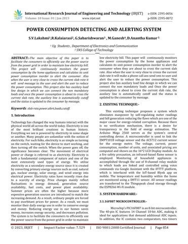
3.1.16F887 MICROCONTROLLER:-
Microchip'sPIC16F887isan8-bitmicrocontroller. The 40-pin IC features 14 Channel 10-bit ADC, making it ideal for applications that demand additional ADC inputs. In addition, the IC contains two comparators, two timers

(8-bit and 16-bit), and it supports the SPI, I2C, and UART communication protocols. The IC also has safety features such as Power-on Reset (POR), Brown-out Reset (BOR), Low Current Watchdog Timer (WDT), and others, making it appropriate for mission-critical and industrial applications. The controller supports In Circuit Serial Programming (ICSP), which allows the designer to simply programme the controller without having to remove it from the real circuit. To programme the PIC microcontroller, we'll need an IDE (Integrated Development Environment), which is where the programming happens. A compiler is where our software is transformed into MCU-readable HEX files. An IPE (Integrated Programming Environment), which is utilised to dump our hex file into our PIC MCUS. They may be obtained directly from their official website. We will require a device called PICkit 3 to dump or upload our code into PIC. The PICkit 3 programmer/debugger is a basic, low-cost in-circuit debugger controlled by a PC running MPLAB IDE (v8.20 or above) on a Windows platform. The PICkit 3 programmer/debugger is an essentialtoolinthetoolboxofa developmentengineer.In addition,wewillrequireothergearsuchasaperfboardor breadboard,asolderingstation,PICICs,crystaloscillators, capacitors,andsoon.
relays with 3V, 6V, and even 12V trigger voltages, so choose one based on the voltage available in your project. The other parameter is your Load Voltage & Current, which is the amount of voltage or current that the relay's NC,NO, or Common terminal can handle, which in our instance is a maximum of 30V and 10A for DC. Check that theloadyou'reutilisingiswithinthisrange.
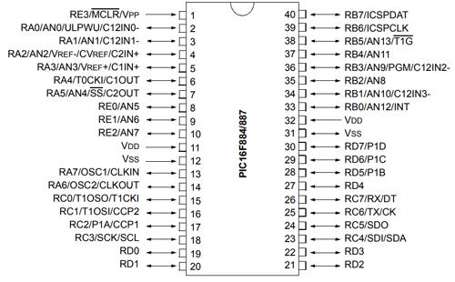
ThisisanLCDDisplayintendedforusewithE-blocks. Ithasasingle9-wayD-typeconnectionanda16-character, 2-line alphanumeric LCD display. This enables the device to be linked to the majority of E-Block I/O ports. The LCD displayrequiresserialdata,whichisdescribedintheuser guide below. A 5V power supply is also required for the display. Please avoid exceeding 5V since this will cause harm to the gadget. The ideal source of 5V is the E-blocks Multi programmer or a 5V fixed regulated power supply. The clever alphanumeric dot matrix display (16 x 2) can show224distinctlettersandsymbols.Pages7/8includea complete list of the characters and symbols (note these symbols can vary between brand of LCD used). This pamphletcontains all ofthe technical detailsfor attaching the device, which requires a single (+5V) power source. TheLCDisutilisedtodisplaythemessagetotheconsumer inthiscase.
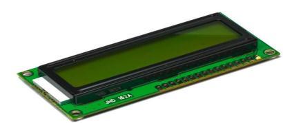
3.2.RELAY:-
A relay is a type of electrical switch. Their internal mechanical switching mechanism is often powered by an electromagnet (coil) (contacts). When a relay contact is open, the power to a circuit is turned on when the coil is energised. Relays enable one or more higher current circuits to be controlled by a low current circuit. To connect the control switch to the relay, thinner wires can be utilised, saving weight, space, and money. Relays allow electricity to be directed to a device over the shortest possibledistance,resultinginlessvoltageloss.TheTrigger voltageisthevoltagenecessarytoactivatetherelay,which changes the contact from Common->NC to Common->NO. Our relay has a 5V trigger voltage, but you can also get
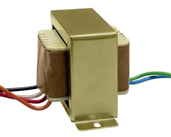
By boosting the electrical current, step-down transformers reduce the voltage entering to the site. This
isaccomplishedbyconvertingthehighinputvoltageinthe main winding to the lower voltage required in the secondary windings. Step-down transformers are often used in electricity distribution networks to convert a power station's output voltage to that required for high voltage transmission and back down again for usage in homes,industries,andoffices.Thestepdowntransformer is utilised in this case to lower the high voltage to low voltagewhileincreasingtheelectricalcurrent.
3.6. POTENTIOMETER:-
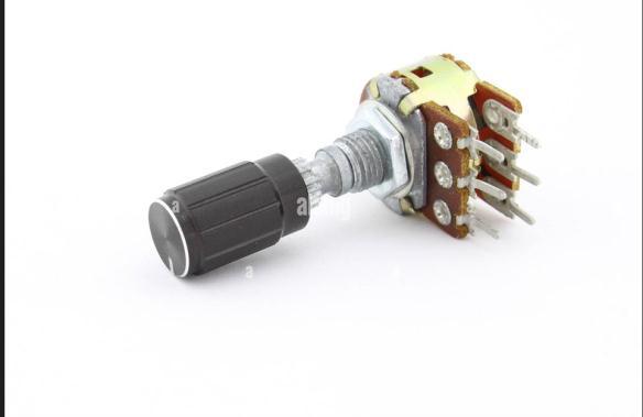
The potentiometer is a device used to measure unknown voltages by comparing them to known voltages. They are passive devices, which means they don't require any electricity or extra circuitry to work. In this case, the potentiometer serves as a load or current source. Potentiometers are seldom used to regulate considerable power (greater than a watt) directly because the power dissipatedinthepotentiometerisequivalenttothepower in the controlled load. Potentiometers are made up of a resistive element, a sliding contact (wiper) that moves along the element and makes good electrical contact with one end of it, electrical terminals at each end of the element,amechanismthatmovesthewiperfromoneend to the other, and a housing that houses the element and wiper. A linear slider potentiometer, on the other hand, has a wiper that slides along a linear element rather of spinning. The slider potentiometer has the benefit of providing a visual indication of its setting. While the position of a marker on a rotary potentiometer knob indicatesthesetting
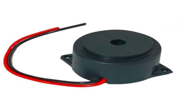
3.5. PIEZO BUZZER:-
A piezo buzzer is an electrical device that produces a tone, alert, or sound. The primary function of this is to transform the audio signal to sound. In general, it is powered by DC voltage and is utilised in timers, alarm devices, printers, alarms, computers,and so on. It may make various sounds such as alert, music, bell, and siren accordingonthedesign.Thebuzzerisused toinformthe usersincetheusermaybecomehasdistractedbytheirjob and miss the message. It is a modest yet effective component for incorporating sound into our project/system. Because of its tiny and compact 2-pin shape, it may be readily utilised on breadboards, Perf Boards,and evenPCBs, makingita popularcomponent in many electronic applications. Because of the internal oscillatingcircuit,itmakesabeepsound.Thisbuzzermay beutilisedbysimplyconnectingittoa4Vto9VDCpower supply.
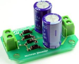
3.7. BRIDGE RECTIFIER:-
Thebridgerectifierisaformoffull-waverectifier that converts alternating (AC) current to direct (DC) current by using four or more diodes in a bridge circuit topology.
4. WORKING OF PROPOSED METHOD:-
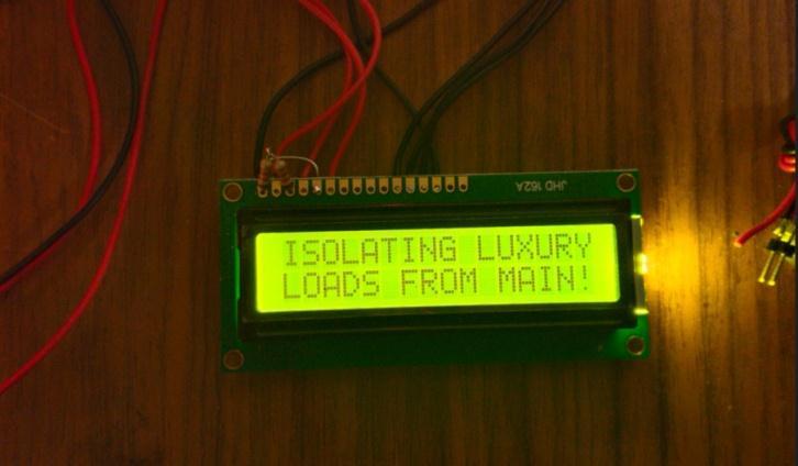
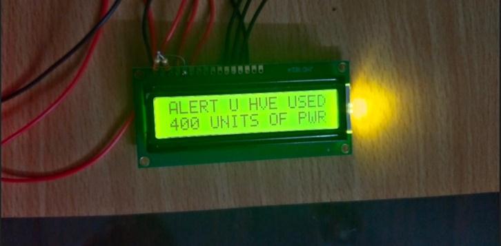
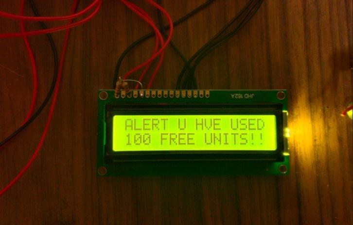
Todesignthesystemto usethe energyintheeffective manner to reduce the electricity charges. This system will continuously monitors the power consumption by the homeappliances.Itcalculatestheunitpowerconsumption in order to alert the consumer when they are about to cross the current slab rate.When the user is very close to crosss the current slab rate it will send message to user and alert the user to reduce the power consumption. The step down transformer is used to reduce the high voltage tolowvoltageandincrease theelectrical current.Herethe bridge rectifier is used to convert the alternating current to direct current and the capacitive filter is used to filter the unwanted voltage and it send to the voltage divider.The voltage divider is used to divide the high voltagetolowvoltage.Thepotentiometerisactasaloador current.If theuser reaches 100unitsit will sendthealert message to the consumer with buzzer sound. And it reaches 400 units it will send the warning message to the consumerwithbuzzersound.Oncethepowerconsumption is about to cross the current slab rate, which is 450 units the auxilary line is automatically cutoff and the status is updated to the consumer by message and the buzzer sounds continuously to warn the consumer.The relay is usedto cutthehighcurrent loadlines.Andthe resultscan bedisplayedintheLcddisplaytotheconsumer.
5. RESULT:-
Theresultscanbedisplayedinthelcddisplay.The outputforattaining100unitsisshowninthefigurebelow.
6. CONCLUSION:-
By using this Power consumption within the slab rates can be maintained by continous tracking.When the power consumption is about to cross the current slabrate the auxiliary load line will be cutoffed automatically is executed.Themessagescanbedisplayedinthelcddisplay.
7. REFERENCES
[1] IoT based Energy Meter with Smart Monitoring of Home Appliances Vishnukant V. Gavhane;Mayuri R. Kshirsagar;Ganesh M. Kale;Shubham Katangle;S.B. Deosarkar 2021 IEEE journal paper on Convergence in Technology(I2CT)
[2] Smart electricity monitoring and analysing an IoT system with a mobile application . A. I. R. Fernando, M. D. R. Perera2020 IEEE journal paper on Smart computing andsystemengineering.
[3]Mohannad Jabbar Mnati, Alex Van den Bossche and Raad Farhood Chisab “A Smart Voltage and Current
Monitoring System for Three Phase Inverters Using an AndroidSmartphoneApplication”,Sensors2019,17,872
[4] ] Karthik Subramanian, Shantam Tandon, “Power factor correction using capacitors & filters”, International JournalofEngineering&Technology,7(2.12)(2019)23423
[5] Ismail Harnekar Aadam, B. Patel Gaurang Kumar, “Automatic Power Factor Correction by Fine Tuning of Graded Capacitors”, International Journal of Advance Research,IdeasandInnovationsinTechnology.(Volume3, Issue6)2017