Determination of Flutter Angle by Resolving Effective Gyroscope Couple to Retard Air Resistance in Aeroplane
Srivardhan.R
1 , Vishal.S2 , Balasubramanyam D.B3 , Dharshanaa G.B41Student, Dept. of Mechanical Engineering, Chennai Institute of technology, Chennai, India.

2Student, Dept. of Mechanical Engineering, Chennai Institute of technology, Chennai, India.
3Student, Dept. of Computer Science and Engineering, Chennai Institute of technology, Chennai, India.
4Student, Dept. of Computer Science and Engineering, Chennai Institute of technology, Chennai, India.
Abstract
The paper discusses how to effectively resolve a gyroscope couple for a three-dimensional working model in order to achieve the deflection in all three coordinates in a simple and straightforward manner. Furthermore, the flutter is programmed to perform tilt of it in order to include proper uplift and displacement is tested with the aid of a finite element model in an efficient manner and adaptive to incorporate and identified and resolved
Key Words: Flutter,deflection,resistance,effective couple,magnitude,
1. INTRODUCTION:
The primary objective of this research is to determine the impact of a vast wing-tip fin, which is an oversized version of contemporary winglets, on flutter speed. The dissemination of information concerning static aeroelastic behaviour, which could also alter the excellent traction of vertical surfaces mounted only at tip,isamajorpriority.Toaccomplishthis,thenaconcise overviewofwingletflutterisexamined.Theresultsfora generalconfigurationusingastraightforward modeland a higher-fidelity flutter model are then presented. Winglets are used by a number of modern commercial aircrafttomitigateinduceddragatyachtcharterspeeds. Flutter is not a concern with these aircraft since they have been certified following a thorough analysis, test, and certification process Presented as 53rd AIAA Structures. However, since the gyroscope is a critical component of the navigation system and is frequently used to achieve the measurement of the system's attitude, there is very little archival research on the impactofwingletsonflutter.
Gyroscopestabilityhasa bigimpactonthetransponder, anditplaysabigpartinstabilitycontrol,navigation,and assistance. Correspondingly, it is vital. The navigation system is severely influenced by its stability. Consequently, it's pivotal to research gyroscope fault diagnosis advanced technologies. Due to the gyroscope malfunction, the redundancy of the remaining operating gyroscope cannot appease the parity equation for fault
***
diagnosisduringthechronicconditionsofthenavigation system.Aseitheraconsequence,othermethodsmustbe employed to diagnose gyroscope faults. It is challenging to create concise computational equations for the measurement and control components of dynamical system, and the existing analytical redundancy method struggles to satisfy the requirements of fault diagnosis. . The researchers suggested a fault diagnosis and diagnosis based on signal processing and knowledgebased methods to address the aforementioned limitations. Information fusion and wavelet analysis are twocommontechniquesbasedonsignalprocessing.
2. MATERIALS AND METHODS:
The benefit of a gyroscope condition monitoring technology based on wavelet transform is that it can undertake time-frequency comprehensive analysis on sensor signals, which can rapidly and aptly diagnose faults.[3]Thequantificationinformationformulti-sensor systems is complex and diverse, so the information fusion method must also be reliable, fault-tolerant, and resilient.Anoteworthyoutcomewasattained.
2.1 Configuration of redundancy in gyroscope
Two or more identical gyroscopes can be utilized for redundant configuration design in the stance measurement system to complete the system attitude measurement 20-21. This study employs three redundant three-degree-of-freedom gyroscopes, each of which is capable of measuring the angular velocity of three orthogonal axes. When a gyroscope's measured valueforoneofitsaxesis
Specifythestandarddeviationasfollows:
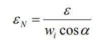
Fig. 1 gyroscoperedundancyconfigurationscheme
The data packets of the three axis of thegyroscopes are A, B, and C, respectively. The multiple evaluation axes of thegyroscopeAarex1,y1,z1,;thethreemeasuringaxes of the gyroscope B are X2, Y2, Z2; the three measuring axes of the gyroscope Care X3, Y3, Z3. The arrangement of a three-axis gyroscopes and the arrangement orientations of the x, y and z axes of every three-axis gyroscope are depicted in Fig. 1. There are nine hypersensitive axes in the setup method, and the robust strong support system parameters of the three-axis gyroscope.
2.2 Stability in upright condition
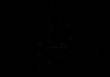
Thesimplestwaytoutilizeagyroscopetostabilizeflight motions is to take advantage of the natural dynamics of the vehicle. In previous work [1] it was shown analyticallyandmgθxfdxXxZxYtable(1):Modeland axis convention for the robotic fly. The vehicle state is given by three quantities, the rotation angle θ, the rotation velocity ω, and the lateral velocity in body coordinates v. A lift force fl generated by the flapping wings acts at a distance right away from the center of mass and along the body-z direction, an aerodynamic dragforceforwardactsata distancerightwardfromthe CM,[4] and the gravitational force mg acts at the center of mass. The right-handed axis convention for world coordinates is shown, with y pointing into the paper. A feedback controller applies a control torque (τ) by alteringbaselinewingkinematics.
Fig. 2 coupleforcesactingonthegyroscope configuration
2.3 development of model:
Designers picked this aircraft due of its vast documentation.Twoanalyticalmodelswerecreated.The first and simplest model is a Rayleigh–Ritz beam model, inwhichthewingandfincomponentsarebothmodelled as homogeneous beams with bending and torsional degrees of freedom. A quasi-steady aerodynamic approximation for the unsteady forces and moments offersanairspeeddependentaerodynamicstiffness.This type restricts the tip-fin to be installed in a vertical position only. Wing deformation involves two presumed displacement modes, one for bending and the other for torsion. The displacement at any point on the wing surface,wx;y; t,iscomprisedofupward bendingatthe wing shear centre, w SC, and twist about the shear centre, θ[2],[1]. In terms of the wing spanwise coordinate, y, measured outward from the cantilevered wingroot,andthechordwisecoordinate,x,measuredaft fromthewingelasticaxis,thedisplacementofanypoint onthewingis
Table 1.Parametersofgyroscopiccouple
w₁=Wwing (x,yw,t)=wsc (yw,t) xβ(yw,t) (2)
The tip-fin motion is made of two separate forms of motion. The first is designated as w2 and is due to outof-plane fin bending and torsion, a function of the fin spanwise coordinate, yf, and the fin chordwise coordinate,xf.
w₂=wf(xf,yf,t)=Wfin,SC-Xfβf (3)
The wing mass is given by a sequence of concentrated mass components whose distance from the spar may be modified to regulate the chordwise centre of gravity (c.g.) location. The tip-fin mass and stiffness characteristicsaresimilarasthewing;tip-finlengthand cant angle are parameters for this model [5]. The geometry and material properties for the finite element model were identical to the Rayleigh–Ritz, wing model, but a doublet lattice, precarious aerodynamic forces framework replaced the streamlined quasistatic aerodynamic representation, whereas the assumed structural deflection modes were replaced by a finite elementstructuralmodel.
The mass, stiffness, and aerodynamic force matrices are calculated using expressions for the wing/tip-fin kinetic energy, the wing/tip-fin strain energy, and the virtual work done by the quasi-steady aerodynamic forces acting on the wing and tip-fin. The result, using Lagrange’s equations and assuming harmonic motion, is afourthordereigenvalue.
2.4 Feedback from motion capture
Figure 3 illustrates that, with suitable tuning of controller gains and trim settings, the robot was able to bear the extra weight and lift off and hover around the intended setpoint location [X, Y, Z] T = [0.04362, 0.04988,0.05866]Tmutilizingmotioncapturefeedback. Its mean location for the 2 s time after attaining the requiredheightwas[0.053,0.005,0.062]Tm.
2.5 Feedback from angular velocity
After verifying the angular velocity estimate of ω from the gyroscope accurately matches the ground truth measurement from motion capture, with lower 0.08
0.08 y (m) x (m) z (m) (m) Figure 3: Plot of hovering flighttrajectoryinwhichgyroscopesuppliedanestimate of the angular velocity ω. Other characteristics are the same as in Figure (4), [7]. delay, we included this estimate into the hovering attitude controller. Figure 8 demonstrates that the robot accomplishes hovering flight,flyingnearthespecifiedpoint,maintainingamean position of [0.04362, 0.04988,0.05866] N- m and equivalenterror.
2.6 Control algorithm
This code accepts the resolver components x, y, and z from the gyroscope as inputs and passes them to the function.Forthepurposeofpredictingflatterangles,the function makes use of conditional statements. Conditionalstatementschangethebehaviourofthecode based on a set of inputs. The angle of deflection in a coordinate is returned by this function. A set of values determines specific commensuration. A deflection of 13 degreesin the x-axisisobserved whenthex component is subject to a force of 0.04362, and y and z experience forces less than 0.005 and 0.062 respectively. Force of 0.04988 in the y component causes the y coordinate to deviate by 8 degrees while the force is less than 0.053 and 0.062 in x and z. A force of 0.05866 in the z componentcausesa 12-degreedeflection wherex and y remainlessthan0.053and0.005respectively.Whilethe
ycomponentexperiencesthesameamountofforcebutx andzdonotmatch0.053and0.062,a5-degreedeviation is observed. The inputs are considered to be invalid if theydonotpassanyoftheaboveconditions.
defflatterAngle(inp):
x,y,z=inp[0],inp[1],inp[2]
ifx==0.04362andy<0.005andz<=0.062:
return13#deflectioninx-axis
elifx<=0.053andy==0.04988and z<=0.062:
return8#deflectioniny-axis
elifx<=0.053andy<0.005andz==0.05866:
return12#deflectioninz-axis
elifx!=0.053andy<0.005andz!=0.062:
return5#deflectionforspecialcase
else:
return'InvalidInput'
n=int(input())
foriinrange(n):
inp =list(map(float,input().split()))
print(flatterAngle(inp))
3. ANALYSIS
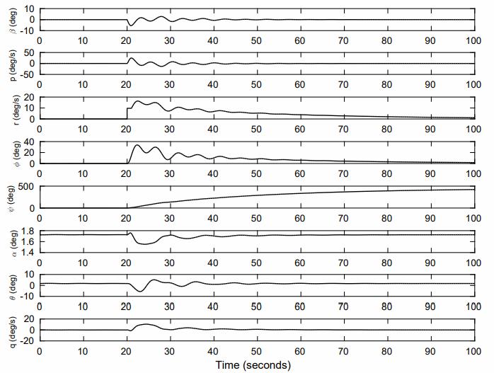
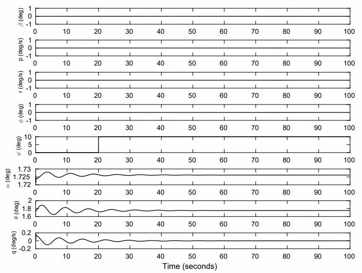
The flight utilising solely motion capture estimations yieldedameanEuclideandistanceerroroflessthan0.01 m from the setpoint. When the ω estimate from the gyroscopewasadded,themeaninaccuracywasasimilar 0.01 m. For the flight in which gyroscope feedback additionally calculated the attitude zˆ, the inaccuracy roseto0.03m.Aprobablereasonforthemistakeisthat, as can be shown in Figure 4, a clear drift is observable alongthepitch(red)axis,reachinganerrorof6◦(0.1rad) (0.1 rad). This drift, probably emerging because the biggest oscillations occur along this axis due of the forward-backward movements of the wings (Figure 3), would generate a force inaccuracy in the y-direction when the vehicle tilted in response. In addition to showing the 3D trajectory of each flight and comparing the mean location of each flight experiment, we determined the root mean square error (RMSE- Root Mean Square Error) see Figure 4). We predict comparable amounts of RMSE in altitude because coordinates,0.050.0680.12,0.020.040.06,y(m)x(m)
z (m) (m) Figure 5: Plot of flight trajectory in which the gyroscope gave entire attitude feedback in the flight controller,includingbothangularvelocityωandattitude zˆ.Inthisflight,thepositionerrorwassomewhatgreater thaninFigure(6),presumablydueofdriftintheattitude estimate. Othercharacteristicsarethesameasin Figure (7).thealtitudecontrolleroperatesindependentlyofthe attitude controller and gets the identical values in all testing,ascanbenotedinFigure8.RMSEiscomparable between the motion capture-only experiment and experimentinwhichthegyroscopecalculatedωforboth x-position, where the errors are 1.17 cm and 1.39 cm, respectively, as well as for the y-position, where the errors are 1.26 cm and 1.05 cm, respectively. The RMSE of the lateral position of the aircraft using attitude estimatefromthegyroscopeismuchbiggerat2.72cmin x−position and 2.95 cm in y-position. [7] Given that the robot had trouble regulating its pitch angle and wanderedawayfromthesetpositionduringflight,these figures are not surprising. These results demonstrate thatestimationsfromthegyroscopemaybereplacedfor those from the motion capture system and still retain stability and control of the vehicle despite its quick and unstabledynamics
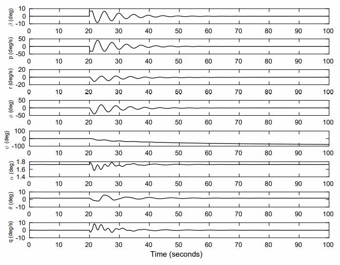
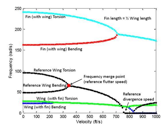
Figure 5 displays typical flutter results from the Rayleigh–Ritzquasi-steadymodelwitha90degreescan’t angletip-finlength (Lf),halfthewingsemi-span(L).The set of black lines plot the real sections of the system eigenvalues for the wing without a fin. Flutter is representedbythecoalescenceofthe wing-bendingand torsion modes. When the fin is added to the wing, four eigenvalues occur and there are two separate frequency coalescence curves. One of these curves will merge at a lower flutter speed, depending on the fin size compared to the wing. The lower set of curves, blue and green, demonstrate flutter initiation caused predominantly by wing bending torsion interaction. This motion is adjusted bythetip-fin.The secondset ofcurves, the top setofblueandredlines,mergeatagreatervelocity;this
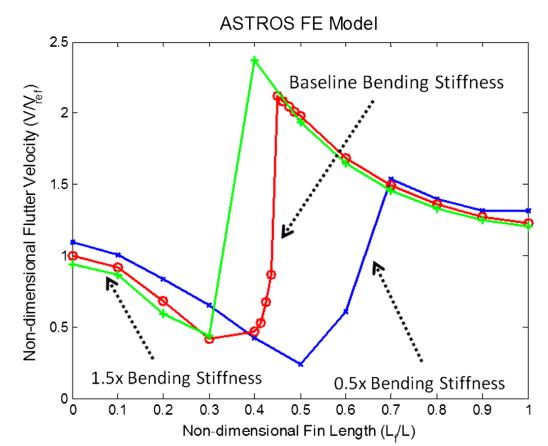

interactionisprincipallybetweenthetip-finbendingand torsionmotionmodifiedbywing-tipmotionatthetip-fin base connection. The relative placements of these two coalescence sites alter with fin length. In this scenario, theflutterspeedisloweredbytheinsertionofthetip-fin. Figure 7 illustrates flutter data from the two models illustrating how flutter speed varies as tip-fin length growswhenthetip-finisvertical.Thefindingsdisplayed inFig.8arealsostandardisedtothespeedspredictedby eachmodelforthewingwithoutthetip-fin.TheASTROS model always forecasts higher flutter speeds than the quasistatic model. The ASTROS model suggests that flutterspeedisreducedwhenevenalittlefinisaddedto the wing, however the quasi-steady model shows a modest increase in flutter speed for small fins. Both models reveal that as the fin length grows, the flutter speed is lowered to less than half of the no-fin value. These results are similar with the previously reported research in [5], [9], and [10] when the fin is very tiny. Both models imply that there are two flutter modes and indicatethatthereisafluttermodeswitchingoccurrence near Lf ∕L 0.5 when the tip-fin gets large enough to triggertheflutterinstability.
4.1 Static aeroelasticity–directional stability derivatives
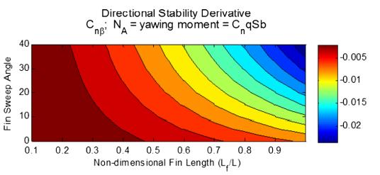
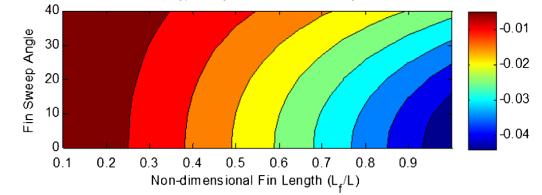
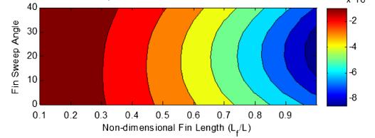
The value of the lift-curve slope of a stiff swept surface drops approximately in relation to cos(Λ).] This compensates for this drop in side-force caused by sideslip.[10] The flexible fin side-force stability derivativedropsaswell,butthefigurealsoindicatesthat at moderate sweep angles the adjustable fin is more effective, butasthefinissweptthepliablesurfaceisfar less effective. At increasing sweep angles, fin yielding coupled with fin sweep diminishes the efficiency of the fin.[6]Theyaw-momentflexiblederivativedemonstrates similar behaviour to the flexible side-force derivative. However, observe that the stiff stability component initially decreases (greater stability) but the curve has a local minimum at approximately 20 deg. As the fin is swept, the fin lift-curve slope reduces as the moment arm between the fin aerodynamic centre and the fuselage centre of gravity grows. Initially, the moment armincreaseishigherthanthelift-curveslopedrop,and thereforethefinoffersmoreyawstability.However,with bigger fin sweep angles, as sweep angle increases, fin bending coupling with fin sweep diminishes the efficiency of the fin. The hard surface yaw components for the larger, longer fin alter in a similar method to the smallerfinrigidyawderivatives.However,thecrossover (the point when the flexible surface becoming less efficient than the rigid surface) takes place at a lower sweep angle. Also, for high sweep angles, 35 to 45 degrees, the shorter fin’s flexible side force component magnitudeisbigger(moreadverse)thanthelargerfin’s. Based on the sweep angle the fin, this could be concern for vehicles dependent on tip-fins for directional stability
5.0 CONCLUSION:
modelbasedonflutter
Placingfinsonwingtipsasasubstituteforaverticaltail presents two aeroelastic challenges, one dynamic, the otherwillbestatic.[8]Theresultsreportedinthispaper demonstrate that the tip-fin size, notably the tip-fin length, and its cant angle are essential design features that affect flutter speed. The user is reminded that the boundary conditions adopted for these experiments preclude the influence of body freedom or antisymmetricmodesofflutter.Smallfinsaimtolimitflutter speed whereas mode switching may allow very lengthy fins to improve flutter speed. Static aeroelastic effects also influence vehicle directional/yaw stability, largely via variations in lifting surface efficacy, a well-known phenomenon for swept and upswept flight controls. These effects are likewise governed by tip-fin levels equivalenttothewingsizeandalsobywingsweep.
6.0
REFERENCE:
[1] Kiyan, R.; Kim, S.K.; Kim, B.Y. Bidirectional singlemodeEr-dopedfiber-ringlaser.IEEEPhotonicsTechnol. Lett.1996, 8,1624–1626.[CrossRef]
[2] Cai, H.; Zhang, H.; Zheng, Y. Soft Magnetic Devices Applied for Low Zero ExcursionRing Laser Gyro. IEEE Trans.Magn.2007, 43,2686–2688.[CrossRef]
[3] Mignot, A.; Feugnet, G.; Schwartz, S.; Sagnes, I.; Garnache, A.; Fabre, C.; Pocholle, J.P. Single-frequency external-cavitysemiconductorring-lasergyroscope.Opt. Lett.2009, 34,97–99.[CrossRef][PubMed]
[4]Schwartz,S.;Gutty,F.;Feugnet,G.;Loil,É.;Pocholle,J. Solid-state ring laser gyro behaving like its helium-neon counterpart at low rotation rates. Opt. Lett. 2009, 34, 3884–3886.[CrossRef][PubMed]
[5]Hurst,R.B.;Stedman,G.E.;Schreiber,K.U.; Thirkettle, R.J.; Graham, R.D. Experiments with an 834 mring laser interferometer. J. Appl. Phys. 2009, 105, 113–115. [CrossRef]
[6]..Elliott-Laboratories . The Anschutz Gyro-Compass and Gyroscope Engineering. Wexford College Press; Kiel, Germany:2003.pp.7–24.[GoogleScholar]
[7] Honeywell. [(accessed on 24 June 2017)];Available online:https://aerospace.honeywell.com/en/products/ navigation-and-sensors/inertial-measurement-units
[8] King A.D. Inertial Navigation Forty Years of Evolution. GECRev. 1998;13:140–149.[GoogleScholar]
[9]..Inertial Labs. [(accessed on 24 June 2017)];Available online:https://inertiallabs.com/ahrs.html
[10] Ezekiel S., Arditty H.J. Fiber-Optic Rotation Sensors and Related Technologies, Proceedings of the First International Conference MIT, Cambridge, MA, USA, 9–11 November1981. Springer-Verlag;Heidelberg,Germany
[11] Flutter and Directional Stability of Aircraft with Wing-Tip Fins: Conflicts and Compromises | Journal of Aircraft. (2013, March 30). Journal of Aircraft. Retrieved January29,2023,