International Research Journal of Engineering and Technology (IRJET)
e-ISSN: 2395-0056
Volume: 09 Issue: 09 | Sep 2022
p-ISSN: 2395-0072
www.irjet.net
Antenna Design for 4x4 MIMO 5G Communication Kalpita B Velip1, Sangam Borkar2 1Student, Dept. of Electronics and Telecommunication Engineering, Goa Engineering college, Goa, India.
2Assistant Professor, Dept. of Electronics and Telecommunication Engineering, Goa Engineering college, Goa, India.
---------------------------------------------------------------------***--------------------------------------------------------------------and adaptable because it may be positioned wherever is Abstract - The design presented in the paper for the 5G
necessary to meet impedance. In this paper a single basic structure of Microstrip patch antenna was considered for designing. The design of a 2x2 and finally 4x4 antenna system with multiple single element antennas were placed compactly in a MIMO configuration.
application (5G NR N78 Band) at the operating frequency 3.5GHz of a patch antenna with U shaped slot was investigated to realise a structured 4x4 MIMO antenna. To widen the bandwidth U-shaped slot was cut out on the microstrip patch antenna that was coaxially fed. FR4 material was used as the dielectric substrate in designing with relative permittivity 4.4 with a height of 1.6mm and loss tangent 0.02. The antenna model was designed and analyzed using HFSS software to obtain a bandwidth of 250 MHz with good performance parameters like VSWR, Gain, Reflection coefficient and Impedance. The parameters and analysis have been added in this paper.
2. DESIGN OF THE ANTENNA In-depth study has recently been conducted to improve bandwidth, gain, and offer size utilizing a variety of strategies. These methods include the use of substrates with reduced dielectric permittivity, air-filled dielectric media, thicker substrates, and slot antenna architecture.
Key Words: Microstrip, 5G NR N78 Band, U-Slot, MIMO,
Gain can be gained by loading a certain slot on the patch element of the antenna that conducts, which results in a smaller antenna and increased bandwidth. When slots are introduced onto a conducting patch element, the excited patch surface current channels might meander, which lowers the resonant frequency and results in a smaller antenna than a traditional microstrip patch antenna at the intended frequency.
HFSS.
1. INTRODUCTION The technology of MIMO (Multiple-input multiple-output), one of the key components playing substantial role in the 5G system of communication can greatly boost spectral efficiency without using additional power. 3GPP (3rd Generation Partnership Project) recognized many licensed and also unlicensed bands which form a wide bandwidth from 3.3GHz to 5GHz as the combination of 5G NR bands N77 (3.3–4.2 GHz), N78 (3.3–3.8 GHz) and N79 (4.4–5 GHz) [2]. The 5G sub-6 GHz spectrum has NR bands N77/N78/N79 its key constituents. The main method for improving all facets of wireless communications is MIMO. It has a significant impact on 5G technology and is changing how everyday people engage with these technologies. By implementing 5G New Radio (NR), data can reach more users and be accessed by more people at the same frequency and time rates. A light-weight and smaller sized antenna is probably recommended to enable the high mobility required for a wireless equipment to communicate. Microstrip antennas that compact enough are among the best tools for this job. Due to their low cost and planar form, microstrip antennas have been extensively well used in modern systems. Cutting a U-shaped slot in the patch of the rectangular patch antenna that is coaxially fed is one way to increase the bandwidth. The finite ground plane and Ushaped slot are employed to produce excellent impedance matching and expand the bandwidth [4]. Due of its benefits, our design takes into account a U-shaped slot on the patch antenna's rectangular shape. For our design, we took into account the coaxial probe feed approach because it is simple
© 2022, IRJET
|
Impact Factor value: 7.529
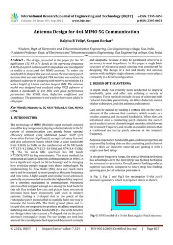
Antenna impedance, bandwidth, gain, and size properties are improved by loading slots on the conducting patch element with a thick air dielectric material and igniting it with a single coax feed setup. In the given frequency range, the coaxial feeding technique has advantages over the microstrip line feeding technique for antenna characteristics. Overall, coaxial feeding produces superior outcomes. compared to micro strip line feeding, ignoring gain, for all antenna parameters. In Fig. 1, Fig. 2 and Fig.3 the rectangular U-slot patch antenna's geometry which is proposed above is shown.
Fig -1: HFSS model of a U-slot Rectangular Patch Antenna
|
ISO 9001:2008 Certified Journal
|
Page 837