TRANSMISSION LINE HEALTH PREDICTION SYSTEM IN HVDC AND HVAC LINES
Bazila Imtiyaz1 , Er Baljit Kaur21Pg Scholar, Department of Electrical Engineering, Institute of Engineering and Technology, Bhaddal, 2Assistant Professor, Department of Electrical Engineering, Institute of Engineering and Technology, Bhaddal ***

Abstract - This presents the study of various configurations in HVDC transmission, converter topologies, and its control analysis. The HVDC system configuration and converter topologies play significant roles in terms of economy, efficiency, and reliability in operation together with existing AC transmission networks. Due to the absence of DC circuit breakers in 2terminal HVDC transmission, any normal and abnormal disturbances are taken care of by its control arrangement. The rectifier and inverters converting stations are crucial parts of DC transmission system provided with current control (CC), voltage control. As the world is evolving very fast the electrical energy necessity to assist the development also peaks up and the systems have to enlarge. This has led to the mutual connection of all types of power systems all over the world. The rising rate of industrialization all over the world makes a huge demand for the consumption of electrical energy. More requirements for electrical energy have led to the search of more efficient methods of electrical energy transmission at higher power and voltage levels. High voltage AC (HVAC) used across the world tends to be fussy over longer distances and it creates various environment issues. Therefore, HVDC use is been propound
Key Words: HVDC, HVAC, Fault Location, Random forest, ANN.,
1. INTRODUCTION
Three-phase PWM VSR systems have gradually gained popularity in the fields of motor drivers, uninterruptible power supply(UPS),renewableenergysystems,andotherenergyconversiontechnologies(Yangetal.,2016;LiandYang,2017; Bueno and Pomilio, 2018; Zhang et al., 2021). However, the majority of renewable energy equipment is constructed in mountainous or isolated regions distant from the shore since the likelihood of sensor failures is relatively high in these environments (Bidadfar et al., 2021). When a failure develops in one of the crucial sensors for the control system, the entireapparatusmaymalfunctionoroperateineffectively(Pengetal.,2018).Therefore,itiscrucialtoaccuratelydiagnose sensorfaultsinthree-phasePWMVSRsystemsinordertoguaranteetheoverallsystem'sdependability.
Hardfaultsandsoftfaultsaretwocategoriesofsensordefectsthatmaybeseparatedbasedonfaultseverity(Huangand Tan, 2008; Li et al., 2011; Darvishi et al., 2021). Damage to sensor components, electrical system short circuits, or open circuits are the main causes of hard failures, and the measured value will fluctuate significantly as a result. Sensor component ageing is referred to as a soft defect. Soft faults do not do as much damage as hard faults, but prolonged use will decrease system efficiency and hasten system ageing (Fravolini et al., 2019). For instance, the closed-loop feedback control will be affected, the control performance will be reduced, the ageing of other equipment will be accelerated, and even safety incidents may result if the fault output signals of the current sensors are utilised as the input signals of the control system. Monitoring early soft fault characteristics allows for the early detection of possible risks, prompt repair, protection of other medical equipment, and assurance of the stability of the entire system. To increase system dependability, a reliable and efficient fault diagnostic approach is therefore especially necessary for sensor defects; it wouldalsobepreferableifthefaultsitescouldbeidentified.
Data-driven and model-basedstrategiescan beusedfor sensor faultdetection and diagnosis (SFDD) (Reppaet al.,2015; Lee et al., 2021). Model-based approaches are typically simple to include into control systems, but they also require the establishment of sophisticated thresholds, making them more challenging to use in other domains, particularly for nonlinearsystemswherefaultmodelsaremorechallengingtoconstruct(Kouetal.,2020;Wangetal.,2020).Withoutthe need to comprehend the fault mathematical model pertaining to the sensor systems, data-driven approaches can just employhistorical data tocreatea black-boxmodel and applya matureblack-boxclassifiertoachievefaultdiagnosis and placement (Li F. et al., 2021; Shi et al., 2008). Consequently, the data-driven methodologies are independent of mathematical models and have drawn the interest of several academics (Ojo et al., 2021). For battery energy storage systems,Leeetal.(2021)developedaconvolutionalneuralnetwork(CNN)-basedFDDapproachtoidentifyandcategorise erroneous battery sensor data. Long short-term memory recurrent neural network (LSTM-RNN)-based thermal defect diagnostics for lithium-ion batteries was developed by Ojo et al. in 2021. This approach is simple to apply and does not
need attention to the intricate mathematical modelling and battery physics parameters. A hypergrid and statistical analysis-basedFDDtechniquewasputoutbyChenetal.(2021a)tohelplocatesensordefectsinwirelesssensornetworks. A distributed SFDD framework was created by Jana et al. (2021), and a fuzzy deep neural network (FDNN) was used to detect and classify the sensor errors. An interval-valued data-driven approach developed by Hajer and Okba (2020) was implemented to identify and pinpoint sensor defects in chemical industrial areas. For micro-electromechanical system (MEMS)inertialsensors,Gaoetal.(2020)suggestedaCNN-basedFDDapproach,inwhichthetime-domainpropertiesof temperature-relatedsensorerrorswereemployedtotrainthedata-drivenFDDclassifier.Haldimannetal.(2020)created a unique approach to detect the fault sensors and suggested a disentangled RNN and residual analysis-based SFDD method. An NN-based fault estimate approach was put out by Chen et al. in 2021b and can produce an accurate assessment of sensor defects. An LSTM-based CSFDD approach was put out by Li L. et al. in 2021, and it can anticipate accelerationresponsesfromobserveddatabyautomaticallylearningdatacharacteristics.Inlightofthepriorexplanation, several fields have successfully diagnosed sensor faults using data-driven methodologies. The historical fault data under bothnormalandfaultmodesmaybegatheredviathesimulationtools,anddata-drivenapproachescanefficientlysetup thenonlinearmodelbetweeninputcharacteristicsandfaultmodes.Toincreasethefaultdiagnosticaccuracyofthewhole diagnosissystem,however,thestudyonfaultdataextractioniscrucial.
We have gained a lot of knowledge from the wonderful work that many academics have done in the area of sensor malfunction identification. Although the artificial neural network (ANN) is a well-liked supervised learning technique, over-fitting can damage both the capacity to generalise and the outcomes of diagnostic tests. The CSFDD classifier is therefore trained using the random forest (RF) method, which is difficult to over-fit due to the inclusion of two randomnesses (random samples, random features) (Roy et al., 2020; Fezai et al., 2021). The RF CSFDD classifier is proposed to be trained using the present fault texture characteristics, which can increase the feature diversity and diagnostic precision. Hard faults can result in significant damage, and the transition from mild faults to hard faults often takes a long period. Soft defects may thus be identified and treated quickly, allowing for timely maintenance of the equipmentandthepreventionofseverefailures.
2. RENEWABLE SOURCES INTEGRATION CHALLENGES
Transmission of large amounts of energy from renewable sources or traditional generators must be accomplished at the highvoltageleveltominimize losses.Asdescribedin[3],greatervoltageforthesameamountofdeliveredpowerreduces the current and, in turn, the loss over the line for both direct current (DC) and alternating current (AC) transmission. Therefore,HVDCismoreefficientsincethereislessenergywasted,andDCeliminatesreactivepower,soonlyactivepower isflowinginaDCline[22].Whentransferringelectricity,adirectcurrent(DC)lineusestwowires,onetocarrythenegative charge(or"-")andtheothertocarrythepositivecharge(or"+").Alternatingcurrenttransmissionusesathree-wireACline (orthreephases).Therefore,HVDCwouldcallforfewerconductorsandasmallerright-of-way,leadingtofewerlanduses andcheaperconductorequipment.
HVDCismostlyusedtotransportpoweroverthesea,whereoverheadlinesarenotpractical,andtoconnectoffshorewind farmstoonshoresubstations.Forthatreasonalone,HVDChasasignificantbenefitoverHVAC.
In the AC situation, the cable is carrying both the load current and the capacitive current because of the AC cables' significant capacitance, which limits the power carried via the cable. A DC cable, on the other hand, solely transmits load current todoawaywithcapacitivecurrent,whichjustifiestheuseofHVDCundersea cablesforpowertransmissionover thesea[23].UnlikeHVAC,whichsuffersfrominductivevoltageloss,HVDCdoesn'thavethisproblem.
Since DC voltage is constant throughout the process, HVDC conductors may transport more power than their HVAC counterparts. On the other hand, AC switches between two different frequencies at regular intervals. Because of this, the root mean square (RMS) is the accepted norm in alternating current (AC), despite the fact that it represents only around 75%ofAC'speakvoltage[22].
3. STABILITY AND FAULT ANALYSIS
In this article, we will examine the significance of system stability in the electric power system and the causes of system instability. In a safe and reliable working electrical system, system stability is the most important factor. Major blackouts can occur in systems due topower system faults. Maintainingsystem stability is of paramount importance in this setting. Wealsodiscusshighvoltagedirectcurrent(HVDC)andhowitcontributestothereliabilityofthealternatingcurrent(AC) system.WealsointroducefailureanalysisintheACsystemwithHVDCattachedandexploretheimplicationsoftheproblem
onboththeACsystemandHVDCindependently.Thissectionconcludeswithadiscussionofwhypinpointingaline'sexact pointoffailureissocrucial.
3.1 STABILITY
"systemstability"isaconditioninwhichcompetingforcesareinastateofbalance[24].Thestabilityofanelectricpower systemismeasuredbyhowwellitcanreturntoitsoriginalstateofoperationafterbeingsubjectedtoaperturbingphysical force.Sincetheloads,generatoryields,topology,andothercrucialoperatingcharacteristicsarealwaysshifting,thepower system architecture is a highly nonlinear system. An upsetting impact may be slight or significant, depending on the circumstances. An unstable electric power system [25] may be the result of voltage fluctuations or recurrence variance affecting the linked power system. Lightning strikes, extreme temperatures, faulty wiring, vandalism, trees falling on transmission lines, plane crashes, too much demand, and car accidents are only some of the additional threats to the reliabilityoftheelectricitygrid.Faultsinthesystemrelatetotheseinstancesofinstability.
When a malfunction occurs, the engine loses synchronism, a fundamental requirement for a power system, if the regular repetitionofswayingmatchestotherepeatedwaveringofthegenerators.
High voltage direct current (HVDC) transmission systems employ the coordinate flow with a more common alternating current (AC) system to transmit electrical power [26]. High voltage direct current lines are used as connectors in AC transmissionsystemsduetotheirreliability,security,andcost-effectiveness.Terminatingcircuitsofthethermistorsputin the two rectifiers and inverters make it much simpler to regulate current on the HVDC side. The AC side is where the switchingandbreakeractionstakeplace(CB).
HVDCessentiallyenablescontroltransferbetweenasynchronousACtransmissionsystems.AnHVDClinkcanhelpstabilise a system against the disruptive effects of rapid power changes [27] because power flows can be flexibly controlled at the staging point between the source and the load. In addition, 24 HVDC enables the trading of intensity across systems operatingatdifferentfrequencies,whichimprovestherobustnessandeconomyofanyelectricsystem.
Given its ability to lessen system instability and increase security, HVDC systems may be more cost-effective for transmissionworkandoperationsovergreaterdistances.HVDCavoidsthemassivefluxesneededtochargeanddischarge the link capacitance during each cycle, making it ideal for underwater power lines. This is why most modern electrical powersystemsbenefitfromhigh-voltagedirectcurrent.
3.2 LOCATION OF FAULT
Inanyelectric system,butespeciallythosewithverylengthytransmissionlines,pinpointingtheexactsiteofthedefectis essential forfixingtheproblem.Ifa firebreaksoutbecauseofa problem,livesmaybelost,propertywouldbedestroyed, andtheelectricitygridwouldbewipedout.Inaddition,interruptionsinpowersupplymightoccurinseveralareasbeyond thefaultspotinthetransmissionandcirculationarrangement[29].Estimatesofsystemvoltagesandflowsmustbe made underfaultconditions,withprotectivedevicesreadytodetectandmitigatefaults'potentiallydisastrouseffects.Faultsare easiertocorrectandtheirrelatedcostsarelessenedwhentheirpreciselocationsareknown.
Engineersworkingonelectricsystemsneedtoputsystemstabilityfirst,thereforetheyshouldgiveseriousthoughttoallof theaforementionedprecautionsbeforecommittingtoafinaldesignandinstallation.Faultsmaybeextremelydangerousto humanlifeandhaveadevastatingeffectontheeconomy.Therefore,areliableandsafesystemiscrucial.
4. RESEARCH METHODOLOGY
4.1 INTRODUCTION TO NEURAL NETWORKS
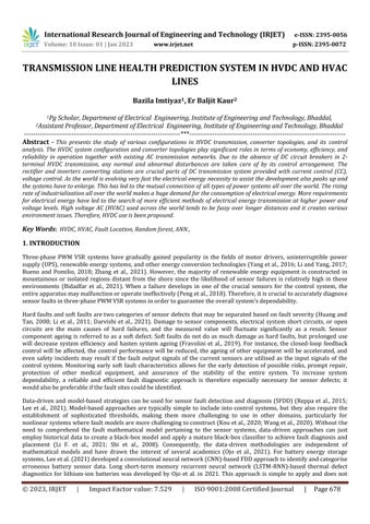
Artificial neural networks (ANNs) may be defined as"a group of simple neuronscoupled together in biologically inspired topologies and arranged in a hierarchical structure" [39]. Feed-forward ANNs, also known as perceptrons, have the followingstructureshownbyFig1.EachsuccessivelayercontainsNimoreneurons,allofwhichreceiveinputfromcellsin the layer below them. All ofthe stimulation information is delivered into the inputlayer. A single non-linearaction on its inputsisall ittakesfora basic neurontogenerateanoutput[40].Eachneuronisassigneda weight,andtraininganANN entails fine-tuning those weights such that they are optimal for the data in the training set. Adjusting the weights of the nodesinanartificial neuralnetwork allowsittolearnfromitsinputsandoutputsthedesiredresult.Inordertotrainthe neuralnetwork,werequireasetofdatacalledthetrainingdataset.Thecapacitytoextrapolatebenefitsfromthisinanew
light[39].TheimportanceofparallelcomputinginANNcannotbeoverstated.Therefore,itcangeneratetheproperoutput foranyinput,evenifsuchinput wasnotprovidedtotheANNduringtraining.Synthesizingthealgorithmfortheadaptive learningprocesswasanotherdifficultyindevelopingANN-basedapplications.
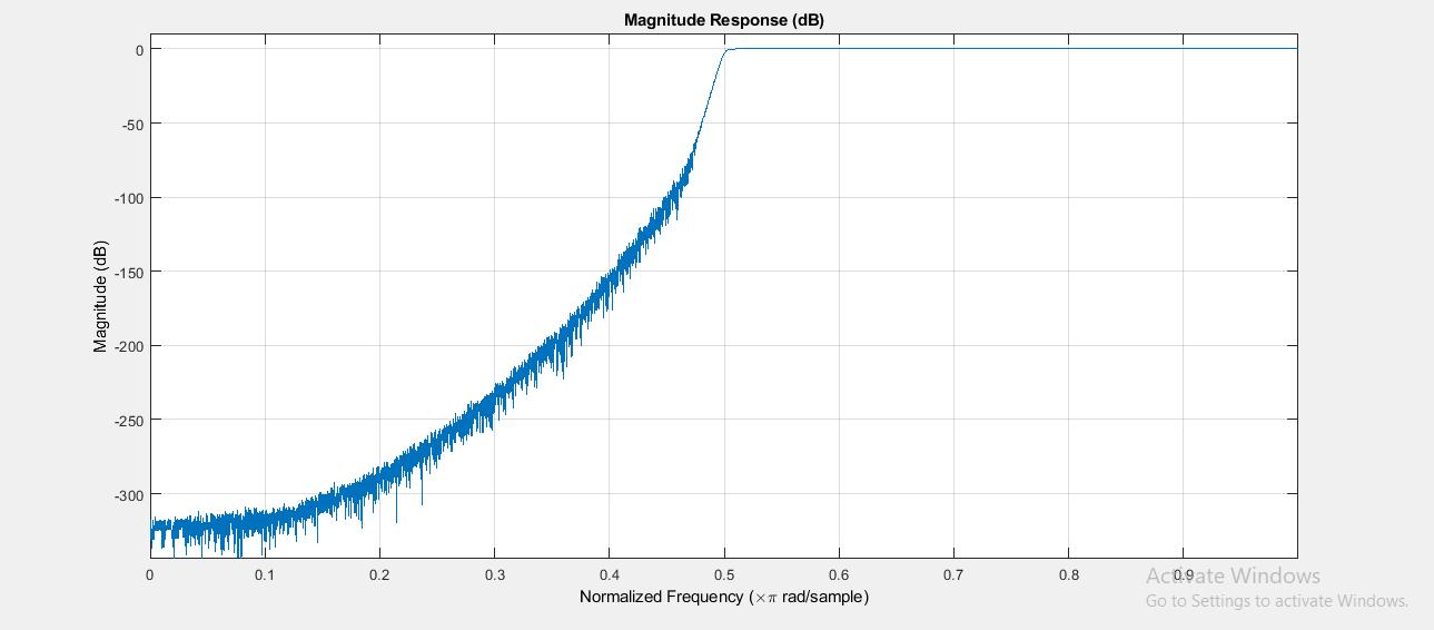
UsinganArtificialNeuralNetwork(ANN)andwavelettransformasafeatureextractiontool,theproposedstudyproposes an effective fault detection and classification technique for high voltage DC transmission lines based on bipolar Current Source Converters (CSCs). Ac sinusoidal voltage, DC voltage, and current data recorded on both poles at the rectifier terminal of the line are input to the Artificial Neural Network model in a suggested technique. When compared to other approaches,theinputsignalsaresampledatonly1kHz.Avarietyoffaultcircumstances,timeintervals,andlocationshave beentestedtoseehowthesuggestedtechniqueperforms.Withfaultdetectiontimesoflessthanhalfcycle,theANN-based fault detector and classification method provided here is 100 percent accurate for all the fault samples that we've examined.TheDeepLearningtoolboxinMATLABTMisusedtodesignandtraintheANNsutilisedinthisthesis.
The dataset is randomly partitioned into training, test, and reference for the various networks. datasets used for testing and validation, with percentages of 70%, 15%, and 15%, respectively. To provide an objective assessment of the ANN duringtraining,thevalidationdatasetisemployed.
Epochsaredefinedasthewholeinputtrainingdataset beingprocessedbythenetworktogetherwiththeupdatingofthe weights and biases involved. The validation dataset is sent via the network and the corresponding error is determined after each epoch. Overfitting to the training dataset can be taken into consideration and the training is terminated if the erroronthevalidationdatasetgrowsaftereachepoch.Thismightbeviewedasanetworkthathasbeenoverlytrainedon acertaindatasetandmaythusbeunabletoaccuratelypredictfreshinput.
Everytrainingwillbedistinctandprovidedifferentoutcomessincetheinitialvaluesoftheweightsandbiasesarecreated atrandom.Additionally,theperformanceofthenetworkanditsstructurearedirectlyinfluencedbythequantityofhidden neurons.Tothisdegree,trainingisperformedagoodnumberoftimesfordifferentnumbersofhiddenneurons,i.e.10,20, 30,40,and50,inordertopreservethebestANN.Theremainingnetworks'hyperparameterslistedintable3.4aresetto thealgorithm'sdefaultsettings,withtheexceptionofthenumberofhiddenneurons.
ThechoseninputcharacteristicsoftheANNsareimpactedbythisdistinctprocedureaswell.Forinstance,unlikethefirst conventional workflow, fault distance and faulty path prediction only use the input characteristics of the phase(s) that have a defect. To this degree, the relevance of the input features for the three separate predictions is monitored to maintainthedeemedmostrelevantonesalone,muchliketheoldapproach.
Additionally, the size of the dataset that may be used is greatly decreased when specialised ANNs are used. In fact, dependingonwhetherfaultdistancegroupH1orH2theybelongto,thefaultypathclassificationANNsmayonlyemploy 408 or 504 of the 6384 simulations that are available. Given that the size of the dataset is a crucial factor in developing reliableandaccuratenetworks,thisisasignificantdownside.AppendixCalsoliststhedimensionsofthedatasetsutilised foreacheachANN.
It is crucial to note that the faulty phase(s) must be anticipated first in the prediction process, followed by the fault distance and then the faulted route, as each forecast relies on the outcome of the other, as illustrated in (Fig. 3.19b). Naturally, it should be noted that this tactic may potentially result in correlation inaccuracies. For instance, using the incorrect ANN for faulty path classification would result from a fault distance prediction error that was too great. Path correlation error is the term used to describe this phenomena. Similar to how incorrect faulty phase prediction will inevitably result in error correlation due to the remainder of the ANNs' utilisation of incorrect input information The chosen input characteristics of the ANNs are impacted by this distinct procedure as well. For instance, unlike the first conventional workflow, fault distance and faulty path prediction only use the input characteristics of the phase(s) that have a defect. To this degree, the relevance of the input features for the three separate predictions is monitored to maintainthedeemedmostrelevantonesalone,muchliketheoldapproach.
Additionally, the size of the dataset that may be used is greatly decreased when specialised ANNs are used. In fact, dependingonwhetherfaultdistancegroupH1orH2theybelongto,thefaultypathclassificationANNsmayonlyemploy 408 or 504 of the 6384 simulations that are available. Given that the size of the dataset is a crucial factor in developing reliableandaccuratenetworks,alsoliststhedimensionsofthedatasetsutilisedforeacheachANN.Itiscrucialtonotethat thefaultyphase(s)mustbeanticipatedfirstinthepredictionprocess,followedbythefaultdistanceandthenthefaulted route, as each forecast relies on the outcome of the other, Naturally, it should be noted that this tactic may potentially resultincorrelation inaccuracies.For instance,usingtheincorrect ANN for faultypathclassificationwould resultfroma fault distance prediction error that was too great. Path correlation error is the term used to describe this phenomena. Similar to how incorrect faulty phase prediction will inevitably result in error correlation due to the remainder of the ANNs'utilisationofincorrectinputinformation
4.2 RANDOM FOREST ALGORITHM
Findingthefault'slocationisthealgorithm'smainobjective,particularlyinmulti-branchdistributionsystems.Findingthe branch(lateralorsection)wherethefailuretookplaceiscrucialbeforemovingon.Thepositionofthefaultisapproximated afterlocatingtheproblematicarea.Thethree-phasecurrent-voltagestatisticsthatwerereceivedareshowninthisfigureas went through a wavelet transform to learn more about the fault that occurred and how to extract features. Fault section identificationandfaultlocationestimateareperformedafteracquiringthebestcharacteristics.
5. RESULTS AND DISCUSSION
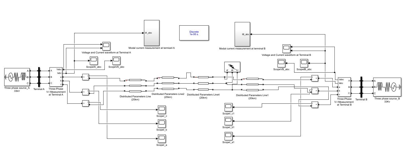
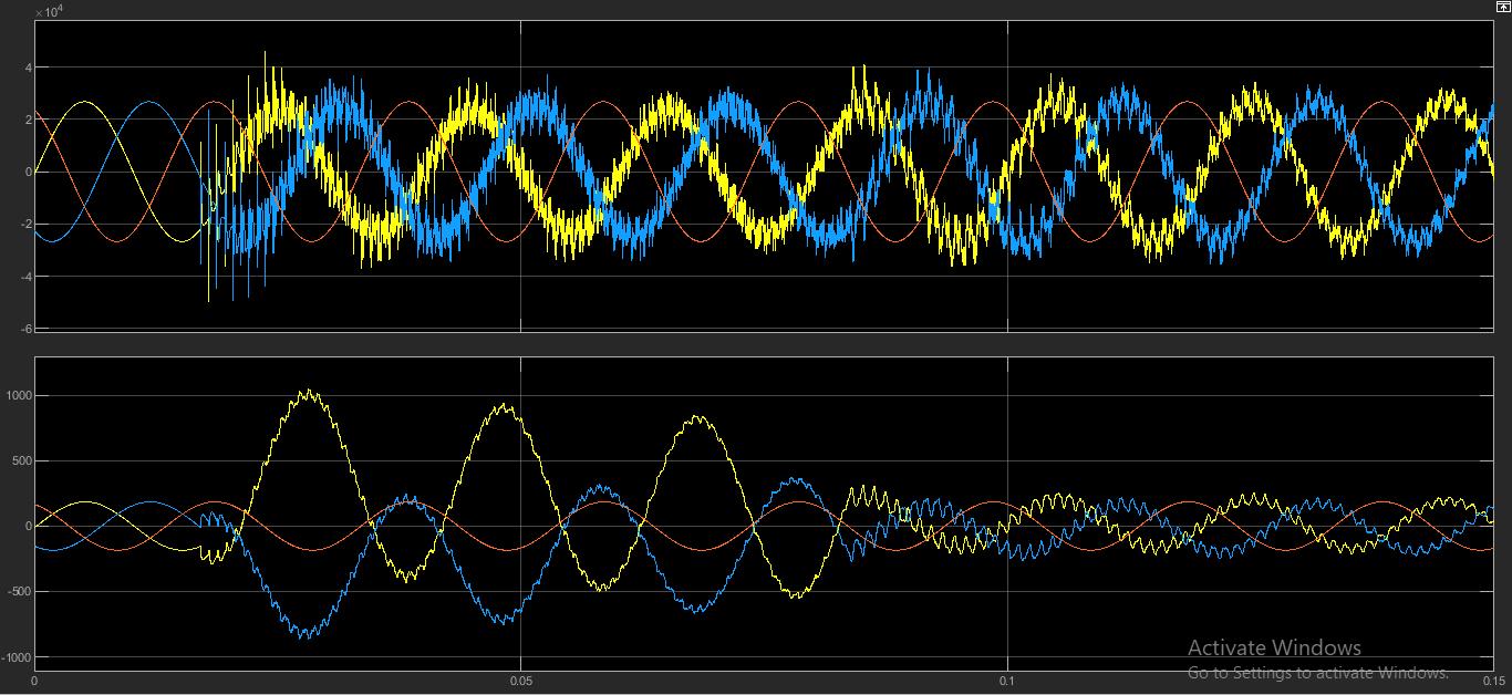
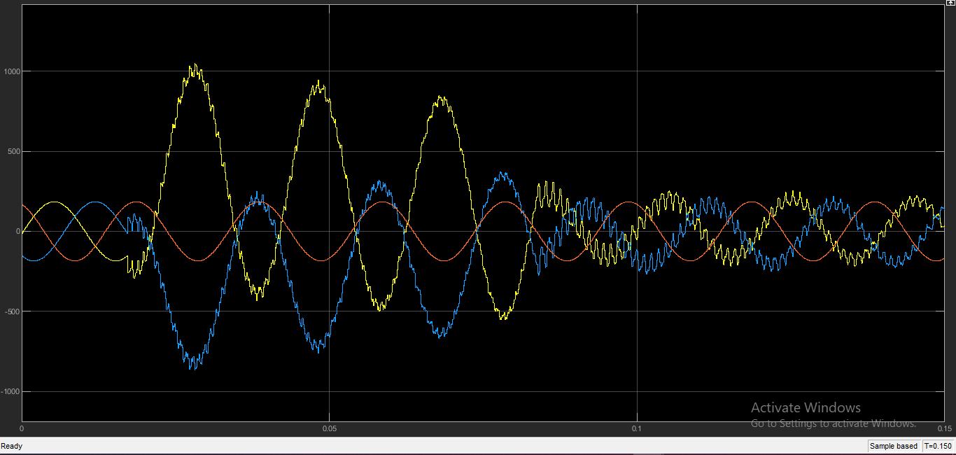
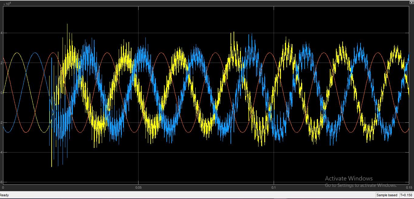
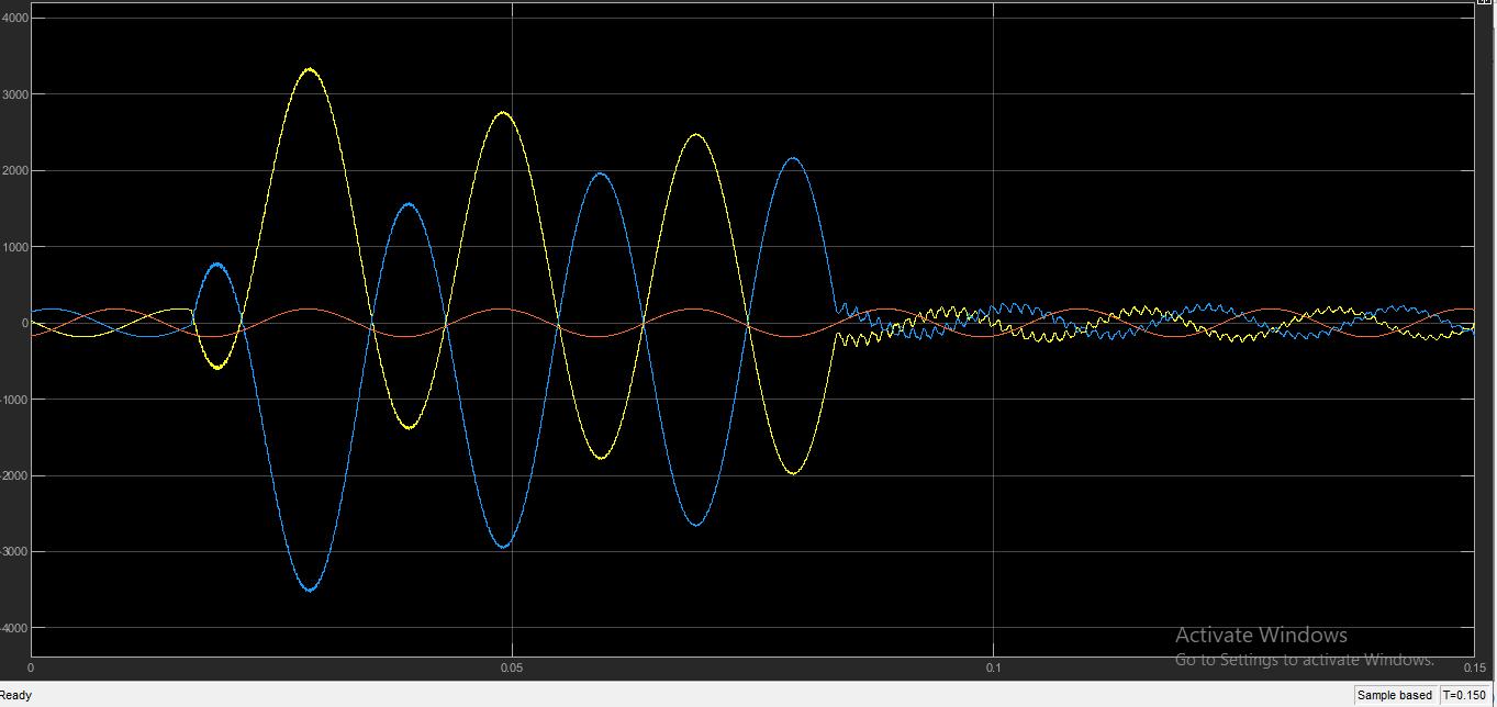
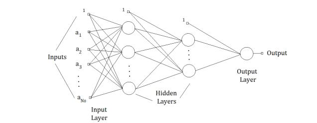
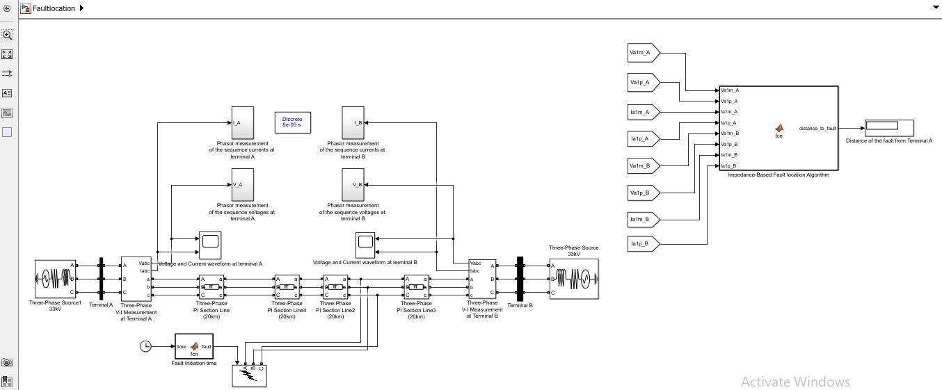
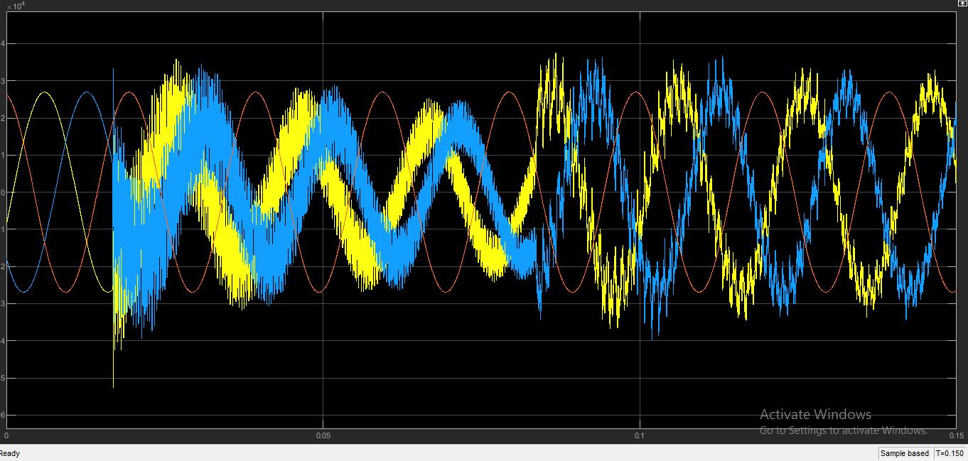
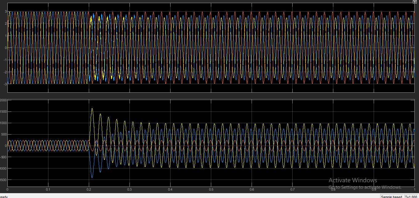
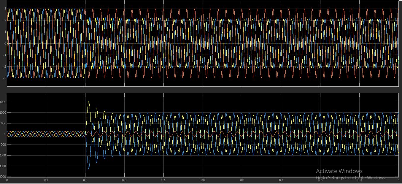
Based on the above simulink diagram the fault location is calculated by placed the fault between the phase A and B , By changing the line length of the transmission line the fault location will change accordingly with reference to A. The fault locationtimeisset at0.2sec,sointhecurrentandvoltagegraph,itshowschangesfromtime0.2seconds.
lengthbetweenAandB
From the above table the line length of the transmission line is changed from 25 km to 475 km respectively and the location of the fault changed with respect to the line length , but the relatives error between all the location remains almostsame
C) RANDOM FOREST
One ensemble method is the random forest F=t1,t2,tt,tt, which consists of a set of unrelated and autonomous decision trees.ModelFcanachieveareliablegeneralizationwiththehelpoftheseuncorrelatedtreessincetheyintroducealittle ofunpredictabilityintothedecisiontrees.Bagging,atechniquethatcombinesbootstrappingandaggregation,isusedto getthesebroadconclusions.Inputfeaturespaceincludingvoltage(v),phaseangle(),currentIandfrequency(f)are part of a training set S=Xm,Ymm(M=1), where XRD (f). The fault location and fault time are both included inside Y, a multidimensional continuous space with the dimensions YRD′. Bootstrap is a subset St of the full training set S, where eachinstanceisrandomlypickedfromthedistributionwithorwithoutreplacement,andMisthenumberofsamples.The numberofinstancesinthefinalbootstrapdataisthesameasintheoriginaldatasetS;however,aboutone-thirdofthe samplesareduplicatedandapproximatelyone-thirdoftheinstancesareeliminated.Togeneratebootstrapsforeachtree, theinputdataisprocessedviaseveraliterations.Aftertrainingandtestingonbootstrapdata,theaggregatedvalueofall theindividualtrees'predictionsiscalculated.
FourexperimentalscenarioswereconsideredfortheevaluationoftheRFRmodelperformance.Theproposedmodelwas assessedbasedontheaccuracymetricinexperiment,whichistheratioofthecorrectlyclassifiedfaultlocationcasesover thetotalnumberofcases.Theaccuracymetriccanbeexpressedas
Accuracy=(TP+TN)/(TP+TN+FP+FN)
where TP denotes a positive result, TN a negative one, FP a false positive, and FN a false negative. The confusion matrix provideduswiththesevalues.Anfurthersetoftestslookedathowwellthemodelestimatedhowlongafailurewouldlast. Duetothecontinuousnatureofthisfeature,differentperformancemeasurements,suchasmeanabsoluteerror(MAE)and meansquarederror(MSE),wereused.TheMeanAbsoluteError(MAE)iscalculatedbyaveragingthesquareddeviations betweentheobservedandexpectedfaulttimes.
MAE=1/n∑i=1n|(yˆ−y)|
The number of cases, n, the actual fault duration, y, and the expected fault duration, y. By averaging the squared discrepancies between the actual fault time and the projected one, MSE penalises for severe inaccuracies while maintainingtheadvantagesofMAE
BycomparingthetwoalgorithmsANNandRandomForestClassificationonthebasisoffaultbetweenthetwoterminalsA andB,Theresultsofthetwoalgorithmsarecomparedasmentionedintableandgraph
6 CONCLUSIONS
TheHVDCtransmissionisperpetuallydevelopedandwidelyusedinrenewablepowerapplications,soithasawideoutlook. This research presents the study and analysis of HVDC transmission system at the time of DC transmission pole to pole shortcircuitfaultandpoletogroundfaults.DCpoletopolefaultischoosetobeanalysedbecauseitisobservedasoneof themostdangerousfaultsinanytransmissionsystem.Thefaultcharacteristicshasbeenstudiedstartingfromtheinstantof faultmomentanduntilitreachesitssteadystatecondition.Itisseenthatduringthistypeoffaultsthesystemconfiguration changes in time. A HVDC transmission system has been simulated by using MATLAB Simulink and the system has been testedinnormalandfaultconditions.
Thistechniqueusestheratioofinstantaneousenergiestopinpointthedefect.Themethodisunaffectedbytheresistanceof thefaulttransitionthankstotheratio.Thisapproachisbasedondetectingtheelectricalamountinformationatbothendsof the DC line to obtains the problem location. It is unaffected by the synchronous clock since it does not depend on measurementtime.
Itisdeterminedthattheapproachisstraightforwardandsimpletoexecute,andthatitisbothaccurate andresilientinits abilitytopinpointproblemsonDCpowerlines.Asaresult,thefindingsofthisresearchhavesomebearingontheproblem of fault localization in DC lines. From the above techniques it is clear that RFC is more accurate than ANN and other algorithms.
REFERENCES
1. .J. -Y. Wu, S. Lan, S. -J. Xiao and Y. -B. Yuan, "Single Pole-to-Ground Fault Location System for MMC HVDC Transmission Lines Based on Active Pulse and CEEMDAN," in IEEE Access, vol. 9, pp. 42226- 42235, 2021, doi: 10.1109/ACCESS.2021.3062703
2. H. Gonzalez-Sanchez, V. Torres-García, D. Guillen and S. Ramírez-Zavala, "Review of fault location algorithms in transmissionlines," 2021 IEEE International Autumn Meeting on Power, Electronics and Computing (ROPEC),2021, pp.1-8,doi:10.1109/ROPEC53248.2021.9667994.
3. DongWang,JianhaoFu,MengqianHou,FengQiao,MengyouGao,Noveltravellingwavefaultlocationprinciplefor VSC-HVDC transmission line,Electric Power Systems Research,Volume 196,2021,107226,ISSN 0378 7796,https://doi.org/10.1016/j.epsr.2021.107226.
4. Heyman,OlofH,Weimers,Lars,andBohl,Mie-Lotte.“HVDC:Akeysolutioninfuturetransmissionsystems”.WEC: N.p.,2010.
5. Vassilios G. Agelids, georgios D. demetriades et.,al “ recent advances in high voltage direct current power transmissionsystems”Murdochuniversity,Australia.
6. http://large.stanford.edu/courses/2010/ph240/hamerly1/images/f3big.gif
7. Billinton. R and Ahluwalia S.D "Incorporation of a DC Link in a Composite Adequacy Assessment-DC System Modeling", IEE Proceedings-C Generation Transmission and Distribution,vol.139,no.3,May1992
8. Mehdi. A,. Kim C H, et al, "A Comprehensive Review of Auto-Reclosing Schemes in AC, DC, and Hybrid (AC/DC) TransmissionLines,"in IEEE Access,vol.9,pp.74325-74342,2021,doi:10.1109/ACCESS.2021.3077938
9. Li,Congshan,etal."ANovelFault-locationMethodforHVDCTransmissionLinesBasedonConcentricRelaxation PrincipleandWaveletPacket." Recent Advances in Electrical & Electronic Engineering (Formerly Recent Patents on Electrical & Electronic Engineering) 13.5(2020):705-716
10. J.Xu,Y.Lü,C.ZhaoandJ.Liang,"AModel-BasedDCFaultLocationSchemeforMulti-TerminalMMCHVDCSystems Using a Simplified Transmission Line Representation," in IEEE Transactions on Power Delivery, vol. 35, no. 1, pp. 386-395,Feb.2020,doi:10.1109/TPWRD.2019.2932989
11. BenaslaM,AllaouiT,BrahamiM,etal."HVDClinksbetweenNorthAfricaandEurope:Impactsand benefitsonthe dynamic performance of the European system." Renewable and Sustainable Energy Reviews, 82 (2019) 3981
3991.
12. Saleem U, Arshad U, Masood U, Gul T, Khan W A and Ellahi A, "Faults detection and classification of HVDC transmission lines of using discrete wavelet transform," 2018 International Conference on Engineering and Emerging Technologies (ICEET),2018,pp.1-6,doi:10.1109/ICEET1.2018.8338615
13. BarsaliS,PoliD,SalvatiR,etal.“Restorationislandssuppliedbygas turbines.”ElectricPowerSystems Research, 78(2016)2004–2010.
14. Dehghani, F.; Nezami, H. A new fault location technique on radial distribution systems using artificial neural network. In Proceedings of the 22nd International Conference and Exhibition on Electricity Distribution (CIRED 2013),Stockholm,Sweden,10–13June2013.[Google Scholar]
15. Li,W.;Deka,D.;Chertkov,M.;Wang,M.Real-TimeFaultedLineLocalizationandPMUPlacementinPowerSystems Through Convolutional Neural Networks. IEEE Trans. Power Syst. 2019, 34, 4640–4651. [Google Scholar] [CrossRef][Green Version]
16. Zainab, A.; Refaat, S.S.; Syed, D.; Ghrayeb, A.; Abu-Rub, H. Faulted Line Identification and Localization in Power System using Machine Learning Techniques. In Proceedings of the 2019 IEEE International Conference on Big Data(BigData),LosAngeles,CA,USA,9–12December2019;pp.2975–2981.[Google Scholar]
17. Okumus, H.; Nuroglu, F.M. A random forest-based approach for fault location detection in distribution systems. Electr. Eng. 2021, 103,257–264.[Google Scholar][CrossRef]
18. Madeti, S.R.; Singh, S. Modeling of PV system based on experimental data for fault detection using kNN method. Sol. Energy 2018, 173,139–151.[Google Scholar][CrossRef]
19. Pandey, S.; Srivastava, A.; Amidan, B. A Real Time Event Detection, Classification and Localization using SynchrophasorData. IEEE Trans. Power Syst. 2020, 35,4421–4431.[Google Scholar][CrossRef]
20. Ekici, S. Support Vector Machines for classification and locating faults on transmission lines. Appl. Soft Comput. 2012, 12,1650–1658.[Google Scholar][CrossRef]
21. Kim, D.I.; White, A.; Shin, Y.J. Pmu-based event localization technique for wide-area power system. IEEE Trans. Power Syst. 2018, 33,5875–5883.[Google Scholar][CrossRef]
22. Hossam-Eldin,A.;Lotfy,A.;Elgamal,M.;Ebeed,M.Combinedtravelingwaveandfuzzylogicbasedfault locationin multi-terminal HVDC systems. In Proceedings of the 2016 IEEE 16th International Conference on Environment andElectricalEngineering(EEEIC),Florence,Italy,7–10June2016;pp.1–6.[Google Scholar]
23. Mohammadnian, Y.; Amraee, T.; Soroudi, A. Fault detection in distribution networks in presence of distributed generations using a data mining–driven wavelet transform. IET Smart Grid 2019, 2, 163–171. [Google Scholar] [CrossRef]
24. Chow,M.Y.;Taylor,L.S.;Chow,M.S.Timeofoutagerestorationanalysisindistributionsystems. IEEE Trans. Power Deliv. 1996, 11,1652–1658.[Google Scholar][CrossRef]
25. Palmer,B.;Perkins,W.;Chen,Y.;Jin,S.;Callahan,D.;Glass,K.;Diao,R.;Rice,M.;Elbert,S.;Vallem,M.GridPACKTM: A framework for developing power grid simulations on high-performance computing platforms. Int. J. High Perform. Comput. Appl. 2016, 30,223–240.[Google Scholar][CrossRef]
26. Muallem,A.;Shetty,S.;Pan,J.W.;Zhao,J.;Biswal,B.HoeffdingTreeAlgorithmsforAnomalyDetectioninStreaming Datasets:ASurvey. J. Inf. Secur. 2017, 8,720–726.[Google Scholar][CrossRef][Green Version]
27. He, Y.; Mendis, G.J.; Wei, J. Real-Time Detection of False Data Injection Attacks in Smart Grid: A Deep LearningBasedIntelligentMechanism. IEEE Trans. Smart Grid 2017, 8,2505–2516.[Google Scholar][CrossRef]
28. Mrabet, Z.E.; Selvaraj, D.F.; Ranganathan, P. Adaptive Hoeffding Tree with Transfer Learning for Streaming Synchrophasor Data Sets. In Proceedings of the 2019 IEEE International Conference on Big Data (Big Data), Los Angeles,CA,USA,9–12December2019;pp.5697–5704.[Google Scholar]
29. Dahal, N.; Abuomar, O.; King, R.; Madani, V. Event stream processing for improved situational awareness in the smartgrid. Expert Syst. Appl. 2015, 42,6853–6863.[Google Scholar][CrossRef]
30. Adhikari,U.;Morris,T.H.;Pan,S.Applyinghoeffdingadaptivetreesforreal-timecyber-powereventandintrusion classification. IEEE Trans. Smart Grid 2017, 9,4049–4060.[Google Scholar][CrossRef]
31. Breiman,L.RandomForests. Mach. Learn. 2001, 45,5–32.[Google Scholar][CrossRef][Green Version]
32. Glocker, B.; Pauly, O.; Konukoglu, E.; Criminisi, A. Joint classification-regression forests for spatially structured multi-objectsegmentation.InProceedingsoftheEuropeanConferenceonComputer Vision,Florence,Italy,7–13 October2012;Springer:Berlin/Heidelberg,Germany,2012;pp.870–881.[Google Scholar]
33. Linusson, H. Multi-Output Random Forests; School of Business and IT, University of Borås: Borås, Sweden, 2013. [Google Scholar]
34. Pauly, O. Random Forests for Medical Applications. Ph.D. Thesis, Technische Universität München, München, Germany,2012.[Google Scholar]
35. Paper, D.; Paper, D. Scikit-Learn Regression Tuning. In Hands-On Scikit-Learn for Machine Learning Applications: Data Science Fundamentals with Python;Apress:Berkeley,CA,USA,2020;pp.189–213.[Google Scholar]
36. Cheng, R.; Fang, Y.; Renz, M. Data Classification: Algorithms and Applications; CRC Press: Boca Raton, FL, USA, 2014;pp.37–64.[Google Scholar]