DEVELOPMENT OF FIXED WING VTOL UAV.
1U.G Student, Dept. of Aerospace Engineering, MIT School of Engineering, Pune India,
2U.G Student, Dept. of Aerospace Engineering, MIT School of Engineering, Pune India,
3Assistant Professor, Dept. of Aerospace Engineering, MIT School of Engineering, Pune India,

4Head of Dept. of Aerospace Engineering, MIT School of Engineering, Pune India
***
Abstract: Modern unmanned aerial vehicles have grown mature enough to be applied to countless applications. However, they have limitations based on flight ranges and manoeuvrability. Conventional fixed-wing UAVs can fly long distances, but they need runways or open spaces for takeoff. On the other hand, the most popular multi-rotor have extremely manoeuvrable characteristics, but their slower speeds and relative higher power consumption mean that they cannot be used for long-distance flights. VTOL UAVs have the manoeuvrability of Multi-Rotor UAVs while having the speed to cover greater distances. In this project, we propose a hybrid VTOL UAV with these advantages. There is a detailed discussion of the design methodologies and manufacturing process, followed by several flight tests to validate the concept. There is a challenge associated with fixed-wing UAVs, which often cannot operate effectively in confined airspace. As a result, UAVs are usually required to operate at low speeds and altitudes in an urban setting where runway usage is impossible. Fixed-wing VTOL is a promising trend that may help resolve this issue. During this project, we will present the design and calculations of a VTOL fixed-wing UAV using the Dual System or Extra Propulsion system for VTOL & In every aspect of VTOL UAV design, implementation, onboard equipment integration, and ground station support. Furthermore, with the appropriate controller, the VTOL UAV can achieve full autonomous in an outdoor environment.
[1]
Keywords Airfoil, Angle of attack, Aspect Ratio, Computational Fluid Dynamics, NACA, Fixed wing, UAV, VTOL
I. INTRODUCTION
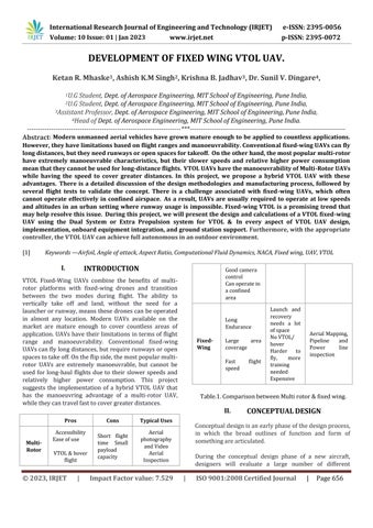
VTOL Fixed-Wing UAVs combine the benefits of multirotor platforms with fixed-wing drones and transition between the two modes during flight. The ability to vertically take off and land, without the need for a launcherorrunway,meansthesedronescanbeoperated in almost any location. Modern UAVs available on the market are mature enough to cover countless areas of application.UAVs have their limitationsintermsof flight range and manoeuvrability. Conventional fixed-wing UAVscanflylongdistances,butrequirerunwaysoropen spacestotakeoff.Ontheflipside,themostpopularmultirotor UAVs are extremely manoeuvrable, but cannot be used for long-haul flights due to their slower speeds and relatively higher power consumption. This project suggests the implementation of a hybrid VTOL UAV that has the manoeuvring advantage of a multi-rotor UAV, whiletheycantravelfasttocovergreaterdistances.
II. CONCEPTUAL DESIGN
Conceptualdesignisanearlyphaseofthedesignprocess, in which the broad outlines of function and form of somethingarearticulated.
During the conceptual design phase of a new aircraft, designers will evaluate a large number of different
concepts, searching for the one that meets the requirementsin the best way.Thismeansthat they need toiterativelycyclethroughsketchingaconcept,analyzeit andevaluateandcompareitsperformances.
ConceptualDesignisastep-by-stepprocess,westartwith mission requirements as per requirement weight estimation is done for the mission. Weight estimation is an iterative process depending upon ‘Geometric Constraints’, ’Airfoil Selection and ‘Performance parameter’ once the configuration is selected, then the empiricalestimationofstabilityandperformanceisdone andbasedonthatpowerplantselectionisdone.
A. Weight Estimation
ConceptualDesignCalculations:
Table.2.WeightEstimation.
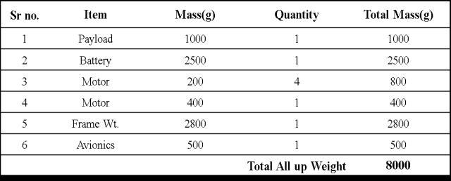
Weight estimation is important because it is basic for mission requirements. Most of the item weights can be decided by doing a market survey, like for payload, battery,avionicsandmotorwhereasforframeweightitis an assumption. After weight estimation, we can move to the next step which is airfoil selection now we know the weight so we need an airfoil which can produce enough weightasawing.
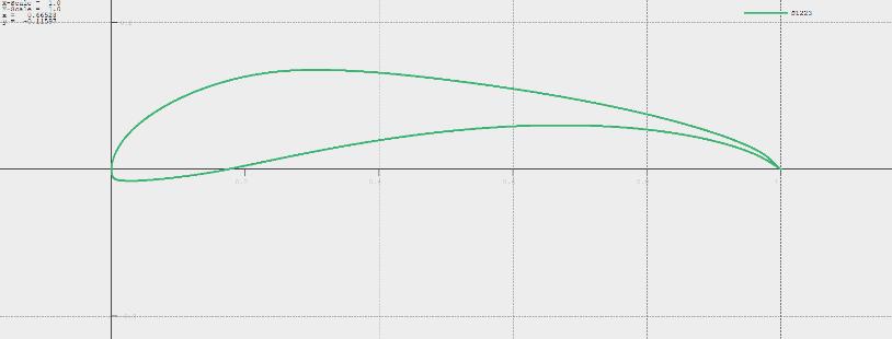
B. Airfoil Selection
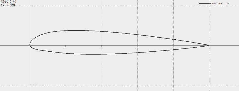
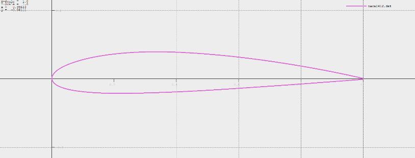
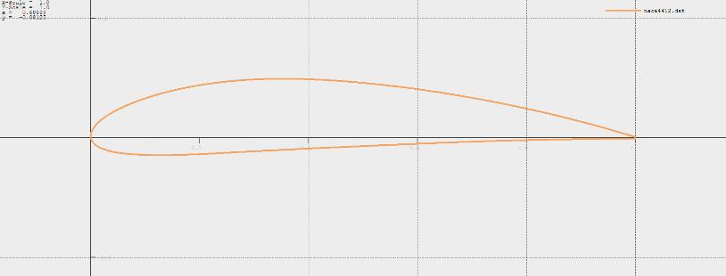
For the selection of airfoil first, we have to decide the cruise velocity after deciding velocity then we calculate the Reynolds number to get airfoil data so for this we decidedonarangeofvelocitywhichis15m/sto30m/s after calculating these velocities we get a range of Reynoldsnumberwhichisshownbelow.
TheReynoldsnumberiscalculatedfrom:
=Thedensityofthefluid
=Thedynamicviscosityofthefluid
=TheKinematicviscosityofthefluid
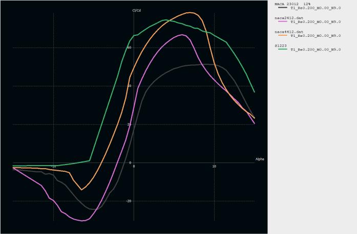
Reynolds Number range at 120 m altitude for velocity 15m/s&30m/sis300,000to600,000. NowaftergettingtherangeofReynoldsnumber,wehave tochoosesomegoodliftgeneratingairfoils. Wehad4optionsfortheairfoil
Where:
v=velocityofthefluid
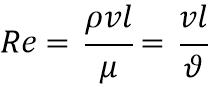
l=Thecharacteristicslength,thechordwidthofanairfoil
All the above airfoils have good performance in the selected range of Reynolds number but comparing them togetherinXFLR-5.
Hence,fromtheabovegraph,wecansaythatNACA4412
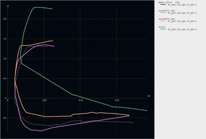
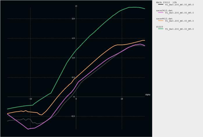
fitstherequirement.
So, we choose NACA 4415 to work on. The main reason forchoosingthisairfoilisthesameliftasNACA4412but morethicknesssoitisbeneficialforsparattachmentdue to more thickness our spar will be greater so it will give morereinforcementandsupport.
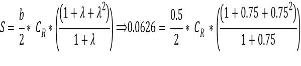
C. Calculations
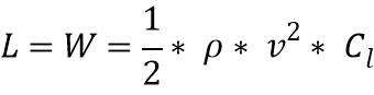
MTOW=8Kg,V=16.66m/s, ,
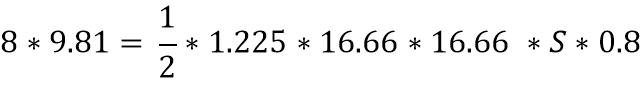
S=0.58
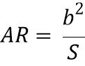
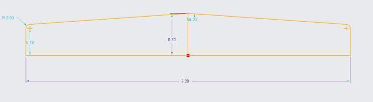
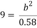
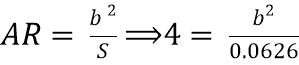
ChoosingAR=9
b=2.28m
c=0.25m
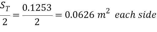
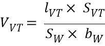
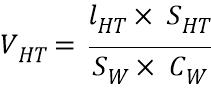
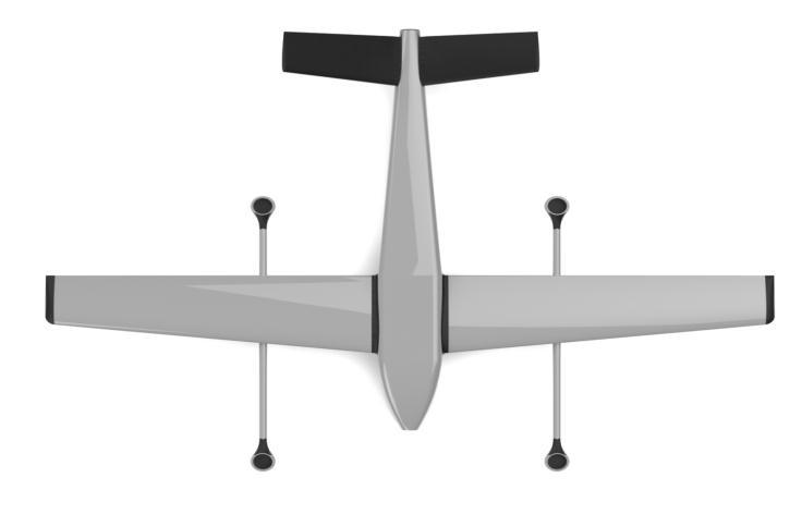
wearetakingaVtailinthisdesignsobecauseofthatwe are adding both the vertical and horizontal tail areas to getdesiredsurfacearea.
ChoosingARfortail=4
b=0.5m
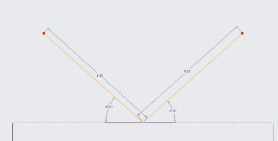
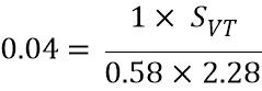
Table.3.
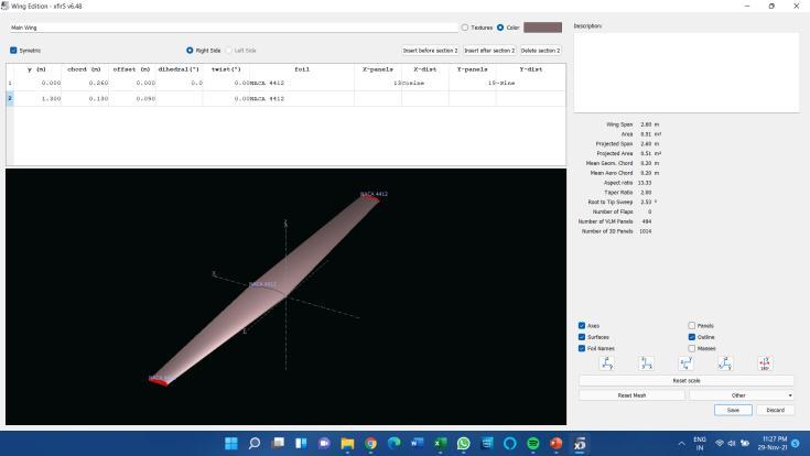
DesigningthewingonXFLR-5togetthecoefficientoflift and coefficient of drag, to know whether the values will be efficientor not.ThevalueofCL wegotfrom XFLR-5is around0.66at2.5AOA.
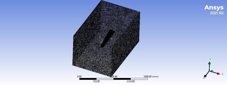
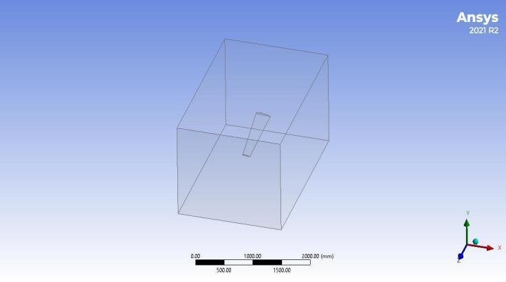
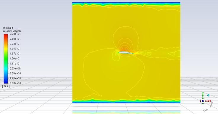
To validate this result, we also did a CFD analysis on Fluent.ForCFDanalysisinfluent,westartwithdesigning the wing and then an enclosure around the wing, the dimensionoftheenclosureis2.5binfrontand5bbehind.
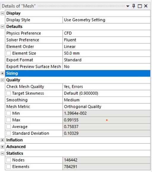
Moving towards meshing, element size of 50 mm. the orthogonal quality around minimum 1.39e-2 and maximum 0.9915. The total element count is around0.78 million.
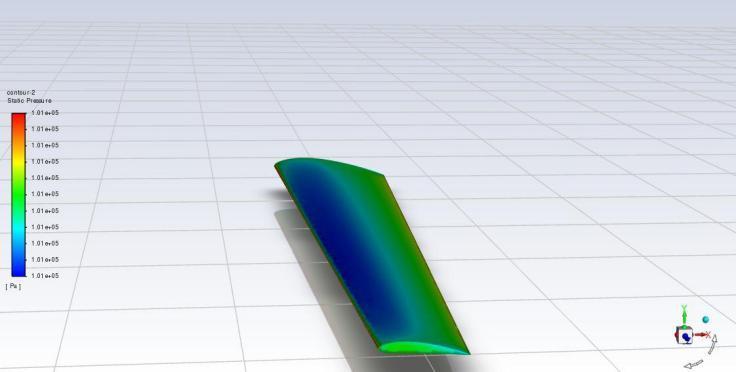
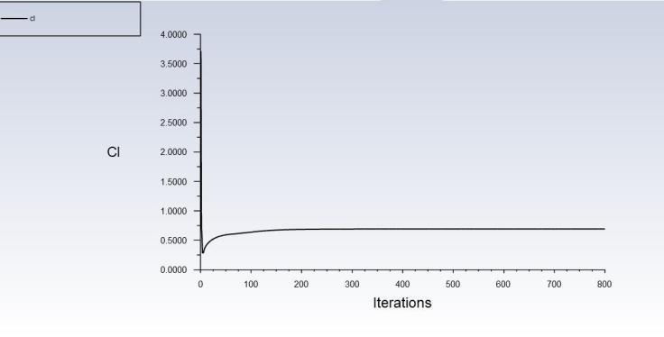
The Numerical setup for simulation was the K-epsilon turbulence model. The velocity was 16.667 m/s and the operating pressure of 101325 Pa. The P-V coupling was selected to be SIMPLE with the second order. The simulation was around for 800 iterations. For results, pressure contour was observed on the wing and velocity contouraroundthewingandcoefficientofliftgraph.
The value of the coefficient of lift we got from CFD analysis was 0.60, which has around a 6% error with respecttotheXFLR-5result.Hence,wecansayourresult isvalidated.
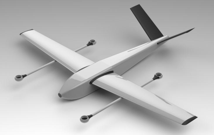
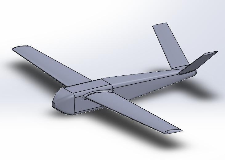
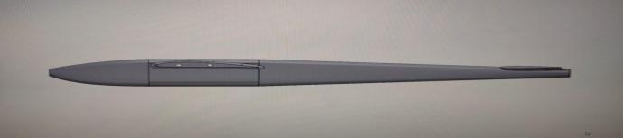
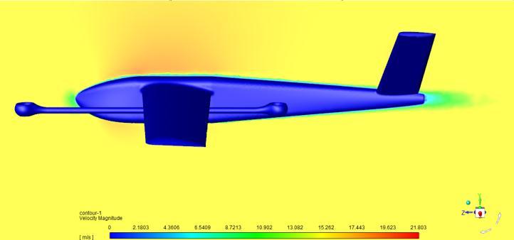
Here,makingthemodelmorestreamlinedandefficientis thegoalandaddingtheboomsforVTOLmotors.Afterthe CADModelling,wemovetowardsCFDanalysis.
Aftertheresultsforthecoefficientofliftarevalidated.We can move towards designing the model on Solidworks software.
Thedomainforthemodelwas5binfront10bbehindthe model and 10b around. After the enclosure is ready, we startwiththemeshingofthewholemodel.Westartwith the surface mesh for the UAV and then the volume mesh of the enclosure domain. The mesh quality for mesh was Min 8.71e-3 Max 0.999. The skewness was contained under0.95,andthegrowthratewas1.2toensuresmooth transition.
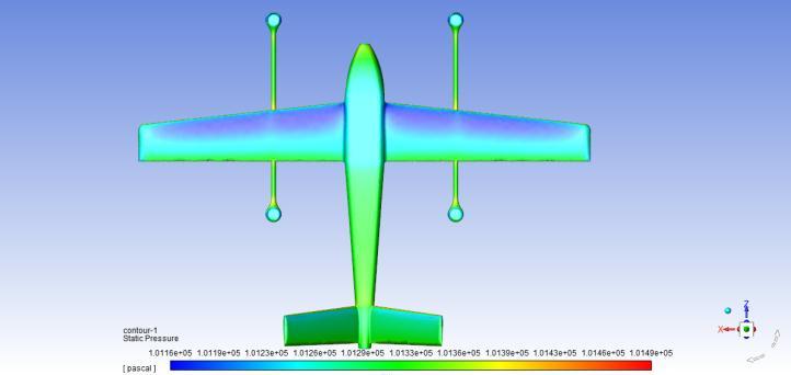
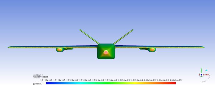
Solversetuponfluent
For results, pressure contour was observed on the UAV andvelocitycontouraroundtheUAVandcoefficientoflift graph.
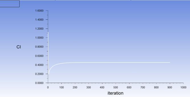
V. CONCLUSION
Here we can conclude that using this methodology, we designed fixed wing VTOL UAV and further analyzing we got appreciative values for coeffient of lift and pressure contour suggesting the methodology was correct and simpletouse.Bymodifyingtheneedsaccordingly,wecan move forward for its prototyping and after a successful flighttestoftheprototypewearegoodtogoforthefinal productmanufacturingprocess.
VI. REFERENCES
[2] Watcharapol saengphet, chalothornT humthae, Conceptual design of fixed wing-vtol UAV for AED transport, SuranareeUniversityofTechnology.
[3] Symon reza, samsul Mahmood, Performance analysis and comparison of high lift airfoil for low-speed
unmannedaerialvehicle,NationalInstituteofTechnology Jamshedpur.
[4] Haowei gu, ximin lyu, zexiang li, shaojie shen, fu zhang Development and experimental verification of a hybrid vertical take-off and landing (VTOL) unmanned aerialvehicle(UAV).
[5] Mayurkumar kevadiya, Hemish A. Vaidya, “2d analysis of NACA 4412 airfoil,” Government College of Engineering,Valsad,Gujarat,India.
[6] D.F.Finger,C.Braun,C.bil,TheImpactofElectric PropulsiononthePerformanceofVTOLUAVs
[7] Maxim Tyan1, Nhu Van Nguyen2, Sangho Kim1, and Jae-Woo Lee1, “Comprehensive preliminary sizing/resizing method for a fixed wing – VTOL electric UAV,”KounkukUniversity.
[8] Yucel OrkutAktas,Ugur Ozdemir, Yasin Dereli, Ahmed Farabi Tarhan , Aykut Cetin , Aslihan Vuruskan , Burak Yuksek , Hande Cengiz , Serkan Basdemir , Mesut Ucar , Murat Genctav , Adil Yukselen , Ibrahim Ozkol , Metin Orhan Kaya , Gokhan Inalhan, “A Low-Cost Prototyping Approach for Design Analysis and Flight TestingoftheTURACVTOLUAV”.
[9] ÖzgürDündar,MesutBilici,TarıkÜnler,“Design andperformanceanalysesofafixedwingbatteryVTOL UAV.
[10] Karkera yathish, siddalingappa pk, sheldon mascarenhas,Chinthandsouza &hitesh bali, “Thedesign anddevelopmentoftransitionalUAVconfiguration.”
[11] Lance W. Traub, “Range and Endurance Estimates for Battery-Powered Aircraft,” Embry-Riddle AeronauticalUniversity,Prescott,Arizona.