DESIGN AND ANALYSIS OF FRAME FOR MOBILE SOLAR POWER STATION
Kesina Sahith Krishna1, Kolluri Madhava Veera Venkata2, Sai Allamsetti Sai Sumanth31Department of Mechanical Engineering, MVGR College of Engineering, Vizianagaram
2Department of Mechanical Engineering, MVGR College of Engineering, Vizianagaram
3Department of Mechanical Engineering, MVGR College of Engineering, Vizianagaram
***
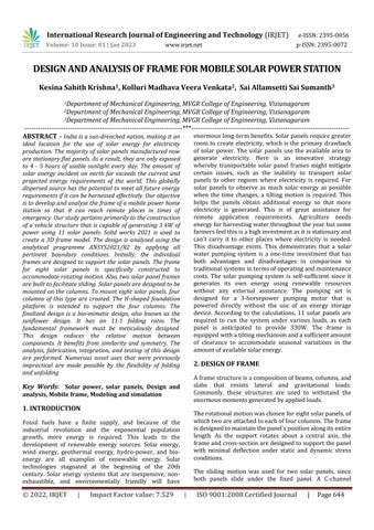
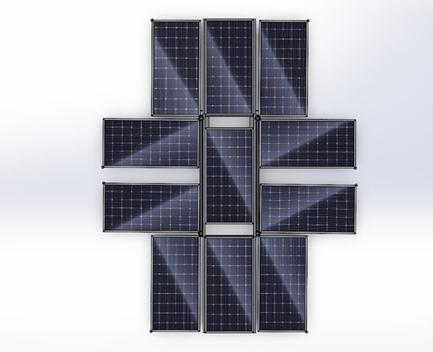
ABSTRACT - India is a sun-drenched nation, making it an ideal location for the use of solar energy for electricity production. The majority of solar panels manufactured now are stationary flat panels. As a result, they are only exposed to 4 - 5 hours of usable sunlight every day. The amount of solar energy incident on earth far exceeds the current and projected energy requirements of the world. This globally dispersed source has the potential to meet all future energy requirements if it can be harnessed effectively. Our objective is to develop and analyse the frame of a mobile power home station so that it can reach remote places in times of emergency. Our study pertains primarily to the construction of a vehicle structure that is capable of generating 3 kW of power using 11 solar panels. Solid works 2021 is used to create a 3D frame model. The design is analysed using the analytical programme ANSYS2021/R2 by applying all pertinent boundary conditions. Initially, the individual frames are designed to support the solar panels. The frame for eight solar panels is specifically constructed to accommodate rotating motion. Also, two solar panel frames are built to facilitate sliding. Solar panels are designed to be mounted on the columns. To mount eight solar panels, four columns of this type are created. The H-shaped foundation platform is intended to support the four columns. The finalized design is a bio-mimetic design, also known as the sunflower design. It has an 11:1 folding ratio. The fundamental framework must be meticulously designed. This design reduces the relative motion between components. It benefits from similarity and symmetry. The analysis, fabrication, integration, and testing of this design are performed. Numerous novel uses that were previously impractical are made possible by the flexibility of folding and unfolding
Key Words: Solar power, solar panels, Design and analysis, Mobile frame, Modeling and simulation

1. INTRODUCTION
Fossil fuels have a finite supply, and because of the industrial revolution and the exponential population growth, more energy is required. This leads to the development of renewable energy sources. Solar energy, wind energy, geothermal energy, hydro-power, and bioenergy are all examples of renewable energy. Solar technologies stagnated at the beginning of the 20th century. Solar energy systems that are inexpensive, nonexhaustible, and environmentally friendly will have
enormouslong-termbenefits.Solarpanelsrequiregreater room to create electricity, whichisthe primary drawback of solar power. The solar panels use the available area to generate electricity. Here is an innovative strategy whereby transportable solar panel frames might mitigate certain issues, such as the inability to transport solar panels to other regions where electricity is required. For solar panels to observe as much solar energy as possible when the time changes, a tilting motion is required. This helps the panels obtain additional energy so that more electricity is generated. This is of great assistance for remote application requirements. Agriculture needs energyforharvestingwaterthroughouttheyearbutsome farmersfeelthisisahighinvestmentasitisstationaryand can't carry it to other places where electricity is needed. This disadvantage exists. This demonstrates that a solar water pumping system is a one-time investment that has both advantages and disadvantages in comparison to traditionalsystemsintermsofoperatingandmaintenance costs. The solar pumping system is self-sufficient since it generates its own energy using renewable resources without any external assistance. The pumping set is designed for a 3-horsepower pumping motor that is powered directly without the use of an energy storage device. According to the calculations, 11 solar panels are required to run the system under various loads, as each panel is anticipated to provide 330W. The frame is equippedwithatiltingmechanismandasufficientamount of clearance to accommodate seasonal variations in the amountofavailablesolarenergy.
2. DESIGN OF FRAME
Aframestructureisacompositionofbeams,columns,and slabs that resists lateral and gravitational loads. Commonly, these structures are used to withstand the enormousmomentsgeneratedbyappliedloads.
Therotationalmotionwaschosenforeightsolarpanels,of whichtwoareattachedtoeachoffourcolumns.Theframe isdesignedtomaintainthepanel'spositionalongitsentire length. As the support rotates about a central axis, the frameandcross-sectionaredesignedtosupportthepanel with minimal deflection under static and dynamic stress conditions.
The sliding motion was used for two solar panels, since both panels slide under the fixed panel. A C-channel
memberisusedasaguidetoretractthepanelinaspecific direction, with square members attached to both sides of the panel that slide into the C-groove. The cross section and thickness of the channel are dictated by the pull-out weightoftheoverhangofthepanel.
2.1 MATERIALS SELECTION
Thematerialischosenbasedonitsadaptabilitytoseveral commonproductionproceduresthatmightbefoundinan educational institute, as it must be fabricated there. Generally, alloy steels and plain carbon steels were preferred.MildsteelEN3Bischosenbasedonavailability.
OverallH-basedimensions:94.49*49.24inches
Rectanglesection:4*2inches
The aforementioned dimensions are fixed based on numerousiterations.
2.3 CAD MODEL
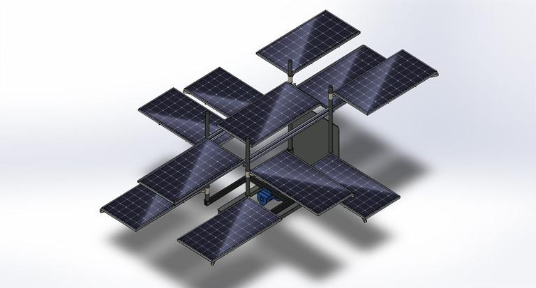
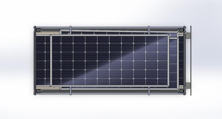
Theretractedviewoftheentireassemblyisshownbelow (Figure2.1;2.2)
2.2 BASIC PARAMETERS
Each component and final assembly parameter is chosen in consideration of the characteristics that must be kept optimal in order to accommodate all components and achieve minimum space. Parameters for components are statedbelow.
Solarpanel:77*39inches
PrimaryPoleDiameter:2.5*0.12inches
PrimaryPoleheight:78.74inches
SecondaryPoleDiameter:3.49*0.3inches
SquareDiagonallength:87.5inches
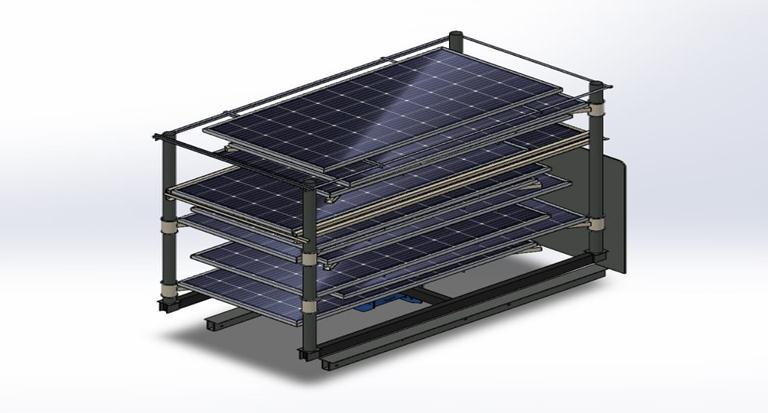
Thedeployedviewofthe entireassemblyisshownbelow (Figure2.3;2.4)
3. ANALYSIS SOFTWARE
To simplify complex and laborious problems, the model canbedefinedasfiniteelementsandthenitsstrengthcan be examined. There are numerous analysis tools, such as HYPERMESH, NASTRAN, and ANSYS. We chose ANSYS as ouranalysistool.
3.1 ANSYS METHODOLOGY
The frame must be inspected for stress and strain generated by static forces, as well as bending moments causedbytheweightofthesolarpanelandtheself-weight offramepartsactingonthesupportpoint.Theseanalyses will indicate the maximum permissible stress and responses at joints along the members of the frame, as wellasprovideinsightintotheweakestcomponentofthe design due to its geometric shape, thereby identifying those portions of the frame with the most stress and deformation.
Thiswillalsoaidindeterminingtheframe'sstiffnesswhile forces are being applied. Using ANSYS workbench, we performed a finite element analysis on the frame of our solar panel. The analysis was performed on several componentsofthesolarpanel suchas Column,base and frameofthesolarpanel.
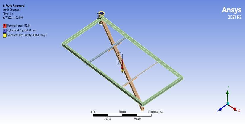
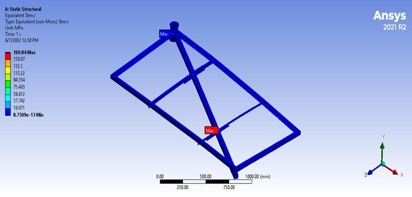
3.2 Boundary conditions of frame with rotary motion
Static structural analysis of a frame with rotary motion is performed by applying the boundary conditions illustratedinfigure1.5.2(a),whichare:
1. A cylindrical support of 0 mm is provided at the cylindricalportionoftheframe.
2. A remote load of 150N is applied through the centre of gravitytotheentireframe.
3.Thestandardgravityoftheearthisprovided
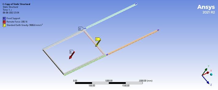
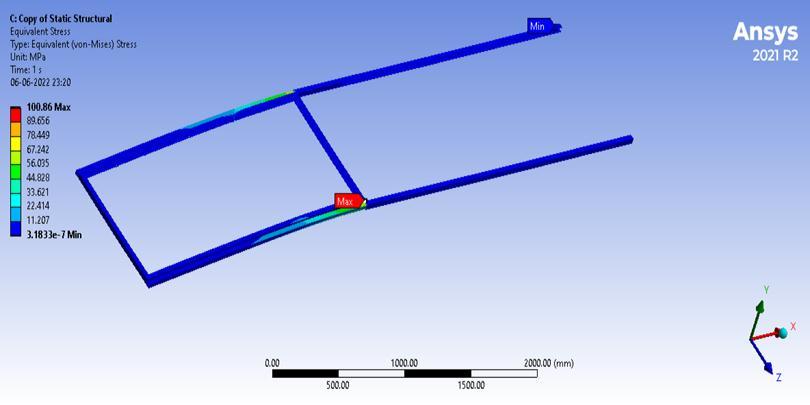
3.3 Boundary CONDITIONS OF frame with sliding motion
Staticstructuralanalysisforaframewithslidingmotionis done by applying boundary conditions as shown in figure 1.5.3(a),whichare
1.Fixedsupportsaregivenatfourendfacesoftheframe.
2. A remote load of 200N is applied to the overall frame, actingthroughthecenterofgravity.
3.Thestandardearthgravityisgiven.
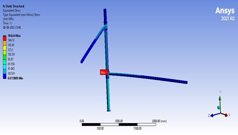
3.4 Boundary conditions for column
Staticstructuralanalysisforacolumnisdonebyapplying boundaryconditionsasshowninfigure1.5.4(a),whichare
1.Fixedsupportsaregivenatbottomofthecolumn.
2. A remote load of 250N is applied to the column's two diagonalmembersthatactthroughthecenterofgravity.
3. Thestandardearthgravityisgiven.
Static structural analysis for a base platform is done by applying boundary conditionsasshown in figure 1.5.5(a), whichare
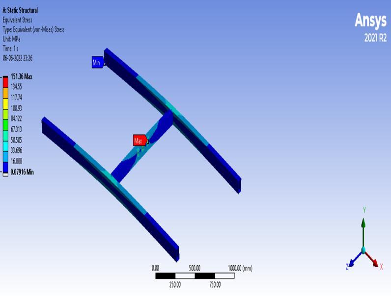
1. Cylindrical support of 0 mm is given at four corners of thebaseplatform.
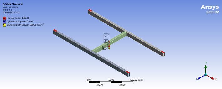
2.Aremoteloadof4500Nisappliedtothebasethatacts throughthecentreofgravity.
3.Thestandardearthgravityisgiven.
Themaximumstressobtainedontherectangularframeis shown in figure1.6.2(a) for sliding motion when a load of 200Nisappliedis100.86MPa
4.
The maximum stress obtained is shown in figure1.6.1(a) ontherectangularframeforrotarymotionwhenaloadof 150Nisappliedis169.84MPa.
The maximum stress obtained on the base platform is showninfigure1.6.3(a)whenaloadof4500Nisappliedis 151.36MPa
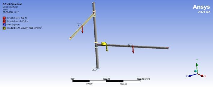
The maximum stress obtained on the column is shown in figure1.6.4(a) when a load of 250N is applied is 184.64MPa.
observed as 1.2 and above from results which is consideredsafe.
5. Parameters such as overall length of the frame is 106.69”inch,themaximumwidthoftheFrameis44”inch, MaximumheightoftheFrameis106.66”inchand Weight oftheframeis550kgs.
6. ACKNOWLEDGEMENT
FordesigningtheAll-terrainVehicle,wealsoliketothank Team Invincible Racing. We also convey our heartfelt appreciation and gratitude to Dr. M.K.Naidu for allowing ustoworkonthisproject.Weare extremelyappreciative ofhisassistanceandguidanceinthisproject.
7. REFERENCES
[1] Dan Chaimovski, Tel Aviv, Reuven Marko, Netanya, Yuval Shachar, Herzliya Pituach (2015) “Portable folding solar panels” PublicationChaimovskietal.
[2] BrandonKretchmer,RyanMonahan,AldoGarcia,Eric Garner, Brian Sims, Nnadozie Njoku, Michael Lahey, Nicolau Monteiro, “Solar Powered Electric Vehicle” College ofEngineering andSciences PurdueUniversityNorthwest April26,2017
[3] S. Yogesh, M. Yoga Lakshmi, M. Abhishek, R. Ari Prasath, G. Madhusudanan (2021) “Origami based folding techniques for solar panel applications” International JournalofElectricalEngineeringandTechnology(IJEET)
[4] Binyamin Jasim, Pooya Taheri, Langara College, Vancouver, Simon Fraser University (2018) “An OrigamiBased Portable Solar Panel System” IEEE 9th Annual Information Technology, Electronics and Mobile CommunicationConference(IEMCON)
[5] K.S. Madhuetal., “Intelligent Two Axis Solar Tracking System with Mechanical Application” International Journal of Scientific & Engineering Research Volume 3, Issue 9, September-20121ISSN:2229-5518
5. CONCLUSION
1. The Frame for rotary motion, sliding motion, column andbaseplatformweredesignedandanalysed.
2. The material selected was Mild Steel of EN3B grade withayieldstrengthof240MPa.
3. The static structural analysis was performed on differentframessuchasframeforrotarymotion,framefor slidingmotion,columnsandbaseplatform.
4. The design targets were reached by meticulous detailing in every aspect. The factor of safety was
[6] S.Shafie;M.Z.A.AbKadir;N.Azis;M.A.M.Radzi;W. H. W. Zuha; M. A. Mustafa “High Efficiency Portable Solar Generator utilizing Optimum Solar Panel Orientation” (2018)
[7] Universiti Teknologi MARA, Shah Alam Selangor
“Solar GO: Backpack Solar Powered Generator” Conference: Invention,Innovation&DesignExposition2016
[8] Prof. A. R. Suryawanshi et al., Solar Based Variable Frequency Drive International Research Journal of Engineering and Technology (IRJET) ISSN: 2395 -0056 Volume:03Issue:03,March2016
[9] Hugh Rudnick's “Impact of Natural Disasters on Electricity Supply” May 2011 IEEE Power and Energy Magazine.
[10] Svetlana Makasheva and Pavel Pinchukov, “Autonomous power supply technology in terms of natural and technogenic disasters” MATEC Web of Conferences 265:07002,January2019.
[11] H-method Vs. P-Methodhttps://deust.wordpress.com/2014/11/30/h-method-pmethod.