International Research Journal of Engineering and Technology (IRJET) e-ISSN: 2395-0056

Volume: 10 Issue: 01 | Jan 2023 www.irjet.net p-ISSN: 2395-0072
International Research Journal of Engineering and Technology (IRJET) e-ISSN: 2395-0056
Volume: 10 Issue: 01 | Jan 2023 www.irjet.net p-ISSN: 2395-0072
1M.Tech. Student, Dr. Ambedkar Institute of Technology, Bangalore, India. 2 Associate Professor & Head, Dept. of Mechanical Engineering, Dr Ambedkar Institute of Technology Bangalore, India ***
Abstract - Air foil thrust bearing (AFTB) or gas foil thrust bearing(GFTB) works on the principle of hydrodynamic lubrication, load supported here is the axial load or thrust load. These are independent from the conventional bearings because there will be no surface contacts. And in the hydrodynamic lubrication there will be no contact of bearing parts and no damage respectfully. In our experimental procedure the major advantage is the bearing diameter which is 224 mm which is large when compared to other experimental procedure carried out in AFTB. We have studied on the different parameters of the bearing such as foil thickness, sector angle, operating speed and how the wedge film formation takes place in bearing and how the load capacity and stiffness of the bearing can be increased. We have conducted the experiment on copper foil of thickness 0.3, 0.4, 0.5 mm respectively. The operating speed of the AFTB test rig is between 10000 - 20000 rpm. We have carried out the experiment in the two phases that is in first case we have done in the static condition and in the second phase we have done in the dynamic condition. The better possible study has been done to determine the load and stiffness of the bearing.
Key Words: AFTB, load, stiffness, operating speed
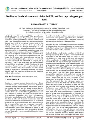
Bearing is a machine element that restricts the relative motiontoonlythedesiredmotion,andlowersthefriction andwearbetweenthemovingparts.Thedifferenttypesof the bearing are plain bearing, rolling element bearing, Jewel bearing, fluid bearing (air), and magnetic bearing. AndtheAFTB(AirFoilThrustBearing)AlsoComesunder the Category Air bearing and works on the principle of Hydrodynamic lubrication. The term hydrodynamic lubricationcanalsobecoinedasfluidfilmlubricationand the fluid is called air. These are independent from the conventional bearings because there will be no surface contacts. And in the hydrodynamic lubrication there will be no contact of the parts and no damage respectfully. TherewillbestatorandtherotorinAFTBandthefoilsare attached to the stator. When the power is applied to the rotor, it starts rotating and is set for different rotating speeds.Thedetailedhydrodynamicfilmlubricationisseen infigure2.
It used in the turbo machinery applications, aerospace applications, rotor dynamic applications, food industries, turbo chargers, turbo expanders, coordinate measuring machine,turbocompressors,textilespindles.
Airgapinbearingsandtherewillbenosurfacecontactas in the case of the conventional bearings. So mainly in this kind of the bearings there will be no vibrations, damping, andothervibrationrelatedproblems
Iordanoff (1) did a study on the compliant air foil thrust bearing respectively. Here he gave a conclusion that the experimental load calculation and the analytical load calculationAsweknowintheairfoilthrustbearingthere will bebasedonthetheorybothsatisfies.Inthisstudy he operated the test rig at 50000 rpm respectively with bearinginnerdiameter40mm,outerdiameter80mm.Also inthisthereisbumpfoilandtopfoil,andwiththenominal filmthicknessrespectfullyof1.9micrometerto2.5micro metertheloadcanbeobserved,finallyloadisweakwhen both the rotor and bearing pad touch each other and the top and bump foil touch each other. Bauman (2) conducted the experiment in the air foil test bearing rig and listed the important parameters such as load, speed, torque, temperature but the main parameter is the temperature is the which is almost 650 degree Celsius. Here he explained that the vibrations caused are preliminary due to the shaft and not the foil bearing. Finally the main thing he explained is that the load increases due to the passage of the air film, also we can find that the exact load is the difference of applied load and the load generated between the foil and runner and fixed plate Brain dykas, Joseph Prahl (3) gave a detailed analysis of heat generation takes places in foil thrust air bearing. As we know in this type of the bearing when rotating at the higher speeds between the air film pressures causes heat on the foil surface we have to counter this type of the problems because it can cause shearonthesurfacerespectfully.DongJinPark,ChangHo Kim (4) have analytical conducted the experiment by keepingtherunnerintilted planeinonecaseandparallel in other case. From all the above cases bearing torque, stiffness, load has been observed. Also the main thing observediswhenthebearingpadistiltedthemaximumof the load and torques is increased. Also the main thing is theeccentricratioincreasesisdirectlyproportionaltothe
International Research Journal of Engineering and Technology (IRJET) e-ISSN: 2395-0056
Volume: 10 Issue: 01 | Jan 2023 www.irjet.net p-ISSN: 2395-0072
loadincreased.SomayaK(5)Inaddition,itwasfoundthat inserting a metal plate between the top foil and the viscous elastic support at the landing region could improvetheloadcapacity,andthattheloadcapacityofthe proposedfoilbearingreached160Nat20000r/min.Here he conducted series of experiment both experimentally andanalyticallyinonecriterionhedidsandwitchtype of experiment with foil, adhesive tape, silicon rubber and in the second case he placed the metal in between the tape and the silicon rubber where load increased significantly. Yonk- Bok lee, Tae-hokim (6)conductedthe experiments byvaryingthethrustloadofbearing.Inthisexperimental results compared with random stiffness of mathematical modelgavegoodoutputofthisbearing.Asweknowifthe rotating speeds of the runner increase air film thickness which corresponds to increase in the load, also in turn correspondstoincreaseinbearingnumber.Donghyunlee, Daejong kim (7) conducted the design or synthesis and prediction performance of hybrid air foil thrust bearings respectively.Intheir design theyhavecreatedtheslots in foiltoaccommodateorifice.Alsotheyhavedonethestatic and dynamic characteristics at different place of orifice in the plate to see pressure film distribution. Tae ho Kim, Yong-bok lee, Tae Young Kim (8) they did a study on the increase of Performance of an Oil-Free Turbo Blower Focusing on Load increases of Gas Foil Thrust Bearings. Here with the increase of the tilting angles of the bearing pad they observed that the load carrying capacity of the bearingwasdecreased.RobertJBruckner(9)conducteda studyontheenhancementofsimplestofthegasfoilthrust bearings and he observed the important parameters such as frictional torque, speed, temperature and load. In this with the same foil he conducted the experimental test results with varying rpm he didn’t find that load increasing linearly. Ravi Kumar R N, Rathanraj K J(10) heretheretheyhavemadethesectorfoilswheretheinner edge and outer edge height decreases and the other is cascading the foils and here they have observed that the load carrying capacity is increased respectfully because thenoofthewedgesCreatedaremore.TaehoKim,Moon Sung Park, Jong Sung Lee, Young Min Kim (11) here they did excitation process by a shaker to induce constant vibrations also they found the dynamic characteristics of thebearing.Thatistheyareincreasingfrequencywhichin turnincreasesthedynamicload.Alsothebearingdamping coefficient, stiffness increases by the applied frequency respectively.Choonghyunkim,Jisupark(12)designedthe rigoffoilthrustbearingintheverticalmannerasweseen in the many cases it is horizontal manner, by this kind of arrangement of the rig he noticed that the higher amount offriction,frictionaltorquewasnoticed.Basedonvertical manner of arrangement of rig the air flow between the bearing pad and the thrust pad was seen very well at the higher speed. Tae Ho Kim, Moon sung Park, Tae Won Lee(13) conducted the experiment in the bearing test rig by increasing the ramp height with certain (mm) of increments, also by varying the speed so on by doing this
the load was noted. By doing the above experimental results they found that with decreasing ramp height the loadincreases. The two different variablestudiedis ramp height, inclination angle. And other different variable discussed here are the drag torque, stiffness which are alsointerlinkable.SupreethS(14)itwasobservedwithin the increases no of foils, the greater the load speed with the less air gap respectfully. As we know with the lesser theairgapmoreamountoftheloadcanbewithstandand also the main point is inner and the outer edge of the foil are parallel with respect to the back plate. Also it was notedthatthefoilwithlessthicknesscanwithstandmore amountoftheload.
Fig -1: AirFoilBearings
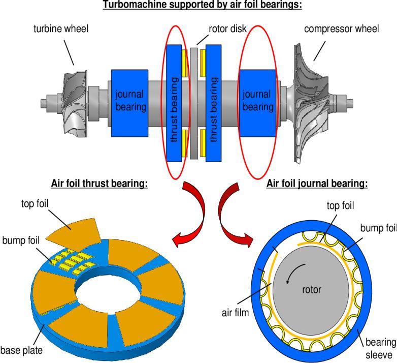
Fig -2: PrincipleofFoilThrustBearing
International Research Journal of Engineering and Technology (IRJET) e-ISSN: 2395-0056
Volume: 10 Issue: 01 | Jan 2023 www.irjet.net p-ISSN: 2395-0072
The conduction of the experiment in the AFTB test rig is done using copper foil with thickness of 0.3, 0.4 mm and also by varying the sector angle by 45,60,75,90 degrees. The entire experimentation process is carried out in two stages. In first stage doing the experiment in the dynamic condition and in second stage is static condition in both thestagesload,stiffnessaremeasured.
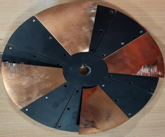
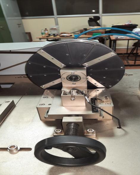
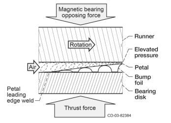
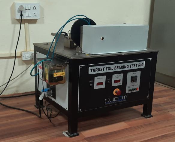
First we are starting with the 0.4mm foil respectively. As we already know there are 4 different sector angles varying from 45-90 degree in increments of 15 degree respectively. We are conducting the experiment for each and every sector angle and noting down the load and stiffness in both static and dynamic condition. And again we are starting with the 0.3 mm foil and doing the same experimentationprocedureaswedidinthe0.4mm.Inthe courseofdoingtheexperimentwearealsoincreasingthe speed of the rig in the increments of 2000 rpm and it can reach up to speed of 20000 rpm which is maximum and aboveitcan’tbereached.Thespeedoftherigisincreased from the beginning till the maximum speed for every sector angle varying from 45,60,75,90 degrees of the corresponding thickness of 0.3,04 mm foil respectively. Thereisaknobtoincreasethespeedandadjacenttothat display is given to note down the speed and adjacent to that load measured display also there where we can take the different readings while performing the experimentation. As in our experiment we are constantly removingthecopperfoilsfromthe bearing padandagain insertingtoitforthevarioussectoranglesitisdonewith help of threads and fasteners for easy removal and performing the experiment. The bearing pad should be almost made exactly parallel to the surface of the rotor which means the outer and inner edge of the free end of thefoilshouldbemadeparalleltotherotorsurfacesothat very good hydrodynamic film lubrication takes place and the good amount of the load can be with stand. In the course of doing the entire experimentation circulation tank should be on because of the cooling down of the spindle is necessary as more amount of heat generation takes place. While performing the experimentation the bearing pad must be fixed accurately otherwise the rotor which rotates at higher speed may cause damage to the person who’s performing the experiment these are safety precautions and measure should be taken. Also while performing the experimentation once used foil cannot be used as the stiffness in the foil will not be retained and good precision and accurate results would not be obtained. The copper foil after being performed experiment in AFTB test rig is shown in figure 4 and7. AlsowecanseetherigofAFTBinfigure3.
International Research Journal of Engineering and Technology (IRJET) e-ISSN: 2395-0056
Volume: 10 Issue: 01 | Jan 2023 www.irjet.net p-ISSN: 2395-0072
ourexperimentalvalidationwemayobservethatiseasily deflectedandhavingthelessstiffness.
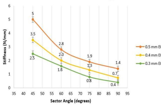
The maximum stiffness value obtained is 5(N/mm), the abovecriteriadiscussedalsoholdsgoodinthecaseof0.3, 0.4mmrespectively.Inthecaseof0.3,0.4mmthestiffness valueobtainedis3.5(N/mm)and2.5(N/mm).
W=load(N)
L=lengthofthefoil(mm)
E=modulusofelasticity(N/mm^2)
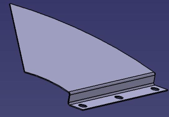
Fig -6: 45Degreecopperfoil
I=momentofinertia(Kg.m^2)
=deflection(mm)
From the above equation it may be noted that the as length on the foil goes on increasing deflection delta goes onincreasesbythisanalogyonecanunderstandthatwhy the stiffness in 0.5 mm copper foil is greater than comparedtootherfoils.
Fig -7: StaticstiffnessofAFTBwith4copperfoils
Theresultshavefoundoutintwocriteriabasedonthe experimentation procedure
Nowletusdiscusstheresultsofstaticconditions.Herewe are discussing the different parameters in the AFTB test rig by not increasing the speed of the rotor, mean to say thatinstandstillcondition.Aswealreadyknowthatbythe basiccommonsenseandelementarylevelsciencethatthe element with the higher thickness will be stiffer and this result may also be observed from the graph by plotting graph of stiffness (N/mm) versus various sectors angles (degrees) for the various thicknesses of the copper foils. From the above figure 7 we may notice that even though stiffness is higher in 0.5 mm it is particularly observed in the sector angle of 45 degree and it is much higher than 60,75,90 degree. As earlier explained in the dynamic conditionin0.5mmfoilthicknessofsectorangle60,75,90 circumferentialareasorfoilareaismoreandaccordingto
We may observe from the above figure 8, 9 that for the thickness of 0.3, 0.4mm of copper foil a graph of load versus the operating or the running speed were plotted and different parameters were measured. We have conductedtheexperimentsforallthethreethicknessesof foilwhichare0.3,0.4and0.5mm.
International Research Journal of Engineering and Technology (IRJET) e-ISSN: 2395-0056
Volume: 10 Issue: 01 | Jan 2023 www.irjet.net p-ISSN: 2395-0072
But we observed that the foil thickness of 0.5 mm supposed to have very high stiffer and rubbing occurs between the rotor and copper foil which results in the bearingfailure.Itmaybeobservedthatoneofthereasons behind the failure is the operating speed which needs to behigherthanourspeedthatis20000rpm.
circumferentialorsectorareaisoffoilislarge,wedgefilm formation is not possible up to the greater extent and neither good load holding capacity may be observed. The above cited reason for the 75, 90 degree sector angle of foil holdsreasonablywell becausefor both0.3,0.4mm of copper foil 45, 60 degree angle the load holding capacity upto25Newtonthatisequal2.5kg.
AfterperformingtheseriesoftheexperimentinAFTBtest rig the above following graphs were obtained from the experimental data obtained from the rig. We conducted theexperimentinthetwowaysoneisinthedynamicand other is in static condition. We plotted the graph of load versus speed (rpm) for the different thickness of the copper foils. And the thicknesses are 0.3, 0.4mm respectively. We came to know about the different parameters such as stiffness, load, speed, and thickness andsectoranglehowalltheseparametersarecorrelated.
F=load(N)
K=Stiffness(N/mm)
δ=Deflection(mm)
Because if the speed is very high say supposed to be greater than 20000rpm or still very high the foil may deflect easily.Alsowe must notethat for thisthickness of 0.5mmoffoilwehavedoneforvarioussectoranglesthat is 45,60,75,90 degrees but no improvements or satisfied result are not observed. For the foil of thickness 0.5 mm speed may not only be the valid reason it might depends onthematerialorthefoilgeometry.Andbasicallywhywe are stressing on the operating parameter because based on that hydrodynamic lubrication or wedge formation takes place and it may result load withstanding or it may notbehigherstiffer.
Now let us investigate the parameters of 0.3mm, 0.4mm foiloftheAFTBtestrigrespectively.Wemayseethatfrom theaboveplottedgraphforvarioussectorsanglesaplotof loadversus rpmisplotted. Alsoitisclearlyindicatedthat the load holding capacity of the foil with sector angle 45, 60degreeshaveshownthebetterresultscomparedtothe foil of 75, 90 degree respectively. The above load holding capacity of foil with sector angle 45, 60 degree is true in both the cases that are 0.3, 0.4 mm copper foil which can be observed from the above plotted graphs. The main reasonsbehindthefoilsofsectorangle75,90degreesare not showing good load holding capacity because they are having the larger circumferential area can be easily deflected, in other words the foils touches the rotor as soon as the rotor achieves the desirable speed. Even though according to our experimentation process the
From the above equation it may be known that stiffness (K)isinverselyproportionaltothedelta(δ)meansasthe stiffness increases the deflection delta (δ) decreases. Also coming to discuss another parameter that is the load (F) whichisdirectlyproportionaltothestiffnessmeansasthe loadincreasesstiffnessalsoincreases.
After conducting the series of experiments in the AFTB test rig different parameters were study and observed. The parameters are thickness of the foil, sector angle, rampheightandfinallyoperatingspeed.Themainthingin ourexperimentationprocedureandtheconductionofour experiment is that we have done the experiment in two criteria that is first is in the dynamic condition and the second in the static condition. In the static condition we have observed that stiffness parameter is one of the main parametric studies and in dynamic condition load is most discussed parameter. In both criteria parameters were observed for the different thickness of the foils. Also sector angle 45, 60 degree has been shown promising developments. In case of stiffness parameter measured in the static condition 0.5mm copper foil shown good stiffness but it does not shown better load holding capacity in the dynamic condition, but finally if the operating parameter of the rig is greater we can ensure that 0.5mm copper foil can also hold better load holding capacity. Finally in our test rig the bearing diameters are largercomparedtootherresearchworkdoneontheAFTB
2022, IRJET | Impact Factor value: 7.529 | ISO 9001:2008 Certified Journal | Page18
International Research Journal of Engineering and Technology (IRJET) e-ISSN: 2395-0056 Volume: 10 Issue: 01 | Jan 2023 www.irjet.net p-ISSN: 2395-0072
or GFTB so by increasing operating speed the bearing mightshowgoodloadholdingcapacity.
1. Iordanoff I Maximum Load Capacity Profiles for Gas Thrust Bearings Working Under High Compressibility Number Conditions. ASME J Tribology120:571–6,1999.
2. Bauman S, Oil-Free Thrust Foil Bearing Facility Design,Calibration,andOperationNASA/TM2005213568,2005.
3. Dykas B, Prahl J, Dellarcorte C, Bruckner R. Thermal Management Phenomena In Foil Gas Thrust Bearings. ASME Paper No GT2006- 91268, 2006.
4. Park D Theoretical Considerations Of Static And DynamicCharacteristicsOf AirFoilThrustBearing With Tilt And Slip Flow. Tribology International, 41(4),Pp.282-295,2007.
5. K Somaya, S Yoshimoto, and M Miyatake Load capacity of aerodynamic foil thrust bearings supported by viscous elastic material. Tokyo UniversityofScience,Chiyoda-ku,andTokyo,Proc. I Mech E Vol. 223 Part J: J. Engineering Tribology Japan,2008.
6. Yong-Bok Lee, Tae Young Kim, Chang Ho Kim & Tae Ho Kim Thrust Bump air Foil Bearings with Variable Axial Load Theoretical Predictions and Experiments, Tribology Transactions, 54:6,902910,2011.
7. LeeD,KimDDesignandPerformancePredictionof Hybrid Air Foil Thrust Bearings, Journal of Engineering for Gas Turbines and Power, 133(4), P.042501,2011.
8. Tae Ho Kim, Yong-Bok Lee, Tae Young Kim Rotor dynamicPerformanceofan Oil-FreeTurboBlower Focusing on Load Capacity of Gas Foil Thrust BearingsASMEVol.134,2012.
9. Robert J Bruckner Performance of Simple Gas Foil Thrust Bearings in Air NASA/TM-2012-217262, 2012.
10. R.N Ravi Kumar, Rathanraj K J, V Arun Kumar, Comparative Experimental Analysis of Load Carrying Capability of Air Foil Thrust Bearing for Different Configuration Of foil Assembly Procedia Technology1096–1105,2016.
11. Tae Ho Kim, Moon Sung Park, Jongsung Lee, Identification of Dynamic Characteristics of Gas
Foil Thrust Bearings Using Base Excitation Proceedings of ASME Turbo Expo Turbo machinery Technical Conference and Exposition GT2016.
12. Choong Hyun Kim and Jisu Park Testing of Load Capacity of a Foil Thrust Bearing Park Center for Bionics, Bionics Research Institute, Korea Institute of Science and Technology Tribology lubrication Vol.34,No.6,December,2018.
13. TaeHoKim,MoonsungPark,TaeWonLee“Design Optimization of Gas Foil Thrust Bearings for Maximum Load Capacity” ASME Vol. 139 May 2017.
14. S.Supreeth, N.Ravikumar, T.N.Raju & K Dharshan Foil Stiffness Optimization of Gas Lubricated Thrust Foil Bearing In Enhancing Load Carrying CapabilityMaterialsTodayvolume52part3,2022.
15. Supreeth Shivkumar, Thippiah Nagaraju, R.N Ravi KumarA review on performancecharacteristics of an air foil thrust bearing Japanese society of TribologistsVol.17,no4pg276-2822022.
2022, IRJET | Impact Factor value: 7.529 | ISO 9001:2008 Certified Journal |