
International Research Journal of Engineering and Technology (IRJET) e-ISSN: 2395-0056
Volume: 13 Issue: 04 | Apr 2026 www.irjet.net p-ISSN: 2395-0072

International Research Journal of Engineering and Technology (IRJET) e-ISSN: 2395-0056
Volume: 13 Issue: 04 | Apr 2026 www.irjet.net p-ISSN: 2395-0072
Dr. K. Periyarselvam1, Jaya Kumar A B2, Karthikeyan M3, Krishna Kumar V4
1Associate Professor, Department of ECE, 2,3,4 UG Scholar, Department of ECE, GRT Institute of Engineering and Technology, Tiruttani, Tamil Nadu, India
Abstract - Ahigh-availabilitythree-tierarchitecturebuiltusing GoogleKubernetesEngine(GKE)forscalablecloudapplications.
The architecture is organized into three main layers: frontend, backend, and database, which improves system structure, flexibility, and efficient use of resources. To support real-time interaction, WebSockets are used for continuous communication between clients and servers. Kubernetes enhances system stability by managing load distribution, handling failures, and automatically adjusting resources through the Horizontal Pod Autoscaler (HPA). This ensures stable performance even when user demand increases or decreases. An automated CI/CD pipeline is used for faster and more reliable deployment. In addition, monitoring tools such as Prometheus and Grafana are used to observe system behavior and resource usage continuously. The proposed system can handle changing workloads efficiently with very low downtime, making it a strong solution for modern distributed cloud environments.
Key Words: Kubernetes, GKE, High Availability, Docker, CI/CD, Prometheus, Grafana
In modern cloud applications, handling a large number of users while keeping the system always available is a major challenge. Many older system designs cannot manage sudden changesinworkload,whichcanresultinslowperformanceor even system failure during high traffic. To solve this issue, developers use structured design methods like the three-tier architecture.Inthisapproach,thesystemisdividedintothree parts:frontend, backend,anddatabase. This separation helps inbetterorganizationandmakesthesystemeasiertoupdate, scale,andmanage.
Each layer has its own responsibility, which makes development simpler and more efficient. With the growth of cloud technology, tools such as containerization and orchestration have become very important. Docker helps applications run the same way in different environments,
whileKubernetesmanagessystemoperationslikedistributing traffic,handlingfailures,andscalingresourcesautomatically.
Automation is another important part of modern systems. CI/CD pipelines are used to automatically build, test, and deploy applications, reducing manual work and increasing reliability. Monitoring tools like Prometheus and Grafana provide real-time information about system performance, helpingdevelopersquicklyidentifyandfixissues.
In this project, a highly available three-tier architecture is implemented using Google Kubernetes Engine (GKE). The system combines auto-scaling, automated deployment, and continuous monitoring to handle changing workloads effectively and maintain stable performance. By using cloudbased technologies, the system improves resource usage, scalability,andoverallefficiency.
Themainobjective ofthis projectistodesignand implement a highly available three-tier architecture using Google Kubernetes Engine (GKE). The system is divided into frontend, backend, and database layers to improve resource utilization, scalability, and overall system performance. Another key objective is to use Kubernetes features such as automatic scaling and loadbalancing to handle varying levels of user traffic without affecting performance. This ensures that the system remains stable and responsive even during highdemand.
The project also aims to automate the application build and deployment process using a CI/CD pipeline. This reduces manual effort and helps deliver faster and more reliable updates. In addition, monitoring tools are integrated to continuously track system performance, resource usage, and overallhealth.Thisprovidesbettervisibilityandallowsquick identification of issues. It also focuses on improving fault tolerance, ensuring that services remain active even if some components fail. Another objective is to optimize resource usage to reduce operational costs in cloud environments.
International Research Journal of Engineering and Technology (IRJET) e-ISSN: 2395-0056
Volume: 13 Issue: 04 | Apr 2026 www.irjet.net p-ISSN: 2395-0072
Overall, the project aims to develop a robust, scalable, and efficient cloud-based application architecture using modern cloud-nativetechnologies.
In many traditional applications, the system is not divided into separate components properly. This creates strong dependency between modules, making the system hard to manage, update, and maintain over time. Most of these systems rely on manual deployment and do not use proper automation. Because of this, updating the system takes more timeandcanleadtohumanerrors.
Another problem is that traditional systems do not support dynamic scaling. They are not able to adjust resources based on user demand. When traffic increases, the system may become slow, experience delays, or even crash due to limited capacity.
In addition, these systems usually do not include advanced monitoring tools. Without real-time monitoring, it is difficult to track performance or detect issues quickly. The lack of technologies like containerization and orchestration also leads to inefficient use of resources and lower system reliability.
Traditional architecturesarealsonotflexible enoughto meet modern requirements. They cannot easily handle changing userneedsorbusinessgrowth.Managingdistributedsystems becomes complicated because there is no proper centralized control. Security is another major concern. Many traditional systems do not have strong security mechanisms, which increasestheriskofattacksanddataloss.
Due to all these limitations, traditional architectures are not suitable for modern cloud environments, where scalability, automation,highavailability,andefficient resourceusageare veryimportant.
The proposed work introduces a highly available three-tier architecture built on Google Kubernetes Engine (GKE) to address the limitations of traditional systems. The system is structured into three main layers: frontend, backend, and database, which improves flexibility, scalability, and ease of management.Thefrontendlayerprovidesauser-friendlyand responsive interface for interaction and data visualization. The backendlayerprocessesuserrequests, executesthecore logic, and ensures smooth communication between different parts of the system. The database layer is responsible for securelystoringandretrievingapplicationdatainanefficient
manner. To enable real-timecommunication, WebSocketsare used for continuous data exchange between the client and server. The entire application is containerized using Docker, which ensures consistent performance across different environmentsandsimplifiesdeployment.
Kubernetes is utilized to efficiently manage and orchestrate thecontainerizedapplication.Itcontrolsdeployment, scaling, and service operations within the cluster. User requests are distributed across multiple pods through load balancing, preventing overload on a single instance. Fault tolerance mechanisms helpthesystemcontinue functioningevenwhen failuresoccur.
A CI/CD pipeline is implemented using GitHub Actions to automatethebuildanddeploymentprocess.Thisautomation reduces manual intervention, minimizes errors, and ensures faster and more consistent updates. For monitoring and performance analysis, tools such as Prometheus and Grafana areintegrated.
Overall, the proposed architecture is designed as a cloudnative solution that delivers high scalability, flexibility, and reliable performance under varying workload conditions. Its modular design supports easy extension and integration of new features, making it suitable for large-scale and futureready applications. This approach significantly improves system stability and reduces downtime in dynamic cloud environments. The complete architecture of the system is showninFig.1.
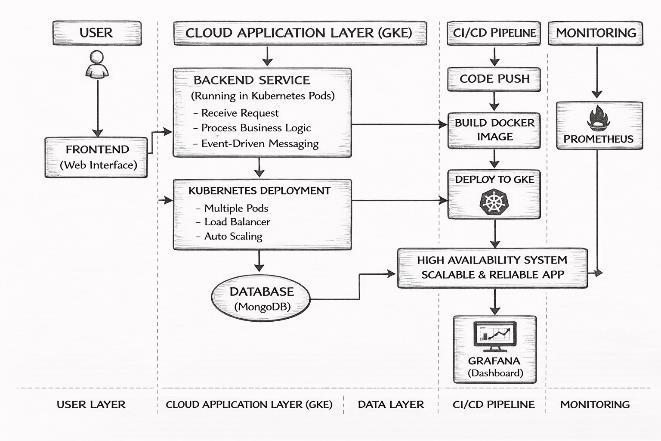
Fig - 1: BlockDiagramofProposedThree-TierArchitecture
International Research Journal of Engineering and Technology (IRJET) e-ISSN: 2395-0056
Volume: 13 Issue: 04 | Apr 2026 www.irjet.net p-ISSN: 2395-0072

5.1. STEP 1: APPLICATION DESIGN
Theapplicationisdesignedusingathree-tierarchitecturethat includes frontend, backend, and database layers. Each layer performsaspecificrole,whichimprovessystemorganization, maintainability,anddevelopmentefficiency.
5.2. STEP 2: CONTAINERIZATION
All components of the application are containerized using Docker.Thisensuresthattheapplicationrunsconsistently across different environments. It also simplifies dependency management and improves portability. By isolating each component,thesystembecomesmorescalableandreliable.
5.3. STEP 3: DEPLOYMENT ON GKE
The containerized application is deployed on Google KubernetesEngine(GKE).Kubernetesdeploymentsand services are configured to manage application components andensurecontinuousavailabilityofthesystem.
5.4. STEP 4: TRAFFIC MANAGEMENT
Kubernetesservicesandingresscontrollersareusedtoroute incoming user requests to the appropriate pods. Load balancing distributes traffic evenly across multiple instances, ensuringsmoothsystemperformance.
5.5. STEP 5: AUTO SCALING CONFIGURATION
The Horizontal Pod Autoscaler (HPA) is configured to automatically adjust the number of pods based on system load, such as CPU usage. This allows the system to efficiently handlebothlowandhightrafficconditions.
5.6. STEP 6: CI/CD
A CI/CD pipeline is implemented using GitHub Actions to automate the build and deployment process. Whenever code changes are made, the system automatically builds new containerimagesanddeploysthemtotheKubernetescluster.
5.7.
Prometheus is used to collect system performance metrics, while Grafana provides visual dashboards for monitoring. These tools help in tracking resource usage and identifying potentialissuesinrealtime.
5.8.
The system is tested under different traffic conditions to evaluate its scalability, performance, and reliability. Monitoring dashboards are used to analyze system behavior andensurestableoperation.
6.1.
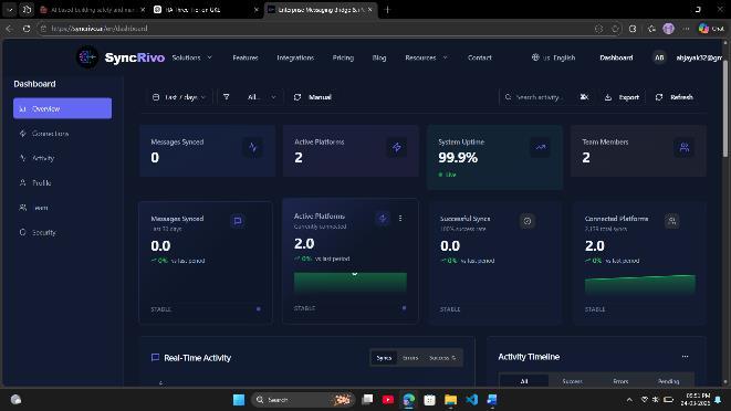
Thefrontendlayeractsasthemaininterfacebetweentheuser andthesystem.Itallowsuserstointeractwiththeapplication easily and access important information such as system status, performance metrics, and application data. The interface is designed to be simple, responsive, and userfriendly, ensuring smooth interactionacross different devices such as desktops, tablets, and mobile phones. This improves accessibilityandprovidesaconsistentuserexperience.
Thefrontendcommunicateswiththebackendbysendinguser requests and receiving responses in real time. This enables fast data exchange and ensures that users get updated informationwithoutdelay.
Overall, the frontend layer plays an important role in enhancing usability and providing a seamless interaction experience for users. The frontend interface is illustrated in Fig.3.
International Research Journal of Engineering and Technology (IRJET) e-ISSN: 2395-0056
Volume: 13 Issue: 04 | Apr 2026 www.irjet.net p-ISSN: 2395-0072
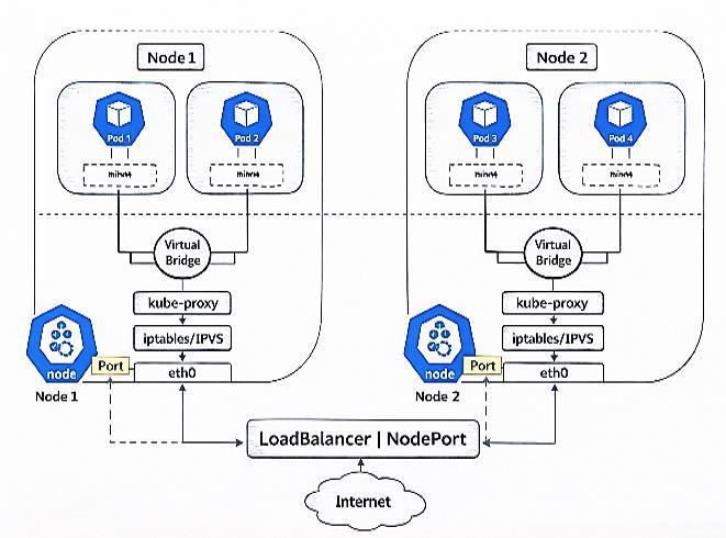
The backend layer is responsible for handling the core processing logic of the system. It receives requests from the frontend, validates them, and performs the required operations. The backend is deployed as multiple pods in the Kubernetes cluster, which improves availability and ensures fault tolerance. It supports real-time communication using WebSocketsandmanagesinteractionbetweentheapplication and the database layer. The backend deployment using KubernetespodsisshowninFig.4.
The backend includes proper logging and error-handling mechanisms, which help in debugging and improving system reliability. The system is designed using a stateless architecture, allowing efficient scaling and better load distribution across multiple pods. Security is maintained through request validation and access control mechanisms. The backend also provides efficient API handling to enable smooth communication between system components. Kubernetes orchestration features help the system automatically recover from failures and maintain continuous operation.Loadbalancingensuresthatincomingrequestsare evenly distributed across pods, improving overall performance. This design ensures fast response time and reliable service, even under changing workload conditions. Thebackendcanhandlemultipleconcurrentrequestswithout performance degradation. It efficiently processes incoming dataandensuresquickresponsedeliverytousers.
The use of containerized services improves system flexibility and simplifies deployment. This architecture supports seamlessscalabilityandenhancesoverallsystemefficiency.
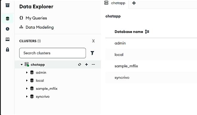
The database layer is responsible for storing and managing applicationdata, includinguser information, systemlogs,and operational records. It ensures secure storage and efficient data retrieval. A cloud-based database solution such as MongoDB Atlas is used to provide high availability and scalability. The backend communicates with the database to perform operations such as inserting, updating, deleting, and retrieving data based on user requests. The database is designed to handle large volumes of data efficiently while maintaining data integrity and security. Its scalable nature allows it to support growing application demands without affectingperformance. Thedatabasestructureispresentedin
The application is deployed on Google Kubernetes Engine (GKE), where Kubernetes manages the containerized environment efficiently. It handles the deployment, scaling, and overall operation of application components within the cluster. Incoming user traffic is distributed across multiple podsusingloadbalancing,whichpreventsanysingleinstance from becoming overloaded. This ensures smooth and stable system performance. To handle changing workload conditions,theHorizontalPodAutoscaler(HPA)isconfigured to automatically adjust the number of pods. When user demandincreases,additional podsarecreatedtomanagethe load. During periods of low traffic, the number of pods is reducedtooptimizeresourceusageandminimizeoperational costs. This dynamic scaling mechanism improves system efficiency, ensures high availability, and maintains consistent
International Research Journal of Engineering and Technology (IRJET) e-ISSN: 2395-0056
Volume: 13 Issue: 04 | Apr 2026 www.irjet.net p-ISSN: 2395-0072
performance under varying traffic conditions. The Auto
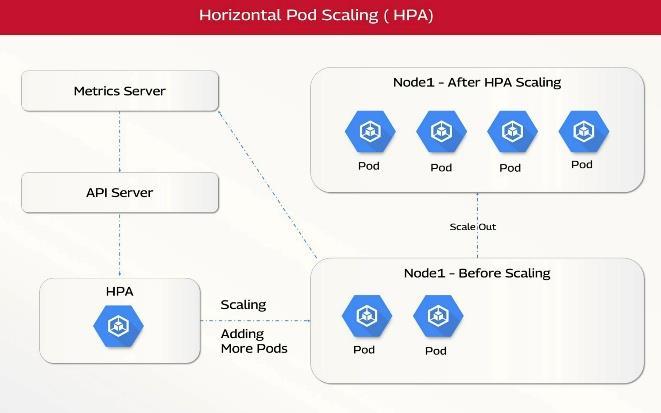
scalingandLoadBalancinginKubernetesshowninFig.6.
Fig - 6: AutoScalingandLoadBalancinginKubernetes
6.5. MODULE 5: CI/CD PIPELINE
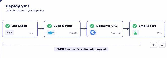
TheCI/CDpipelineisusedtoautomatetheprocessofbuilding and deploying the application using GitHub Actions. Whenever changes are made to the source code, the pipeline isautomaticallytriggered.Thepipelinebuildstheapplication, creates Docker images, and deploys them to the Kubernetes clusterwithoutmanualintervention.
Thisautomationreduceshumaneffort,minimizeserrors,and ensures consistency across deployments. By enabling continuous integration and continuous delivery, the system can release updates faster and more reliably. This improves development efficiency and helps maintain application stability.TheCI/CDworkflowisshowninFig.7.
6.6. MODULE 6: MONITORING AND DASHBOARD
Monitoringofthe systemisperformedusingPrometheusand Grafana. Prometheus is responsible for collecting important system metrics such as CPU usage, memory utilization, requestrate,andpodstatusfromtheKubernetescluster.
Grafana is used to visualize these metrics through interactive dashboards. These dashboards make it easy to understand systemperformanceandquicklyidentifyanyissues.
Themonitoringsetupprovidesreal-timevisibilityintosystem operations, helping administrators track performance, detect failures, and take necessary actions. This improves system reliability and ensures smooth operation under different workloadconditions.
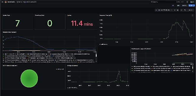
Under normal load conditions, the system operates with a limited number of pods, maintaining stable performance and efficient resource usage. When the traffic increases, Kubernetesautomaticallyscalesthenumberofpodstohandle the increased load. This increase in pods can be clearly observed in the monitoring dashboard, where the number of activepodsandsystemmetricssuchasCPUusageandrequest rate also increase. The monitoring dashboard is displayed in Fig.8.
Fig – 8: MonitoringDashboardUsingGrafanaShowingNormal
Theimplementedsystemwastestedunderdifferentworkload conditions to evaluate its performance, scalability, and reliability. The integration of the frontend, backend, and database layers was successfully verified, ensuring smooth communication between all components. The deployment of the application using Docker containers and Kubernetes provided a stable and flexible execution environment. During testing, the system handled multiple user requests simultaneouslywithoutanynoticeabledropinperformance.
When the workload increased, Kubernetes automatically scaled the number of pods using the Horizontal Pod
International Research Journal of Engineering and Technology (IRJET) e-ISSN: 2395-0056
Volume: 13 Issue: 04 | Apr 2026 www.irjet.net p-ISSN: 2395-0072
Autoscaler (HPA). This helped maintain consistent response time and prevented service interruptions. The system was abletoadapteffectivelytochangingtrafficconditions.
The CI/CD pipeline implemented using GitHub Actions automated the build and deployment process. This reduced manual effort and enabled faster and more reliable updates. New changes were deployed smoothly without affecting systemavailability.
Monitoring tools such as Prometheus and Grafana provided real-time insights into system performance. Key metrics, including CPU usage, memory utilization, request rate, and pod status, were continuously monitored. These insights helped identify potential issues and improve overall system efficiency. The system remained stable even during scaling operations, and failed pods were automatically restarted by Kubernetes,demonstratingstrongfaulttolerance.
Overall, the results show that the proposed architecture can effectively support scalable, reliable, and efficient application performance in a cloud environment. The combination of containerization, orchestration, automation, and monitoring significantly improves system stability and operational efficiency.
Thisworkpresentedahigh-availabilitythree-tierarchitecture deployed on Google Kubernetes Engine (GKE) for modern cloud-based applications. The system combines containerization, orchestration, and automation to achieve betterscalability,reliability,andefficientuseofresources.
Kubernetesplaysakeyrolebyprovidingloadbalancing,fault tolerance,andautomaticscaling,whichallowstheapplication to handle changing traffic conditions without affecting performance. The use of a CI/CD pipeline ensures faster and more consistent deployment, while monitoring tools offer continuousinsightsintosystemperformance.
The results show that the system operates reliably with minimal downtime and can adapt effectively to dynamic workloads.Themodulardesignofthearchitecturealsomakes iteasytomaintainandextendwithnewfeaturesinthefuture. Thisworkuniquelyintegratesauto-scaling,CI/CDautomation, andreal-timemonitoringintoasingleunifiedarchitecturefor improvedperformance.
Overall, the proposed solution provides a practical and efficient approach for developing scalable and resilient applicationsinmoderncloudenvironments.
[1] M.LiandR.Gupta,“HighAvailabilityandAuto-Scalingin Containerized Cloud Environments,” IEEE Trans. Cloud Comput.,vol.13,no.1,pp.88–99,2025.
[2] J. Doe and A. Patel, “CI/CD Pipeline Automation Using GitHub Actions,” IEEE Softw., vol. 41, no. 3, pp. 60–67, 2024.
[3] R. Sharma and P. Nair, “A Review of Cloud-Native Security and Kubernetes-Based Architectures,” IEEE Access,vol.13,pp.12045–12060,2025.
[4] B. Burns, B. Grant, D. Oppenheimer, E. Brewer, and J. Wilkes, “Borg, Omega, and Kubernetes,” IEEE Cloud Comput.,vol.3,no.3,pp.70–77,2016.
[5] M.Satyanarayanan,“TheEmergenceofEdgeComputing,” IEEEComput.,vol.50,no.1,pp.30–39,2017.
[6] T. Hightower, B. Burns, and J. Beda, Kubernetes: Up and Running,O’ReillyMedia,2017.
[7] P. Jamshidi, C. Pahl, and N. C. Mendonça, “Pattern-Based Multi-CloudArchitectureMigration,”IEEESoftw.,vol.34, no.3,pp.30–36,2017.
[8] A. Balalaie, A. Heydarnoori, and P. Jamshidi, “Microservices Architecture Enables DevOps,” IEEE Softw.,vol.33,no.3,pp.42–52,2016.
[9] N. Dragoni et al., “Microservices: Yesterday, Today, and Tomorrow,”IEEESoftw.,vol.35,no.3,pp.21–27,2018.
[10] C. Pahl, “Containerization and the PaaS Cloud,” IEEE CloudComput.,vol.2,no.3,pp.24–31,2015.
[11] J. Humble and D. Farley, Continuous Delivery: Reliable SoftwareReleases,Addison-Wesley,2010.
[12] G. Kim, J. Humble, P. Debois, and J. Willis, The DevOps Handbook,ITRevolutionPress,2016.
[13] L. Bass, I. Weber, and L. Zhu, DevOps: A Software Architect’sPerspective,Addison-Wesley,2015.
[14] B. Turnbull, The Docker Book: Containerization Is the NewVirtualization,2014.
[15] J. Thönes, “Microservices,” IEEE Softw., vol. 32, no. 1, pp.116–116,2015.
[16] W.Chen,P.K.S.K.S.Jayaraman,andA.Ranjan,“CloudBased Application Monitoring,” IEEE Cloud Comput., vol.5,no.2,pp.26–35,2018.
[17] M. Villamizar et al., “Evaluating Monolithic and MicroserviceArchitectureforCloudApplications,”IEEE Latin America Transactions, vol. 13, no. 12, pp. 3905–3912,2015.
[18] X.Xu,“FromCloudComputingtoCloudManufacturing,” IEEE Transactions on Industrial Informatics, vol. 8, no. 2,pp.254–262,2012.
[19] P. Mell and T. Grance, “The NIST Definition of Cloud Computing,” IEEE Security & Privacy, vol. 7, no. 6, pp. 61–63,2011.