
International Research Journal of Engineering and Technology (IRJET) e-ISSN: 2395-0056
Volume: 13 Issue: 01 | Jan 2026 www.irjet.net p-ISSN: 2395-0072
International Research Journal of Engineering and Technology (IRJET) e-ISSN: 2395-0056
Volume: 13 Issue: 01 | Jan 2026 www.irjet.net p-ISSN: 2395-0072
Tejas gowda L C1 , Dr. T Kiran2
Master of Technology, Department of Civil Engineering, Major: Earthquake Engineering, University of Visvesvaraya College of Engineering, Bengaluru, Karnataka, India
Associate Professor, Department of Civil Engineering, University of Visvesvaray College of Engineering, Bengaluru, Karnataka, India,
Abstract - This study presents an experimental investigation on the flexural behaviour of M30 grade reinforcedconcrete beams reinforced with HYSD steel, GFRP, and hybrid reinforcement configurations. Four beams with identical geometry were tested under two-point loading to examine load–deflection response, cracking behaviour, stiffness characteristics, and failure mechanisms. The results showedthatHYSD-reinforcedbeamsexhibitedhigherstiffness, lower deflections, and improved crack control, indicating superior serviceability performance. GFRP-reinforced beams demonstratedhigherdeformabilitywithwidercrackopenings due to the lower modulus of elasticity of GFRP bars. Hybrid beams exhibited intermediate behaviour, where beams with HYSD as main reinforcement behaved closer to steelreinforced beams, while beams with GFRP as main reinforcement showed enhanced deformation capacity. The studyhighlightsthesignificantinfluenceofreinforcementtype and configuration on the flexural performance of reinforced concrete beams.
Key Words: Glass Fiber Reinforced Polymer (GFRP), High Yield Strength Deformed (HYSD), Cracking Behaviour, Monotonic Loading, Stiffness Degradation
Concretebeamsaretypicallyconcretebeamsreinforcedwith HYSDsteeltohelpbeartensileforces.Recently,thereseems tobeatrendtowardusingFiberReinforcedPolymer(FRP) andspecificallyGlassFiberReinforcedPolymer(GFRP)asan alternative to steel for providing tensile strength in beams becauseofitsveryhighstrength-to-weightratioandpossible corrosion resistance. Most of the research carried out on concretebeamsreinforcedwithGFRPwasbasedonflexural performance compared to structural performance characteristicswithreferencetocrackingpatterns,stiffness, load-deflectionresponse,andfailuremode,focusingmainlyon thecharacteristicsoftheconverted effects ofconventional beams with those cast using steel reinforcements [7, 6]. Experimental assessments always claimed that beams in GFRP compared to beams in steel deflect more with width cracksduetolessmodulusofelasticityinGFRPbars[7].Ithas alsobeen established that thesteel-reinforced beams yield beforefailureandareductileinnatureunderconsideration, but the GFRP-reinforced concrete beams typically fail in a
brittlemannerwithoutcommittingconsiderableamountsof plasticdeformation[6].
Studies on continuous FRP-reinforced concrete beams revealed that moment redistribution occurs owing to stiffnessdegradationandnonlinearityofconcreteinsteadof yielding of reinforcement [2]. From the experimental investigation concerning over reinforced GFRP concrete beams, concrete crushing governed the failure, which is knowntobeamorestableanddesirablefailurecomparedto thatofsuddenbarrupture[5].Onaccountofinvestigations into crack characteristics, it was confirmed that crack spacing in GFRP-reinforced beams is generally larger in comparisonwiththatofsteel-reinforcedones;suchafactor would seriously affect serviceability performance [4]. Experimental investigations posit that increasing the axial stiffnessofGFRPreinforcementwoulddefinitelyimprovethe flexuralstrengthbutataconsiderablyreduceddeflectionand crack widths [2]. A comparison of different design codes indicatedthatwhileACI440.1Randtheotheravailablecodes underestimate deflections of GFRP-reinforced beams, it is necessarytodevelopamoreappropriateserviceabilitymodel [1].
However,itisafactthathugenumbersofresearchstudies identify either steel concrete or GFRP concrete beam behavior. A very small number of studies have been done comparativelyunderalmostsimilarmaterialparticularswhile keepingthesamegeometryandloadingconditionsforboth HYSDsteelandGFRPreinforcedconcretesystems.Thegapof directcomparisonsdoesnotallowaclearunderstandingof relative structural performance between these two reinforcementsystems.Hencethisintendedstudywouldfill such a gap by conducting experimental analyses of the flexural behaviorof gradeM30reinforced concrete beams. Thescopeofthestudyincludessuchimportantperformance parameters such as load-deflection response, cracking behavior,stiffnesscharacteristics,andfailuremodesforthe comparative assessment of structural performance differences between concrete beams reinforced with steel andGFRP.
International Research Journal of Engineering and Technology (IRJET) e-ISSN: 2395-0056
Volume: 13 Issue: 01 | Jan 2026 www.irjet.net p-ISSN: 2395-0072
Foursimplysupportedconcretebeamshavebeenfabricated, andweretestedunderflexuralloading.Allbeamspecimens were made with the same geometric dimensions having a width of150 mm,anoverall depthof 200mm,and a clear span of 1200 mm. Average clear covering of 25 mm were provided for all reinforcements. The longitudinal reinforcement consisted of 12 mm diameter bars, while transverse reinforcement comprised of 8 mm diameter stirrups placed at a constant spacing of 100 mm center to center full span. 135° inclined stirrups to ensure effective anchoring and total concrete confinement. The beam specimenswereclassifiedbasedontypesofreinforcement. BeamTypeIwasfullyreinforcedwithHYSDbarsunderboth longitudinalandtransverseloadings.BeamTypeIIwasalso completely reinforced with GFRP bars under both longitudinal and transverse reinforcements. Beam Type III receiveditsmainlongitudinalreinforcementwithHYSDsteel barsanditstransversereinforcementwithGFRPbarsusedas stirrups while Beam Type IV was longitudinally reinforced with GFRP bars and used HYSD steel bars as stirrups.
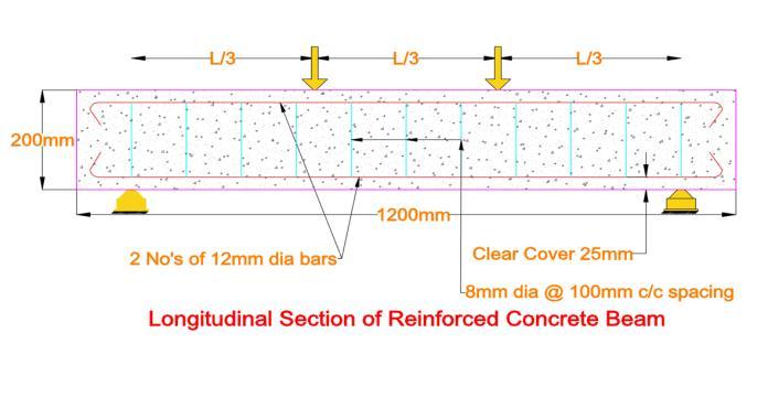
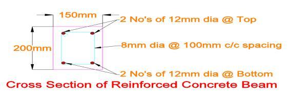
Table -1: Specimenidentificationanddetails.
Specimen details and identifications
Specimen ID Reinforce menttype Top Reinforce mentBar Bottom Reinforce mentBar Stirrups
MH-SH-B1 HYSD HYSD HYSD HYSD
MG-SG-B2 GFRP GFRP GFRP GFRP
MH-SG-B3 Hybrid HYSD HYSD GFRP
MG-SH-B4 Hybrid GFRP GFRP HYSD
Themix-designofexperimentalconcretewasdoneusing Ordinary Portland Cement of 43-grade quality as per IS 12269:2013[8].ManufacturedSand(M-sand)wasusedas fine aggregate and crushed angular coarse aggregate of nominalmaximumsizeof20mmwastaken.Cleandrinking water free of any impurities, salts, and oils, and organic matter was used for mixing and curing. Following the guidelinesIS10262:2019,theconcretewasmixedwiththe intent of achieving M30 design strength. The modulus of elasticityofHYSDsteelreinforcementhasbeentakenas200 GPaaccordingtoIS456:2000.TheFe500gradepossessesa characteristic tensile strength of 500 MPa. The modulus of elasticityofGFRPreinforcementhasbeenadoptedfromdata basedontheprovisionswiththetypicalrangeof40-60GPa whilethetensilestrengthvaluesarebetween800-1200MPa asdefinedinIS18255:2023.AccordingtoIS10262:2019,the concretemixforthisstudyisestablishedforM30grade.The water–cementratiois0.43.However,asuitablequantityof super plasticizer was added to improve the workability withoutcausingmuchvariationinstrengthcharacteristics
Table -2: Mixproportiondetails.
Quantities of Material per cubic meter of concrete OPC53
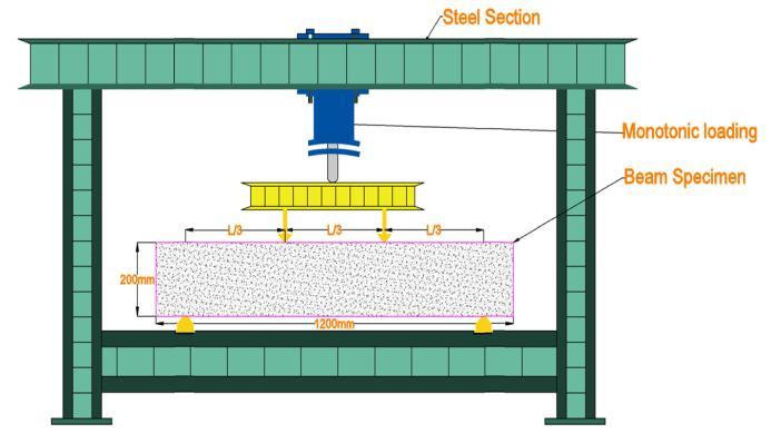
Two simple supports were erected under the test specimensandsubjectedtoanupperloadingframebythe flexuralload.A30Tcapacityhydraulicactuatorboltedtothe loadgottransmittedthroughtheloadingsetuptothebeam, dividing in two equal twin-point loads working symmetricallyonthetestsetup.Withthisconfigurationof loading, a constant moment region exists between each loadingapplication.
Mid-span of the specimen was attached to a High precision LVDT to record vertical displacement during loadingfordeflectionmeasurement.Monitoringtheloadand deflection is put in place to make sure that the data is continuouslyregisteredthroughoutthetestingprocess.The schemingofflexuraltestsetupcanbeseenfromthefigure. Anarrangementdevelopedfortheinstrumentationsystem can provide reasonable accuracy in measurements of structureresponsesduringtestsofflexuralloading.
Theverticaldisplacementsatmid-spanofthebeamwere recordedwitha highlypreciseLVDTwithbothofitsends firmlyattachedtoafreereferenceframetoavoidanyground
International Research Journal of Engineering and Technology (IRJET) e-ISSN: 2395-0056
Volume: 13 Issue: 01 | Jan 2026 www.irjet.net p-ISSN: 2395-0072
effectfromsupportmovements.Loadwasrecordedthrough a load cell. All the measured quantities were logged automaticallyaftercertainintervalsthroughacomputerized dataacquisitionsystemforfurtheranalysis.
3.1 Mechanical properties
The characteristics of the concrete were tested at 28 days where M30 concrete exhibits systematic strength development with curing age in the order of compressive strength, flexural strength, and split tensile strength. Compressive strength shows the highest rate of increase, withgainsof36.14%between7and14daysandafurther 40.36%between14and28days,indicatingrapidhydration andeffectiveload-carryingcapacitydevelopment.Flexural strength follows a similar but relatively moderate trend, increasingby4.34%from7to14daysandby29.70%from 14 to 28 days, reflecting gradual improvement in tensile resistance of the concrete matrix. Split tensile strength at room temperature shows comparatively lower but steady enhancement with age, governed mainly by bond development and microstructural refinement. Overall, the roomtemperatureperformanceestablishesaclearhierarchy ofstrengthdevelopment,withcompressivestrengthbeing themostdominant,followedbyflexuralstrengthandthen split tensile strength, serving as a reliable reference for evaluatingthermalexposureeffects.
With regard to the flexural response observed during the experimentation,HYSDbeamsprovedtobebetterinterms of utmost willingness and serviceability than GFRPreinforcedbeams.Afterfirstcracking,thedeflectionsatthe mid-spanoftheHYSDbeamsweresignificantlylowerthan those of the GFRP ones, with reductions in the range of around 60-65% when compared to GFRP beams for peak load. It can be understood that such a higher stiffness is actually due to a highly elastic modulus of the reinforcing steel.ThedifferentpropagationofcracksintheHYSDbeams wasundercontrolandthewidthsofcrackswereabout50% smallerthanthosefoundinGFRPbeams,pointingtomuch bettercrackdistributionandstiffeningundertension.Onthe contrary,GFRP-reinforcedbeamsweremoredeformableas wellashadwidercrackopeningswhichshowedthatthey could have kept safe, but their serviceability performance whilesubjectedtoflexuralloadsfailedtomatchthatofthe HYSD-reinforcedbeams.
Consequently, the flexural behavior of beams with hybrid reinforcement displayed a striking dependence on thearrangementofreinforcement.Anobservationwasmade that the beam having HYSD bars as main longitudinal reinforcementandGFRPbarsasstirrupsunderwentdelayed firstcrackinganda relativelystiffpost-crackingresponse, thereby indicating an efficient contribution to flexural resistancebysteelintension.Incomparison,thebeamwith GFRP bars acting as main longitudinal reinforcement and HYSD bars as stirrups had earlier cracking with a postcrackingresponsethatcouldbeclassifiedasmoreflexible, whichwasareflectionofthelowermodulusofelasticityof GFRP bars .In a comparison, the hybrid beam with HYSD mainsshowedlessermidspandeflectionandstiffness,while thehybridbeamwithGFRPmainscarriedahigherloadbut exhibited a greater degree of deflection, demonstrating greaterdeformability.Thus,itcouldbesaidthattheuseof HYSD bars as main reinforcement improves its stiffness properties and crack control, and the use of GFRP bars as main reinforcement increases ductility and deformation capacity;thisunderlinestheimportanceoftheconfiguration ofthereinforcementsystemforhybridbeamperformance.
MH:SH-B1 exhibits the highest slope values, indicating maximuminitialstiffnessandexcellentcrackcontrol,along with relatively low ultimate deflection that reflects stable and ductile behavior governed by yielding of HYSD reinforcement.MG:SG-B2showstheminimumslopevalues, representing lower initial stiffness and earlier crack initiation, while exhibiting very high deflection at failure,
International Research Journal of Engineering and Technology (IRJET) e-ISSN: 2395-0056
Volume: 13 Issue: 01 | Jan 2026 www.irjet.net p-ISSN: 2395-0072
indicating large deformation capacity and pseudo-ductile behavior due to GFRP main reinforcement. MH:SG-B3 demonstrates lower slope values than MH:SH-B1 but still maintainsconsiderablestiffness,confirmingeffectivecrack control through the combination of HYSD main bars and GFRPstirrups,withmoderateultimatedeflection.MG:SH-B4 representsahybridconfigurationshowingmoderateslope and ultimate deflection values, achieving a balanced responsewithreasonablestiffness,controlledcracking,and sufficientdeformationcapacity,therebyofferinganoptimal compromisebetweenstrength,stiffness,andductility.
Table -3: Flexural test results of Beams
Specimen ID
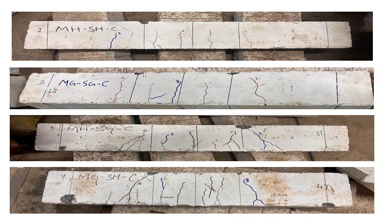
B1 shows the best crack control among all specimens, characterizedbycloselyspacedandfineflexuralcracksthat develop gradually with load. The presence of HYSD reinforcement ensures high initial stiffness, delayed crack initiation,andastableductilefailuregovernedbyyieldingof steelfollowedbyconcretecrushinginthecompressionzone.
B2(MG:SG-B2)performsinferiortoB1intermsofcrack control.Cracksinitiateatlowerloadlevelsandarefewerbut significantly wider,indicatinglowerstiffnessand reduced tensilerestraint.Failureoccursthroughextensiveflexural crackingaccompaniedbylargedeflections,demonstrating pseudo-ductile behavior due to the absence of yielding in GFRPmainreinforcement.
B3 (MH:SG-B3) performs better than B2 but remains slightly inferior to B1. Cracks are moderately spaced with controlledwidths,reflectingimprovedstiffnessduetoHYSD mainbars.Failureisflexure-dominatedwithgradualcrack propagation, showing a stable response and better crack distributioncomparedtoGFRP-onlyreinforcement.
B4 (MG:SH-B4) exhibits a balanced crack pattern betweenB1andB2.Crackwidthsandspacingaremoderate, indicating reasonable stiffness and effective stress redistribution.Failureoccursinacontrolledflexuralmanner with significant deformation capacity, making B4 structurallymoreefficientthanB2whilestillnotmatching thecrackcontrolachievedbyB1.
B1consideredas a referenceultimatedeflection, showing the most controlled and ductile structural response. B3 (MH:SG-B3) develops 84.75% load capacity and 85.20% stiffnessrelativetoB1,whileitsultimatedeflectionreaches 121.40% of B1, indicating slightly reduced stiffness but stable post-cracking behavior with good deformation capacity.
B4(MG:SH-B4)achieves74.60%loadcapacityand75.10% stiffness compared to B1, with an ultimate deflection of 139.85%ofB1,reflectingabalancedcompromisebetween strengthreductionandenhanceddeformability.
B2(MG:SG-B2)showstheloweststructuralresistancewith 59.30% load capacity and 54.80% stiffness of B1, but exhibits the highest ultimate deflection at 171.60% of B1, confirmingreducedstiffnessandpronouncedpseudo-ductile behavior.
Consideringtheoverallstructuralperformanceofall four beam specimens (B1–B4), the following comparative recommendationsaredrawn.B1(MH:SH-B1)demonstrates thehighestloadcapacity,maximumstiffness,andsuperior crackcontrol,makingitthemostsuitableoptionforprimary load-bearing members where serviceability and strength governdesign.B3(MH:SG-B3)performsclosesttoB1,with only a moderate reduction in stiffness and load capacity while offering improved deformation capacity, and is thereforerecommended wheredurability enhancement is required without significantly compromising structural performance.B4(MG:SH-B4)providesabalancedresponse with moderate strength, stiffness, and higher deflection capacity,makingitappropriateforapplicationsdemanding an optimal compromise between rigidity and ductility. B2 (MG:SG-B2), although exhibiting the lowest stiffness and loadresistance,showsthehighestdeformationcapacityand pseudo-ductile behavior, and is recommended only for conditionswherelargedeformationtoleranceandcorrosion resistanceareprioritizedoverstrengthandserviceability.
[1] Nuha Hussein, etal., “Experimental and numerical investigationonthebehaviorofhybridconcretebeams reinforced with GFRP bars after exposure to elevated temperature,” Structures, vol:28, 2020 Pages:537–551
[2] ZeinSaleh,etal.,“FlexuraldesignofGFRPbarreinforced concrete beams: An appraisal of code
International Research Journal of Engineering and Technology (IRJET) e-ISSN: 2395-0056
recommendations,”JournalofBuildingEngineering,vol: 25,2019,ArticleNo.:100794.
[3] C.Barris,etal.,“Experimentalstudyoncrackwidthand crackspacingforGlass-FRPreinforcedconcretebeams,” EngineeringStructures,2016.
[4] Ashraf F. Ashour and Ilker Fatih Kara, “Size effect on shear strength of FRP reinforced concrete beam,” Composites:PartB,volume:60,2014,Page:612–620.
[5] Valter Carvelli and Marco Andrea Pisani, “High TemperatureEffectsonConcreteMembersReinforced with GFRP Rebars,” Composites: Part B, volume: 45, 2013,Page:130–141
[6] AbdelmonemMasmoudi,etal.,“Newparameterdesignof GFRPRCbeams,”ConstructionandBuildingMaterials, volume:29,2012,Page:627–632.
[7] Raed Al-Sunna, etal., “Deflection behaviour of FRP reinforcedconcretebeamsandslabs:Anexperimental investigation,”Volume43,2012,Page2125–2134.
[8] IS12269:2013.OrdinaryPortlandCement,53Grade Specification. Bureau of Indian Standards, New Delhi, India.
[9] IS 10262:2019. Concrete Mix Proportioning Guidelines. Bureau of Indian Standards, New Delhi, India.
[10] IS456:2000.PlainandReinforcedConcrete Codeof Practice. Bureau of Indian Standards, New Delhi, India.
[11] IS 18255:2023. Glass Fibre Reinforced Polymer (GFRP) Bars for Concrete Reinforcement Specification. Bureau of Indian Standards, New Delhi, India.
Volume: 13 Issue: 01 | Jan 2026 www.irjet.net p-ISSN: 2395-0072 © 2026, IRJET | Impact Factor value: 8.315 | ISO 9001:2008
|