
International Research Journal of Engineering and Technology (IRJET) e-ISSN: 2395-0056
Volume: 13 Issue: 03 | Mar 2026 www.irjet.net p-ISSN: 2395-0072
International Research Journal of Engineering and Technology (IRJET) e-ISSN: 2395-0056
Volume: 13 Issue: 03 | Mar 2026 www.irjet.net p-ISSN: 2395-0072
Prashanth S1 , R. Rajashekar²
1M.Tech Student, Dept. of Mechanical Engineering, UVCE, Bengaluru, India
²Professor, Dept. of Mechanical Engineering, UVCE, Bengaluru, India
Abstract - Clevis-type pin-lug joints are commonly used for load transmission in mechanical and structural components. Although these joints have a simple configuration, high stress concentration develops near the pin-hole interface due to localized contact between the pin and the lug, which significantlyaffects joint strength anddurability.Inthiswork, an experimental investigation was carried out on an Aluminium 6061 clevis-type pin-lugjoint usingthree-element strain rosettes. Surface strains near the pin-hole region were measured for different applied loads and hole diameters and converted into principal stresses and equivalent Von Mises stress usingplane stress relationships. Finite element analysis using ANSYS was performed to simulate stress distribution. The results show that principal and Von Mises stresses increase almost linearly with load, and larger hole diameters produce higher stress due to increased clearance. Numerical results are close to experimental observations. This combined approach supports improved design of pin-connected components.
Key Words: Clevis Joint, Contact Stress, Strain Rosette, Aluminum 6061, Finite Element Analysis, Pin-Lug Joint, Bearing Stress
Mechanicaljointsutilizingpin-lugorclevis-styleconnections are essential components in various engineering applications such as aerospace, marine, industrial, and automotivesystems.Thesejointsarewidelyadopteddueto theirsimplegeometry,easeofassembly,andefficientload transmission.However,thestressdevelopednearthepinholeinterfaceishighlynon-uniformduetolocalizedcontact betweenthepinandthehole.
The applied load is transferred only through a limited contact region, depending on factors such as clearance, materialproperties,platethickness,andloadingdirection. Asaresult,highlocalizedstressesdevelopnearthecontact zone, which are usually higher than those predicted by nominal bearing stress formulas. Under repeated loading conditions,theseregionsmayexperiencewear,deformation, andcrackinitiation,leadingtostructuralfailure.
Conventionalanalyticalmethodsgenerallyassumeuniform pressuredistributionoverthecontactarea,whichisrarely valid in practical joints, especially under clearance-fit and
thinplateconditions.Therefore,experimentalinvestigation isnecessarytostudytherealstressbehaviourinpin-loaded joints. Strain gauge rosettes provide accurate strain measurements near stress concentration zones without significantlyalteringthestressfield.
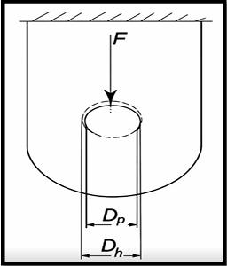
Inthisstudy,anexperimentalandnumericalinvestigationis carried out on Aluminium 6061 clevis-type pin-lug joints using strain rosettes and finite element analysis. The objectiveistoanalysecontactstressdevelopmentnearthe pin-holeinterfaceandtoexaminetheinfluenceofclearance onlocalizedstressbehaviour.
Severalresearchershaveinvestigatedthestressbehaviourof pin-connected joints and plates with circular holes under different loading conditions. The presence of a hole in a structural member leads to stress concentration, which significantly reduces the load-carrying capacity of the component.
Aradhye and Kulkarni studied stress concentration in isotropic and orthotropic plates with circular holes using strain gauge rosettes and experimental techniques. Their resultsindicatedthat strain rosettesare effective tools for evaluating localized stress fields around holes. Kaw and othersanalysedcompositeandmetallicjointsandreported that clearance and contact conditions play a major role in stressdistribution.
Previous studies have also shown that conventional analytical methods based on uniform bearing pressure assumptions are inadequate for predicting actual stress distributioninpin-lugjoints.Finiteelementanalysishasbeen
International Research Journal of Engineering and Technology (IRJET) e-ISSN: 2395-0056
Volume: 13 Issue: 03 | Mar 2026 www.irjet.net p-ISSN: 2395-0072
widely used to simulate contact behaviour and stress concentration in such joints. However, experimental validationisnecessarytoensuretheaccuracyofnumerical models.
From the literature, it is observed that limited work is available on combined experimental and numerical investigation of thin Aluminium 6061 clevis joints using strain rosettes. Therefore, the present study focuses on analyzing contact stress behaviour through experimental measurementsandfiniteelementsimulation.
The present investigation involves both experimental testing and finite element analysis of a clevis-type pin-lug joint made of Aluminium 6061-T6. The methodology adoptedinthisstudyisdividedintospecimenpreparation, experimentalsetup,strainmeasurement,stresscalculation, and simulation.
3.1
The clevis-type lug specimens were fabricated from Aluminium6061plateofthickness3.4mm.Holesofdifferent diameters were drilled at the center of the specimens to studytheeffectofclearanceoncontactstressbehaviour.The specimenwasweldedtoaflatplatewhichwouldbeusedto holdthespecimenwiththehelpofcclampduringloading.
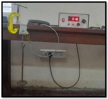
The experimental setup consists of a loading frame, clevis joint assembly, loading pan, c clamp and weight set. The specimen was mounted vertically, and load was applied gradually through dead weights. Proper alignment was ensuredtoavoideccentricloading.
3.3 Strain Measurement
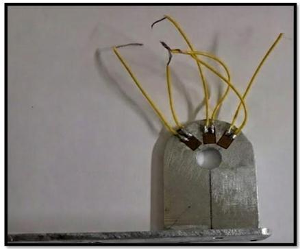
Three- element strain gauge rosettes (BF350, 350Ω) with gauge orientations -45°, 90° and +45°. They were bonded
near the pin-hole interface where high stress is expected Surfacepreparationwascarriedbyfinesandingandacetone cleaning to ensure proper bonding of strain gauges. The straingaugeswereconnectedtoadigitalstrainindicator,and strainreadingswererecordedforeachloadincrement.
The measured strain values were converted into stress componentsusingplanestressrelations.Principalstresses, maximumshearstress,andequivalentVonMisesstresswere calculatedusingstandardstresstransformationequations. These values were used to analyse the contact stress behaviour near the pin-hole interface. For -45°/90°/+45° configuration the directions are denoted as ε₁ , ε2 and ε3, respectively.
The normal and shear stresses in the x-y coordinates are calculatedbythefollowingplanestressequations:
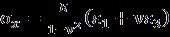
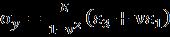

where:
σx ,σy =Normalstresses
τxy =In-planeshearstress
ε₁,ε₂,ε₃=Measuredstrains
3.4.1
The principal stresses are calculated using the following relation:
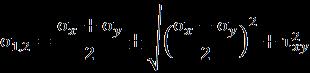
where:
σ₁=maximumprincipalstress
σ₂=minimumprincipalstress
International Research Journal of Engineering and Technology (IRJET) e-ISSN: 2395-0056
Volume: 13 Issue: 03 | Mar 2026 www.irjet.net p-ISSN: 2395-0072
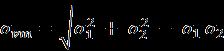
Sincethelugplateisrelativelythin,theout-of-planestress componentwasneglected(σ₃=0).Basedonthisassumption, theequivalentvonMisesstresswascalculatedusing:
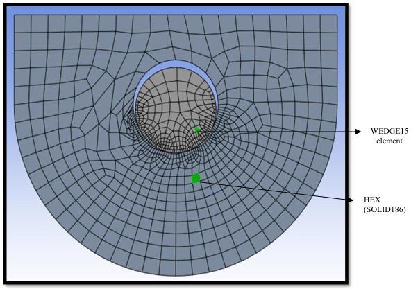
Solid works were used for model creation and ANSYS Workbenchwasusedfor3Dsimulationofpin-lugassembly. SOLID186hexahedralelementsandwedge15elementswere used with mesh refinement at pin-hole interface (0.2 mm element size). CONTA174 contact and TARGE170 target elementsdefinedatpin-holeboundary.Frictionlessboundary condition.Fixedsupportatlugbaseandthepinwasfixedinx andzdirectiontopreventrigidbodymotion.Thetensileload wasappliedinmatchingwithexperimentalconditions.
4. RESULTS AND DISCUSSION
Thestrainvaluesmeasuredexperimentallywereconverted into stress components, principal stresses, and Von Mises stress using the relations discussed in Section 3.4. The experimental strain readings for the three specimens A,B, andCwithholediametersof10mm,10.5mm,and11mm, respectively,arepresentedinTables1-3.
Table -1: ExperimentalstrainvaluesforSpecimenA(10 mmhole)
Table -2: ExperimentalstrainvaluesforSpecimenB(10.5 mmhole)
Table -3: ExperimentalstrainvaluesforSpecimenC(11 mmhole)
Tables1-3showthevariationofstrainin-45°,90°,and+45° directions with applied load for the three specimens. It is observedthatstrainincreasesalmostlinearlywithincreasing load,indicatingelasticbehaviourofthematerialwithinthe appliedloadrange.Thistrendconfirmsthatthespecimens deform elastically and no permanent deformation occurs underthetestedconditions.Maximumstresswasobserved near the loading direction at the edge of the hole due to localized bearing contact between the pin and lug. Minor variations among the specimens are attributed to manufacturingtolerancesandexperimentaluncertainties.
Table -4:PrincipalstressvaluesforSpecimensA,BandC
The principal stresses were calculated from the measured strain values using the stress transformation equations is shown in Table - 4. The variation of maximum principal
International Research Journal of Engineering and Technology (IRJET) e-ISSN: 2395-0056
Volume: 13 Issue: 03 | Mar 2026 www.irjet.net p-ISSN: 2395-0072
stress(σ₁)andminimumprincipalstress(σ₂)withapplied loadshowsanalmostlineartrendforallthreespecimens.
ForSpecimenA,σ₁increasedsteadilywithloadandreached itsmaximumvalueat12kg.Similartrendswereobservedfor SpecimensBandC,withhigherstressvaluesforlargerhole diameters. The increase in principal stresses with hole diameterismainlyduetoincreasedclearanceandreduced contactarea.Theresultsindicatethatmaximumtensilestress occurs near the loading direction at the edge of the hole, whilecompressivestressdevelopsontheoppositeside.
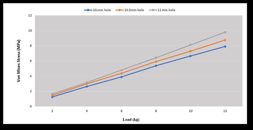
-5: VariationofVonMisesstresses(σvm)withload
Fig.5showsthevariationofVonMisesstresswithapplied loadforthethreespecimens.ItisobservedthatVonMises stress increases almost linearly with increasing load, indicatingelasticbehaviourwithinthetestedrange.Athigher loadlevels,SpecimensBandCexhibithigherstressvalues comparedtoSpecimenAduetoincreasedholediameterand clearance. The reduced contact area results in localized bearingstressandhigherstressconcentration.
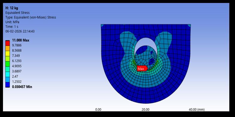
6:
TheVonMisesstresscontourobtainedfromfiniteelement analysis is shown in Fig. 6. High stress concentration is observednearthepin-holecontactregion,particularlyalong theloadingdirection.Themaximumstressoccursattheedge oftheholewheredirectcontactwiththepintakesplace.
Table -5:Variationofequivalent(VonMises)stressfor differentholediameterswithload
Table 5 presents the variation of equivalent (Von Mises) stressfordifferentholediametersunderappliedloading.Itis observedthatVonMisesstressincreaseswithincreasingload forallspecimens.Foragivenload,specimenswithlargerhole diameters exhibit higher stress values due to increased clearance and reduced contact area. This confirms the influenceofholediameteronstressconcentrationinpin-lug joints.
Tovalidatethefiniteelementmodel,theexperimentalVon Misesstressvalueswerecomparedwiththecorresponding numerical results obtained from ANSYS. Since Aluminium 6061isaductilematerial,VonMisesstresswasconsideredas theprimarycriterionforcomparisonbetweenexperimental and numerical results. The comparison Experimental and FEAVonMisesStressispresentedinTable6
Table -6: comparisonExperimentalandFEAVonMises Stress
FromTable6,itisobservedthatthefiniteelementresults areincloseagreementwithexperimentalvaluesforallthree specimens. The deviation between experimental and numerical Von Mises stress values is within acceptable limits,indicatinggoodcorrelation.
The minor differences between experimental and FEA resultsmaybeattributedtoidealizedboundaryconditions, simplifications in contact modelling, material property
International Research Journal of Engineering and Technology (IRJET) e-ISSN: 2395-0056
Volume: 13 Issue: 03 | Mar 2026 www.irjet.net p-ISSN: 2395-0072
variations,andexperimentalalignmenterrors.Overall,the comparison confirms that the developed finite element modelisreliableforpredictingcontactstressbehaviourin clevis-typepin-lugjoints.
An experimental and numerical investigation was carried out to analyse the contact stress behaviour in Aluminium 6061 clevis-type pin-lug joints using strain rosettes and finiteelementanalysis.Theexperimentalresultsshowthat strain, principal stresses, and Von Mises stress increase almost linearly with applied load within the elastic range. Maximum stress concentration occurs near the loading direction at the edge of the hole due to localized bearing contactbetweenthepinandlug.Specimenswithlargerhole diametersexhibithigherstresslevelsbecauseofincreased clearanceandreducedcontactarea.
Finiteelementanalysispredictsstressdistributionpatterns thatareingoodagreementwithexperimentalobservations. The comparison between experimental and numerical resultsconfirmsthevalidityofthedevelopedfiniteelement model.Thecombinedexperimentalandnumericalapproach adopted in this study provides useful guidelines for improving the design and durability of pin-connected componentssubjectedtostaticloading.Theresultsofthis workcanassistengineersinminimizingstressconcentration andenhancingjointperformance.
[1] V. G. Aradhye and S. S. Kulkarni, “Use of Strain Gauge RosettetoInvestigateStressConcentrationinIsotropic andOrthotropicPlatewithCircularHole,”International Research Journal of Engineering and Technology (IRJET),vol.2,no.7,pp.958–962,2015.
[2] D. B. Kawadkar, D. V. Bhope, and S. D. Khamankar, “EvaluationofStressConcentrationinPlatewithCutout anditsExperimentalVerification,”InternationalJournal ofEngineeringResearchandApplications(IJERA),vol.2, no.5,pp.566–571,2012.
[3] M.D.Jagtap,B.D.Gaikwad,P.M.Pawar,andB.P.Ronge, “UseofStrainGagestoAnalyzetheBehaviourofRoller ConveyorChainStrip,”inProc.IRFInt.Conf.,Mar.2015, pp.35–38.
[4] N. F. Knight Jr., “Bearing-Load Modeling and Analysis Study for Mechanically Connected Structures,” NASA ContractorRep.NASA/CR-2006-214529,Dec.2006.
[5] Y.Li,R.Huang,S.Zhao,andJ.Wang,“Contactpressure analysisofpin-loadedlugwithclearance,”Advancesin MechanicalEngineering,vol.14,no.6,2022.
[6] T.Hong,F.Ding,F.Chen,H.Zhang,Q.Zeng,andJ.Wang, “MechanicalPropertiesof6061AluminiumAlloyunder CyclicTensileLoading,”Crystals,vol.13,no.8,pp.1–17, 2023.
[7] P. Sathyaprakash, V. Kulkarni, and K. S. Vishwanath, “FiniteElementAnalysisofLugJoint,”SSRNElectronic Journal,2022.
[8] R. Prasad, “Overview of Strain Gauge and its Various Applications,”InternationalJournalofEngineeringand AppliedSciences(IJEAS),vol.10,no.9,Sep.2023.
[9] L.S.Srinath,ExperimentalStressAnalysis,2nded.New Delhi,India:TataMcGraw-Hill,2006.
[10] S. Singh, Applied Stress Analysis: A Textbook for Engineering Students, 4th ed. Delhi, India: Khanna Publishers,2000.