
International Research Journal of Engineering and Technology (IRJET) e-ISSN: 2395-0056
Volume: 13 Issue: 01 | Jan 2026 www.irjet.net p-ISSN: 2395-0072
International Research Journal of Engineering and Technology (IRJET) e-ISSN: 2395-0056
Volume: 13 Issue: 01 | Jan 2026 www.irjet.net p-ISSN: 2395-0072
1P.G. Student, department of Civil Engg. , Major: Structural Engineering, University of Visvesvaraya College of engineering, Karnataka, India, 2Professor, department of Civil Engg. , University of Visvesvaraya College of engineering, Karnataka, India
Abstract - This dissertation presents a comparativeseismic analysis of seven high-rise structural systems through time history analysis of 40-storeyreinforcedconcrete buildings. The study evaluates Moment-Resisting Frame (MRF), Shear WallMRF (SW-MRF), Diagrid (DG), Outrigger (OT), Belt Truss (BTS), Bundled Tube (BT), and Tube-in-Tube (TT) configurations, each 140 meters tall with a 56m × 56m plan, designed for Seismic Zone V per IS 1893:2016. Modal analysis, equivalent static analysis, and time history analysis were performed in ETABS using six historical earthquake records. Results indicatethatTube-in-Tubedemonstratessuperiorbase shear resistance, while exterior systems (Diagrid, Bundled Tube, and Tube-in-Tube) and in interior structures (shear wall- moment resisting frames) provide better lateral displacement control.
Key Words: Time History Analysis, High-rise structural systems, Seismic performance, Moment-resisting frames, Shear-wall Moment-resisting frames, Diagrid structures, Tube-in-tube systems
Thedesignofstructuralsystemsfortallbuildingsrepresents one of the most challenging and sophisticated aspects of modern structural engineering. As buildings ascend to greaterheights,thestructuralsystemmustefficientlyresist not only accumulated gravity loads but also increasingly dominantlateralforcesfromwindandseismicactivities.The selection of an appropriate structural system is fundamentally governed by the principle of "premium for height,"whichrecognizesthatlateralloadeffectsincrease exponentially with building height, necessitating different structuralconfigurationsfordifferentheightranges.
Structural systems for tall buildings are broadly classified into two categories: Interior Structures and Exterior Structures, based on the primary location of lateral loadresisting elements. Interior structural systems are characterized by lateral load-resisting elements located primarily within the building's interiorcore or distributed throughouttheinternalstructure.TheseincludeRigidFrame systems (Moment-Resisting Frames), Shear Wall-Frame Interaction Systems, Core-Outrigger Systems with belt
trusses, and Buttressed Cores. Exterior structural systems positiontheprimarylateralload-resistingelementsatornear the building perimeter, creating highly efficient structural configurations.TheseincludeFramedTubesystems,Braced Tube systems, Bundled Tube structures, Diagrid Systems, Tube-in-Tubestructures,andSpaceTrusses.
Amongvariousanalyticalmethods,timehistoryanalysishas emerged as a critical tool in structural engineering, particularlyforevaluatingthedynamicresponseofhigh-rise buildings subjected to diverse loading conditions such as seismicevents,windforces,andothertransienteffects.Time historyanalysiscapturestheactualresponseofstructures subjectedtorealearthquakegroundmotions,accountingfor frequencycontent,duration,andphasingeffects.Thisstudy aims to provide comprehensive comparative analysis of seven contemporary structural systems using rigorous nonlinear dynamic analysis methods, contributing to the advancementofsaferandmoreresilienthigh-risebuildings.
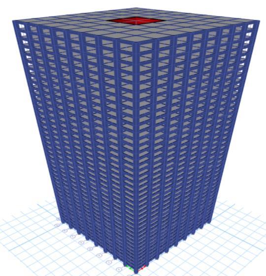
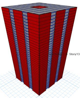
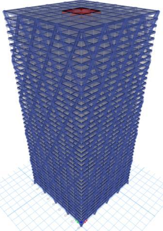
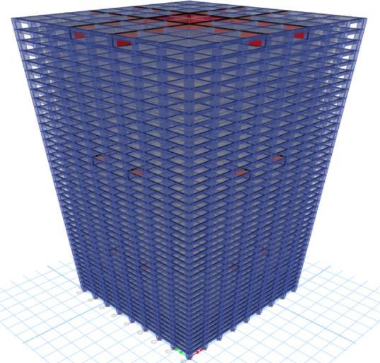
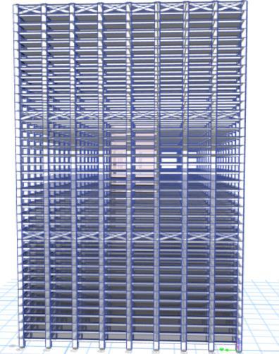
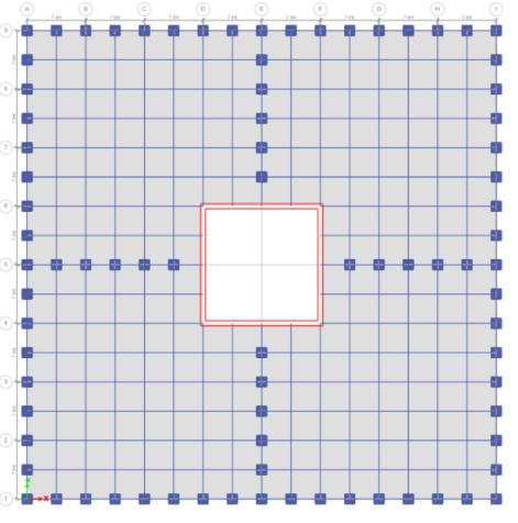
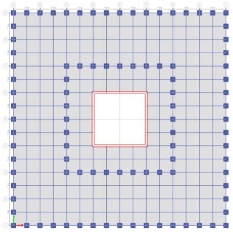
Seven 40-storey reinforced concrete high-rise building modelsweredevelopedrepresentingdifferentlateralloadresistingsystems:
International
Volume: 13 Issue: 01 | Jan 2026 www.irjet.net
Building Dimensions:
•TotalHeight:140m(40storeys)
•StoreyHeight:3.5m
•PlanDimension:56m×56m(square)
•BayWidth:5m
Material Properties and Sections
ConcreteandSteelProperties:
•GradeofConcrete:M40,M55
•CompressiveStrengthofConcrete:40,55N/mm²
•ModulusofElasticity(Concrete):31,622N/mm²
•GradeofSteel(Reinforcement):Fe550
•RebarStrength:550N/mm²
SectionDimensions(Commonforallsystems):
•Beam:600mm×900mm(RectangularRCCsection)
•Column:1200mm×1200mm(RectangularRCCsection)
•Slab:150mmthickness
•Core(Centralshearwall):600mmthickness
SpecialElements:
•Diagrid(DG):CHS1000×40mm
•Outrigger(OT):600mmthicknesswall
•BeltTrussSystem(BTS):RHS600×1000×30mm
Loading Conditions
GravityLoads(asperIS875-1987PartI&II):
•SuperImposedDeadLoad:1.5kN/m²
•LiveLoad:4.0kN/m²
•MassSource:100%deadload+50%liveload
SeismicLoadParameters(asperIS1893-2016):
•SeismicZone:ZoneV
•ZoneFactor(Z):0.36
•SoilType:SoftSoil
•ImportanceFactor(I):1.2
•ResponseReductionFactor(R):5
•DampingRatio:5%
WindLoadParameters(asperIS875-1987PartIII):
•WindSpeed:50m/sec
•RiskCoefficient(K₁):1.0
•TerrainRoughness:Category4
•TopographyFactor(K₃):1.0
•ImportanceFactor:1.0
Earthquake Records for Time History Analysis
Table-2: Earthquake Record S.
International Research Journal of Engineering and Technology (IRJET) e-ISSN: 2395-0056
Volume: 13 Issue: 01 | Jan 2026 www.irjet.net p-ISSN: 2395-0072
3. RESULTS AND DISCUSSION
3.1 Modal Analysis
Table-3: MODE 1 TIME PERIOD OF ALL STRUCTURES
S. No. Model Computed Period







Chart -1:Modaltimeperiodofallstructure
Volume: 13 Issue: 01 | Jan 2026 www.irjet.net
3.2 Base Shear from Time History Analysis
Table-4:
Modal Analysis
MRFexhibitsmaximumflexibility(2.645speriod)requiring 6-7modesfor90%masscapture,whileSW-MRFismoststiff (2.086s period) achieving efficiency at mode 5, with IS 1893:2016 empirical formula systematically underestimatingdynamicflexibilityacrossallsystems.
International Research Journal of Engineering and Technology (IRJET) e-ISSN: 2395-0056
Volume: 13 Issue: 01 | Jan 2026 www.irjet.net p-ISSN: 2395-0072
Base Shear Response
Time history analysis reveals base shear substantially exceeds equivalent static values, with MRF experiencing lowest demand (90,000-5,55,000kN) and Tube-inTube/Bundled Tube systems attracting maximum forces (1,80,000–16,90,000kN),validatingthenecessityofmultirecordanalysisoversingle-earthquakeassessment.
Lateral Displacement
Spectral period compatibility governs displacement response more than peak ground acceleration, with Northridge inducing maximum displacement (700–1760 mm) and flexible systems (MRF, BTS) showing inherently higher displacements due to longer natural periods comparedtostiffersystems(SW-MRF,DiagridandTube-inTube).
Drift Ratio and Damage Control
Northridgeproduceshighestdriftratios(0.006–0.016),with Moment resisting frame (0.01582) achieving poorest performanceandSW-MRF,Diagrid,outriggerandTube-inTubedeliveringbestcontrol(0.00675,0.00828,0.00999and 0.01082),representingfrom30%-57%reductionrelativeto MRF.
System Ranking & Performance
Tube-in-Tube achieves optimal balance establishing definitiverankingas TT > SW-MRF > DG > OT > BT > BTS > MRF, confirming that structural system configuration governsseismicperformancemorecriticallythanmember strength and distributed lateral load paths deliver most resilientperformance.
[1] M. M. Ali and K. S. Moon, "Advances in Structural SystemsforTallBuildings:EmergingDevelopmentsfor ContemporaryUrbanGiants," Buildings,vol.8,no.8,p. 104,Aug.2018,doi:10.3390/buildings8080104.
[2] B. H. Naik and B. S. Suresh Chandra, "Comparative Analysis between Tube in Tube Structure and ConventionalMomentResistingFrame," Int. Res. J. Eng. Technol. (IRJET),vol.4,no.10,pp.807-812,Oct.2017.
[3] D. Wu, T. Y. Yang, Y. Xiong, and S. Tesfamariam, "Experimental assessment on aseismic capacity of a perimeterdiagridconcretecorestructure:Shaketable tests," Measurement, vol. 203, p. 111925, 2022, doi: 10.1016/j.measurement.2022.111925.
[5] H. Singh, A. K. Tiwary, S. Thakur, and G. Thakur, "Performance evaluation of high-rise reinforced concretebuildingsunderdynamicloadingconsidering different structural systems," Mater. Today Proc., vol. 103, pp. 176-182, 2024, doi: 10.1016/j.matpr.2023.08.251.
[6] A.Khanorkar, S. Sukhdeve, S. V. Denge, and S. P. Raut, "Outrigger and belt truss system for tall building to controldeflection:Areview," GRD J. - Global Res. Dev. J. Eng.,vol.1,no.6,pp.6-15,May2016
[7] K. Jani and P. V. Patel, "Analysis and design of diagrid structuralsystemforhighrisesteelbuildings," Procedia Eng., vol. 51, pp. 92-100, 2013, doi: 10.1016/j.proeng.2013.01.015.
[8] G.Lacidogna,"Tallbuildings:Secondaryeffectsonthe structuralbehavior," Proc. Inst. Civ. Eng. - Struct. Build., vol. 170, no. 6, pp. 391-405, Jun. 2017, doi: 10.1680/jstbu.16.00058.
[9] G. Lacidogna, D. Scaramozzino, and A. Carpinteri, "A matrix-based method for the structural analysis of diagrid systems," Eng. Struct., vol. 193, pp. 340-352, 2019,doi:10.1016/j.engstruct.2019.05.046.
[10] M. H. Gunel and H. E. Ilgin, "A proposal for the classification of structural systems of tall buildings," Build. Environ.,vol.42,no.7,pp.2667-2675,2007,doi: 10.1016/j.buildenv.2006.07.007.
[11] M.J.KumarandS.M.Gupta,"Comparativestudyoftime historyanalysisofoutriggerandtube-in-tubestructures usingETABS,"in Recent Trends inCivilEngineering,A.Sil et al., Eds. Singapore: Springer Nature Singapore Pte Ltd.,2023,pp.357-370,doi:10.1007/978-981-19-40552_29
[12] E. Mele, M. Toreno, G. Brandonisio, and A. De Luca, "Diagridstructuresfortallbuildings:Casestudiesand designconsiderations," Struct. Des. Tall Spec. Build.,vol. 23,no.2,pp.124-145,2014,doi:10.1002/tal.1029.
[4] H. A. Elgohary, "A comprehensive review and ANN analysis of empirical formulae for determining the fundamentalperiodofmulti-storyRCmomentresisting frames," J. Umm Al-Qura Univ. Eng. Archit.,vol.16,no.1, pp.1519-1526,2025,doi:10.1007/s43995-025-001923.