
International Research Journal of Engineering and Technology (IRJET) e-ISSN: 2395-0056
Volume: 13 Issue: 03 | Mar 2026 www.irjet.net p-ISSN: 2395-0072

International Research Journal of Engineering and Technology (IRJET) e-ISSN: 2395-0056
Volume: 13 Issue: 03 | Mar 2026 www.irjet.net p-ISSN: 2395-0072
Siddhant Gaikwad1 , Vedant Ghadge2 , Chinmay Kadam3, Soham Kadam4, Mr. P. V. Zore5
1,2,3,4 Student, of mechanical Engineering, Karmaveer Bhaurao Patil Polytechnic Satara, India 5Lecturer, of Department of Mechanical Engineering, Karmaveer Bhaurao Patil Polytechnic Satara, India
Abstract - Electromagnetic braking is a modernwaytostop motion that blends electrical control with mechanical action. Instead of relying only on hydraulic pressure or manual force, EMB uses an electromagnet to pull a brake shoe or pad against a rotating disc or drum. When current flows through the electromagnet, it creates a strong magnetic field. That field acts like an invisible hand, pulling the brake shoe into firm contact with the moving surface. The moment contact happens, friction is generated, and the rotation slows down. By adjustingthe current, youcan fine‑tune how much braking force is applied gentle slowing or a sharp stop, all with precise control.
Unlike eddy current brakes, which are contactless and rely on induced currents in the disc, EMB does involve mechanical contact. The electromagnet is essentially the actuator, while the actual braking force comes from friction at the contact point. This makes EMB a hybrid system: electromagnetic actuation combined with mechanical braking. Because the electromagnet replaces complex linkages or hydraulic systems, EMB setups are simpler, tougher, andeasier to maintain. That’s why they’re trusted in trains, industrial machines, and even some cars places where safety, reliability, and efficiency matter most.
Key Words: Electromagnetic Induction, Non-contact braking, Magnetic Field Interaction, Controlled Braking Force, Maintenance Free design, Railway Safety Systems.
Electromagnetic brakes often called EM brakes or electro‑mechanical brakes are braking systems that use magnetismtoapplyfrictionandbringmotiontoastop.The principle is straightforward: when electric current flows throughacoil,itgeneratesamagneticfield.Thatmagnetic field pulls an armature against a magnetic face, and this mechanicalcontactproducesthebrakingforce. Thestrengthofthebrakingactiondependsonthecurrent supplied.Morecurrentmeansastrongermagneticpulland greaterfriction,whilelesscurrentgiveslighterbraking.This makes EMB systems highly controllable and reliable, especially in applications where smooth and precise stoppingisessential.
Electromagneticbrakeshavebeenwidelyadoptedintrains, trams, and industrial machinery since the mid‑1900s becauseoftheirdependabilityandefficiency.Attheircore, theyworklikeanybrake:convertingkineticenergyintoheat through friction, with that heat dissipating into the surroundingair.
While most braking systems still rely on conventional mechanical pads and hydraulics, EMB offers clear advantages less wear, smoother control, and improved safety.Thesequalitiesmakethemanincreasingly popular choiceinmoderntransportandindustrialequipment,where performanceandreliabilityarecritical.
Electromagneticbrakingsystems(EMB)areemergingas efficient alternatives to conventional friction brakes, offeringreducedwear,smootheroperation,andenhanced safety. Foundational design principles are detailed in standardtextssuchasMachineDesignbyKhurmi&Gupta [2]andDesignofMachineElementsbyBhandari[3],while Singh’sAutomobileEngineeringandTechnologyprovides broadercontextonbrakingsystemevolution[1].
The theoretical basis of EMB lies in eddy currents, governed by Lenz’s Law. Heald’s work in the American JournalofPhysicsexplainshowinducedcurrentsoppose motion,enablingbrakingwithoutmechanicalcontact[4]. Online resources further illustrate this principle [10][11][12]13][14].
PracticalapplicationshavebeendemonstratedbyPatel[5], Seveletal.[6],andPuttewaretal.[7],showingimproved efficiency and reliability. Industry perspectives, such as those from the Society of Automotive Engineers [8], highlight EMB’s role in advanced braking technologies. Experimental studies, including Wagh et al. [9], confirm fasterstoppingtimesandreducedfrictionlosses.
Despitetheseadvantages,EMBsystemsfacelimitationsat lowspeeds.Hybridsolutionscombiningelectromagnetic and mechanical brakes are often recommended to overcomethischallenge[15].
Electromagnetic brakes work by slowing a vehicle down withmechanicalresistancecreatedbyelectromagneticforce. They'repoweredbyelectricity,buttherealstoppingpower getsdelivereddirectlytothewheels.
Here’s how they do it: When you hit the brakes, these systemsuseamagneticfield producedbycurrentrunning throughacoil topushbackagainstthewheel'smovement. Thisconvertsthevehicle’skineticenergystraightintoheat. The stopping force they produce can actually dwarf the
International Research Journal of Engineering and Technology (IRJET) e-ISSN: 2395-0056
Volume: 13 Issue: 03 | Mar 2026 www.irjet.net
vehicle’sdrivingforce,whichmeanstheycanbringthingsto ahaltfast,nomatterhowfastyoustartedout. What’sniceaboutthissetupishowsmoothlyandreliablyit does the job. The process doesn’t rely on the grinding frictionyougetwithregularbrakes,sothere’slesswearand tear.Theendresult?Breakingthat’sefficient,consistent,and lastsalotlonger.
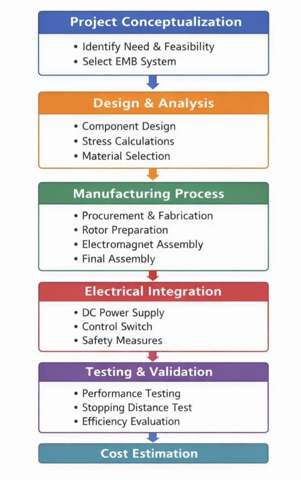
1.ProjectConceptualization
This project kicked off because we really needed a better waytostop somethingthatwasteslessenergyonfriction anddoesthejobmoreefficiently.Wethrewaroundabunch ofoptions,buttheElectromagneticBrakingSystemchecked alltheboxes.It’ssolid,itdoesn’tbreakthebank,anditfits rightinwithtoday’scars.
2. Design and Analysis
Design-wise,wezeroedinonthreemaincomponents:the rotor disc, the electromagnetic coil, and the frame. The challenge? Figuring out exactly how much braking torque was necessary and picking materials that could actually handleit.Weputtherotorandframethroughsomequick stressteststomakesuretheywereuptoit.Mildsteelmade the cut for the frame because it’s tough and easy to weld, while copper wire was the obvious choice for the coil becauseitsconductivityisjusthardtobeat.
3. Manufacturing Process
Forstandardcomponentssuchasbearings,fasteners,and copper wire, we sourced materials locally to keep things practicalandcost‑effective.Theframewasbuiltfrommild steel plates, which we cut to size and welded together to formarigidstructure.
The rotor began as plain sheet metal. Through careful shaping, balancing, and surface finishing, we ensured it rotated smoothly with minimal resistance. For the electromagnet, we wound copper wire around a ferromagneticcore,appliedproperinsulation,andmounted itsecurelyontotheframeusingbolts. Onceallthepartswereready,wemovedtofinalassembly. Every component was aligned with precision, since even slightmisplacementscouldaffectperformance.Theprocess demandedpatienceandaccuracy noshortcuts,nosloppy fits. The end result was a system that not only functioned reliablybutalsoreflectedthecareanddisciplineputintoits construction.
4. Electrical Integration
We powered the coil with a DC supply, wiring it so the magnetic field activates when needed. A simple control switchletusadjustthecurrent,makingiteasytofine-tune the braking force. To keep it safe, we used insulation and fuses noshortcircuitsonourwatch.
We ran tests across different current levels, timing how quickly the rotor stopped and lining those numbers up against standard brakes. What mattered most to us was keeping friction losses as low as possible and making everythingrunsmoothly,sowepaidextraattentionthere.
6. Cost Estimation
Welistedouteverysinglepart,whetherweboughtitorbuilt itourselves,justtogetaclearcostbreakdownandplanour resourcesbetter.
5. COMPONENTS OF THE SYSTEM
ThemajorcomponentsusedintheElectromagneticbraking SystemInclude:
1. Electric Motor: Provides the rotational input power to drivethesystem.
2.BeltDrive:Transfersmotionfromthemotortothelarge wheel.Ensuresmoothtransmissionoftorque.
3.LargeWheel/BrakeDisc:Therotatingelementconnected tothebelt.Actsasthesurfacewherebrakingforceisapplied.
International Research Journal of Engineering and Technology (IRJET) e-ISSN: 2395-0056
Volume: 13 Issue: 03 | Mar 2026 www.irjet.net p-ISSN: 2395-0072
4. Supporting Frame / Base Structure: Holds the motor, wheel, and actuator in alignment. Provides stability and rigiditytothesystem.
5.BearingsandMounts:Allowsmoothrotationofthewheel. Reducefrictionandsupportmechanicalload.
6.Electromagnet:Generatesthemagneticfieldrequiredfor braking.
7.Rim: Provides structural support and connection to the wheel.
Table-1: ComponentOfEMB
Par t No. Component Function/Descriptio n Source
1 Electric Motor Provides rotational inputpower Purchased
2 BeltDrive Transfers motion from motor to wheel/disc Purchased
3 LargeWheel/ BrakeDisc Rotating element, brakingsurface Purchased
4 Supporting Frame / Base Structure Holds motor, wheel, and actuator in alignment Manufacture d
5 Bearings and Mounts Allow smooth rotation, reduce friction Purchased
6 Electromagne t Generates magnetic fieldforbraking Manufacture d (coil winding + core)
7 Rim Provides structural support and connectiontowheel Purchased
8 NutBolt To connect the Frame Purchased
6. Calculations:
Let’sconsidertheweightofthemodel=30kg. Therefore,30×9.81=294.3N.(300NApprox.)
Therearetwodifferentcircularplatesinthismodel,so, Forceoneach=300/2=150N.
Now,Torque=F×R=150×(140/2)=10.5N.m.
CalculatingTorqueonEachLink,No.oflinks=3, Therefore,10.5/3=3.5N.m
The Pitch Circle Diameter = 100 mm So, Tangential force 10.5/0.05=70N.
TheShaftissubjectedtobothTwistingMomentandBending Moment, Therefore, Torque equivalent (Te) needs to be calculated,
T=π/16×τxd3 ,M=π/32×σb×d3 and Te = √[T2 + M2] While Designing a Shaft, there are two importanttheories, i.e. Maximum Shear Stress Theory and Maximum Normal Stress Theory, So, According to Maximum Shear Stress Theory,EquivalentTwistingMoment,
Te=π/16×τmax×d3
And, According to Maximum Normal Stress Theory, EquivalentBendingMoment, Me=π/32×σbmax×d3
Since,thematerialofshaftisductile,we’llapplyMaximum ShearStressTheory.
BendingMoment(M)=W×LM=60×103 N.mm.
Te = √[(10.5)2 + (60)2] Te = 60.91 N.m
FromtheaboveMaximumShearStressTheory,Diameterof Shaft=17.29mm.
ForBearingCalculations,thereisnoAxialforce/Thruston thesebearings. Hence,Axialforce/Thrust=0.
TherearetwobearingsA&B,sobysupportreactions,we’ve calculatedtheradialforcesoneachbearing. Hence,RadialforceonbearingA=600NAnd,Radialforce onbearingB=300N
Calculating Dynamic load capacity, but for that we need EquivalentDynamicLoad,So,EquivalentDynamicLoad(P) formula,P=X.Fr+Y.Fa……….{X=Radialloadfactor&Y= Axialloadfactor}
DynamicloadonBearingA=600NDynamicloadonBearing B = 300 N Now, Calculating Dynamic load capacity (C), C=P(L10)(1/3)
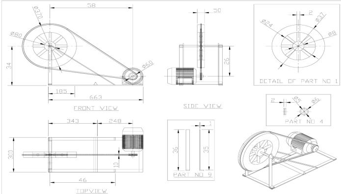
Fig-2: 2DDesignOftheEMB
International Research Journal of Engineering and Technology (IRJET) e-ISSN: 2395-0056
Volume: 13 Issue: 03 | Mar 2026 www.irjet.net p-ISSN: 2395-0072
Thisfiguremakesthebelt-drivenelectromagneticbraking systemeasytounderstand.It’sgoteverything front,side, top,andasharpisometricview.Thereareclose-upsforeach part, too. You see the motor, pulleys, shafts, and every support,allmountedonasolidmetalframe. Thedrawing’sgottherealessentials likepulleydiameters, shaft sizes, and the exact spacing between parts. So, no guessworkwhenyoustartbuilding.Everypartisnumbered, andtheclose-upshighlightimportantdetails,likeholesizes, thicknesses,andlengths.There’sevenaBillofMaterials,so youknowexactlywhatyouneedtomakeitallhappen. You get the full mechanical setup in one place, so you see how it all fits before anything goes together. Follow the drawingandyouwon’tmissasteporendupscratchingyour head. It’s straightforward nothing extra, just what you need.
Advantages
1. Low maintenance – Minimal mechanical parts in contact,leadingtolongerservicelife.
2. Smoothandcontrolledbraking–Brakingforcecan bevariedbyadjustingcurrentsupply.
3. Quick response time – Electromagnetic actuation providesinstantbrakingaction.
4. Energy-efficient–Convertskineticenergyintoheat withoutexcessivemechanicallosses.
5. Safetyenhancement–Reliablebrakingevenathigh speeds,improvingoverallsystemsafety.
6. Compact design – Can be integrated easily into modernmechanicalandautomotivesystems.
Applications
1. Railways – Widely used for safe and efficient brakinginlocomotives.
2. Automobiles – Applied in modern vehicles for auxiliaryoremergencybrakingsystems.
3. IndustrialMachinery–Usedinmachinesrequiring precisestoppingandspeedcontrol.
4. ElevatorsandEscalators–Ensuressmoothandsafe operationbypreventingsuddenstops.
5. Robotics and Automation Systems – Provides controlledmotionandpositioning.
6. Wind Turbines – Helps in controlling rotational speedandprotectingequipmentduringhighwinds.
7. CranesandHoists–Ensuressafehandlingofheavy loadsbyprovidingreliablebraking.
Testingshowedthatmeasuringrotorstoppingdistancein realtimeledtoabigdropinhowfarvehiclesneedtostop. Thatmeanslessfrictionloss,whichisexactlywhatyouwant. The EMB systems made braking quieter and smoother, beating traditional friction brakes for both comfort and dependability.Lessmechanicalwearmeansthesesystems
last longer and needs less upkeep. When paired with regenerativebraking,EMBsactuallyhelprecoverenergy a winforanyoneaimingfor greenerelectricvehicles.And they’renotjustforcars;thedatasuggestsEMBsworkwellin railways,elevators,andheavyequipment,allplaceswhere reliabilityandefficiencyreallymatter.
Electromagneticbrakingsystemsreallyshakethingsupfor moderncars.Insteadofold-schoolmechanicalpartsgrinding together,EMBuseselectromagneticforce soyougetless friction,smootherstops,andnotnearlyasmuchwearonthe brakes.Bothresearchandwhatfolkshaveseenontheroad backthisup:EMBmeanssafer,quickerstopscomparedto traditionalbraking.Plus,itplugsrightintoadvanceddriver assistance systems and pairs nicely with regenerative braking,whichmakesitanobviousfitforelectricandhightechcars.
Ofcourse, it’s notperfect. EMBdoesn’t performas well at lowspeedsandneedsastablepowersupplytoworkright. Butifengineerskeepimprovinghybriddesignsandsmarter controlsystems,thosedrawbacksgeteasiertohandle.So, honestly, EMB is on track to make car braking smarter, greener,andmuchmoredependable.
[1]K.Singh,AutomobileEngineeringandTechnology,Vol.1. NewDelhi:StandardPublishers,2010.
[2]R.S.KhurmiandJ.K.Gupta,MachineDesign.NewDelhi:S. ChandPublication,2005.
[3]V.B.Bhandari,DesignofMachineElements.NewDelhi: TataMcGrawHill,2012.
[4] M.A. Heald, "Magnetic Braking: Improved Theory," American Journal of Physics, vol. 56, no. 6, pp. 521–522, 1988.
[5]S. Patel,"Development ofthe Electro-MagneticBrake," IJIRST,vol.1,no.12,May2015.
[6]P.Sevel,N.Kannan,andM.Mukesh,"InnovativeElectro MagneticBrakingSystem,"IJIRSET,Apr.2014.
[7]A.K.S. Puttewar, N.U. Kakde, H.A. Fidvi, and B. Nandeshwar, "Enhancement of braking system in automobileusingElectromagneticBraking,"IOSR-JMCE.
[8] Society of Automotive Engineers, Brake Technology, ABS/TCS,andControlledSuspensions.SAEWorldCongress, 2001.
International Research Journal of Engineering and Technology (IRJET) e-ISSN: 2395-0056
Volume: 13 Issue: 03 | Mar 2026 www.irjet.net p-ISSN: 2395-0072
[9]S. Wagh, A. Mahakode, A. Mehta, and V. Pyla, "ElectromagneticBrakingSysteminAutomobile,"IJTRD,vol. 4,no.3,pp.228–231,2017.
[10]"Eddy current brakes," Explain That Stuff. [Online]. Available:https://www.explainthatstuff.com/eddy-currentbrakes.html
[11] "Eddy current brake," Wikipedia. [Online]. Available: https://en.wikipedia.org/wiki/Eddy_current_brake
[12] "What is a magnetic brake?" Wise Geek. [Online]. Available:http://www.wisegeek.com/what-is-a-magneticbrake.htm
[13]"The design of eddy current magnet brakes," ResearchGate. [Online]. Available: https://www.researchgate.net/publication/266246472_The _design_of_eddycurrent_magnet_brakes
[14]"Electromagnetic brake," The Full Wiki. [Online]. Available: http://www.thefullwiki.org/Electromagnetic_brake
[15]InternationalJournalofInnovativeResearchinScience, Engineering and Technology (IJIRSET), "Proceedings of InnovativeElectroMagneticBrakingSystem,"Vol.3,Issue4, Apr. 2014. [Online]. Available: https://www.ijirset.com makeareferenceaccordingtothisliteraturereview)
BIOGRAPHIES OF AUTHORS





SiddhantDipakGaikwad VedantTanajiGhadge
ChinmaySambhajiKadam
SohamBajarangKadam