
International Research Journal of Engineering and Technology (IRJET) e-ISSN: 2395-0056
Volume: 13 Issue: 03 | Mar 2026 www.irjet.net p-ISSN: 2395-0072
International Research Journal of Engineering and Technology (IRJET) e-ISSN: 2395-0056
Volume: 13 Issue: 03 | Mar 2026 www.irjet.net p-ISSN: 2395-0072
Pradeep. S1 , Nikitha. S2 , Shivani. S3 , Mamatha. T4 , Charan. N5 , Mr.Ramesh Babu. S6
1,2,3,4,5 B.Tech Students, Department of Electrical and Electronics Engineering
6 Assistant Professor, Department of Electrical and Electronics Engineering Nalla Malla Reddy Engineering College , Hyderabad, India***
Abstract - – Uncompensatedreactivepower inlow-voltage residential distribution networks contributes to elevated feeder I²R losses, reduced line capacity, and degraded voltage regulation issues that become increasingly significant as residential load density grows. While distributed Automatic Power Factor Correction (APFC) systems offer a practical solution, existingprototypestypicallyrelyonpre-programmed or manually calibrated capacitor values, limiting their accessibility and accuracy in practical non-technical deployments. This paper presents thedesignandexperimental validation of a low-cost, IoT-enabled residential APFC prototype utilizing an ESP32 microcontroller, a PZEM-004T v4.0 energy monitoring module, anda six-step relay-switched capacitor bank rated at 440 V AC. A key contribution of the proposed system is an automated capacitor characterization mode that measures and stores each capacitor's actual reactive power contribution under live supply conditions, eliminating manual calibration and enabling consumerfriendlyplug-and-play operation. Real-time IoT monitoringis implemented via MQTT communication through the HiveMQ cloudbroker, with electricalparametersdisplayedlocallyona 20×4 LCD and remotely via the Electrical Parameter Monitor (EPM) mobile application developed on the MIT App Inventor platform. Experimental validation under resistive and inductive load conditions confirmed correct compensation logic andeffectivestepwise power factor improvement.Under an R-L test load, the system improved power factor from 0.71 to 0.97, reduced reactive power demand from 141 VAR to 29 VAR, and achieved an estimated 46.4% reduction in feeder resistive losses with experimental results closely corroborating theoretical predictions. The proposed system demonstrates the viability of self-calibrating, IoT-integrated distributed APFC for smart grid and Advanced Metering Infrastructure compatible residential applications.
Key Words: Automatic Power Factor Correction; Reactive Power Compensation; ESP32; Internet of Things; Smart Grid; MQTT.
Reactive power compensation is critical for maintaining voltage stability and minimizing I²R losses in low-voltage residential distribution networks. While individual householdreactivedemand ismodest,itsaggregate effect acrossfeedersandsubstationsissubstantial contributing
to elevated conductor losses, reduced line capacity, and accelerated equipment aging [1], [3]. Centralized compensation via substation capacitor banks addresses broadvoltageregulationbutlacksthegranularitytorespond tolocalizedorrapidlyvaryingreactivedemandsintroduced by modern distributed energy resources (DERs) and dynamicloadprofiles[2],[4].
Distributed Automatic Power Factor Correction (APFC) systems deployed at the load level offer a practical alternative by compensating reactive power at its source throughrelay-switchedcapacitorbankscontrolledbylowcostmicrocontrollers[5].Concurrently,InternetofThings (IoT) integration via lightweight MQTT messaging over cloudbrokerssuchasHiveMQenablesreal-timemonitoring of electrical parameters, providing both utilities and consumers with actionable grid data [2], [6]. Although inverter-based distributed energy resources can provide dynamicreactivesupport,relay-switchedcapacitorsolutions remain more cost-effective and universally deployable acrossdiverseresidentialsettings[7].
Thispaperpresentsthedesignandexperimentalvalidation ofanIoT-enabledresidentialAPFCprototypeusingaPZEM004T energy measurement module, an ESP32 microcontroller, and a six-step relay-controlled capacitor bank. The system incorporates real-time MQTT communication via HiveMQ, a 20×4 LCD display for local feedback, and a custom mobile application for remote monitoring. Experimental results confirm effective power factor improvement from 0.71 to 0.97 under inductive loading,demonstratingtheviabilityofdistributedload-level compensationforresidentialsmartgridapplications.
A.Distributed vs. Centralized Reactive Power Compensation
Reactive power management is fundamental to voltage stability, loss minimization, and asset utilization in distributionnetworks[1],[3].Centralizedcompensation typically via substation capacitor banks or voltage regulators addresses broad voltage regulation but is increasingly insufficient for modern grids with dynamic loads and high distributed energy resource (DER) penetration [2]. Such schemes lack the granularity to
International Research Journal of Engineering and Technology (IRJET) e-ISSN: 2395-0056
Volume: 13 Issue: 03 | Mar 2026 www.irjet.net p-ISSN: 2395-0072
respondrapidlytolocalizedreactivedemandfluctuations, particularly over long low-voltage feeders where reactive powertransmitspoorly[3],[5].
Distributed APFC systems overcome these limitations by deploying small compensators close to end-use loads, operatingautonomouslythroughrelay-switchedcapacitor bankscontrolledbymicrocontrollerssuchastheESP32[5].
Analytical models confirm that distributed control outperforms centralized methods in radial residential networks, achieving superior feeder loss reduction, improvedbusvoltageprofiles,andgreaterscalability[1],[4].
Although individual residential reactive demands are modest, their cumulative effect across feeders and substationsissignificant upto70%oftotalsystemlosses occurwithindistributionnetworks,withapproximately13% ofdeliveredenergydissipatedasheatfromuncompensated reactive currents [3], [4]. Coordinated deployment of distributed APFC at neighborhood scale can substantially reduce feeder loading, free line capacity, and extend transformerlifespanthroughreducedthermalstress[4],[5].
The proliferation of IoT and Advanced Metering Infrastructure (AMI) technologies has enabled real-time acquisition and wireless communication of key electrical parameters using lightweight publish-subscribe protocols such as MQTT over cloud brokers like HiveMQ [2], [6]. IntegratingIoTmonitoringwithAPFChardware combining PZEM-004Tmeasurementmodules,ESP32microcontrollers, and mobile application interfaces provides utilities with granular grid visibility and empowers consumers with actionablepowerqualitydata[6].
Inverter-basedDERsofferfastdynamicreactivesupportbut remainconstrainedbycostandregulatorybarriers;relayswitched capacitor banks are therefore more universally applicable for residential compensation [7]. Despite demonstratedtechnical and economicbenefits,significant gapsremain:large-scalefieldvalidationofaggregatedfeeder impactsisscarce;optimalcoordinationbetweendistributed controllersandexistingAMIinfrastructurerequiresfurther study; and cybersecurity implications of pervasive IoT deployment in distribution systems have not been fully addressed.Thepresentwork contributestowardbridging thefirstgapthroughexperimentalprototypevalidation.
A.System
The proposed system performs real-time reactive power compensation at the residential load level and enables remote monitoring through wireless communication. As showninFig.1,thearchitectureintegratesfive functional units:electricalparametermeasurement,centralprocessing and control, capacitor switching, user interface, and IoT communication.TheESP32DevKitV1servesasthecentral processing unit, executing the compensation algorithm, managing relayswitching,storingcalibrationdata innonvolatile memory, and handling Wi-Fi-based MQTT communication.
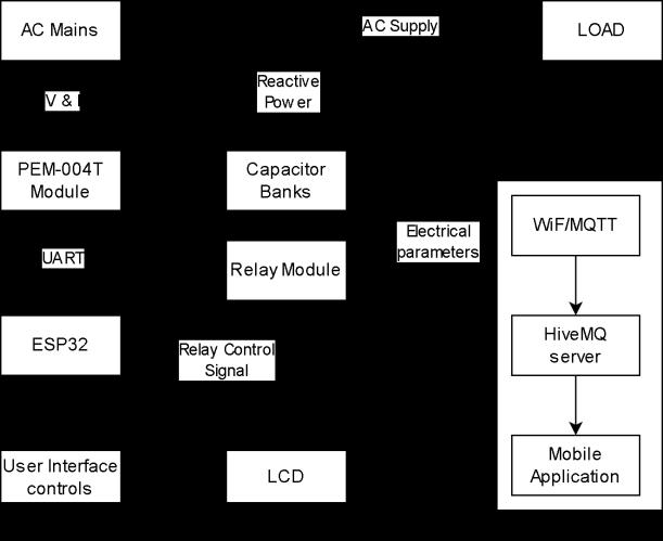
1. Block diagram of the proposed IoT-enabled APFC system.
ElectricalparametersaremeasuredusingaPZEM-004Tv4.0 energymonitoringmodulecoupledwitha100Asolid-core current transformer (2000:1 ratio), providing galvanic isolation between the high-voltage AC line and the lowvoltagecontrolcircuitry.ThemoduledirectlycomputesRMS voltage, RMS current, active power, reactive power, and powerfactor,transmittingallvaluestotheESP32viaUART serialcommunicationforuseasinputstothecompensation algorithm.
Reactivepowercompensationisimplementedusingasixstepcapacitorbank(R1=5.0µF,R2–R4=2.5µFeach,R5–R6=1.5µFeach),witheachcapacitorindividuallycontrolled by a relay module rated at 10 A / 250 VAC. The reactive powersuppliedbyeachcapacitorisgivenbyQc=V²·2πf·C, where V is RMS voltage, f is supply frequency, and C is capacitance. A 30 A load relay provides isolation during calibration, and a 120 kΩ discharge resistor across each
International Research Journal of Engineering and Technology (IRJET) e-ISSN: 2395-0056
Volume: 13 Issue: 03 | Mar 2026 www.irjet.net p-ISSN: 2395-0072
capacitor ensures safe charge dissipation upon disconnection.
The control flowchart is presented in Fig. 2. The ESP32 continuouslyacquireselectricalparametersandevaluates thepowerfactoragainstathresholdof0.95.Ifcompensation is required, the controller calculates the reactive demand deficit and selects the capacitor step whose stored VAR contributionisclosesttotherequiredcompensation.After each switching action, parameters are re-evaluated to confirm adequate correction. Overcompensation is preventedbyverifyingthatactivatingthenextstepwould notresultinaleadingpowerfactorcondition.Adedicated capacitorcharacterizationmodeindividuallyenergizeseach capacitor, measures its actual reactive contribution, and storesthevalueinnon-volatilememorycompensatingfor manufacturingtolerancesandsupplyvoltagevariations.
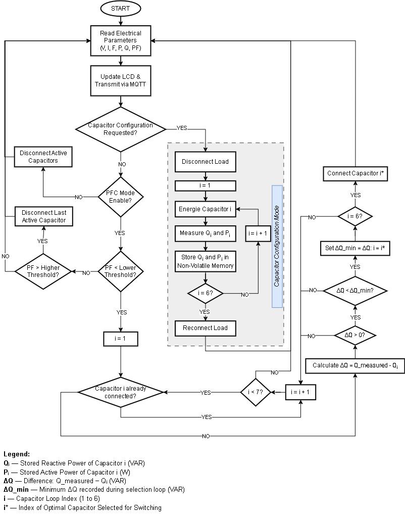
2. Flowchart of the proposed APFC control algorithm.
E. User Interface and IoT Communication
A 20×4 LCD with PCF8574 I²C interface displays continuously updated system measurements including voltage,current,activepower,reactivepower,powerfactor, andactivecapacitorsteps.Threepushbuttonsprovidemenu navigation and calibration mode access; a toggle switch enables manual activation or deactivation of the PFC
mechanism. For wireless communication, the ESP32 connectstotheHiveMQMQTTbrokerviaitsinternalWi-Fi module, publishing measured electrical parameters to a dedicated topic. A custom mobile application developed usingMITAppInventorsubscribestothistopicandpresents real-timemonitoringdatatotheenduser.
A.Single-PhasePowerRelations
For a single-phase load operating at RMS voltage V and drawingRMScurrentIatphaseangleφbetweenvoltageand current,thethreepowerquantitiesaredefinedas:
S = V·I(1)
P = S·cosφ (2)
Q = S·sinφ (3)
where S=apparentpower(VA), P=activepower(W), Q= reactivepower(VAR), φ=phaseangle.
Powerfactorisexpressedas:
PF = cosφ = P/S (4)
Reactivepowermayalsobewrittenintermsofactivepower andpowerfactorangleas:
Q = P·tanφ (5)
B. Required Reactive Compensation
ToimprovepowerfactorfromaninitialvaluePF₁=cosφ₁to a target value PF₂ = cosφ₂, the required compensating reactivepowerΔQcis:
ΔQc = P(tanφ₁−tanφ₂) (6)
whereP=activepowerofload(W),φ₁=initialPFangle,φ₂ =targetPFangle.
Fortheexperimentaltestcase,withP=350W,PF₁=0.71 (φ₁=44.8°),andtargetPF₂=0.95(φ₂=18.2°),substituting into(6):
ΔQc = 350×(tan44.8°−tan18.2°) ≈ 144VAR..(7)
C. Capacitor Sizing
Thereactivepowersuppliedbyashuntcapacitorconnected acrossasingle-phasesupplyis:
Qc = V²·2πf·C(8)
where V = RMS supply voltage (V), f = supply frequency (Hz), C=capacitance(F).
International Research Journal of Engineering and Technology (IRJET) e-ISSN: 2395-0056
Volume: 13 Issue: 03 | Mar 2026 www.irjet.net p-ISSN: 2395-0072
Rearrangingtoobtaintherequiredcapacitanceforaknown compensationtarget:
C = ΔQc/(2πf·V²) (9)
At V = 254.5 V and f = 50 Hz, the ideal per-step capacitor reactivecontributionscomputedfrom(8)are:R1(5.0µF)≈ 101.4VAR;R2–R4(2.5µFeach)≈50.7VAR;R5–R6(1.5µF each) ≈ 30.4 VAR. These values are stored in non-volatile memoryduringthecapacitorcharacterizationmodeforuse duringreal-timeswitchingdecisions.
D. Line Current Reduction
ForafixedactivepowerloadP,linecurrentbeforeandafter compensationis:
I₁ = P/(V·PF₁) I₂ = P/(V·PF₂) (10)
SincePF₂>PF₁,itfollowsthatI₂<I₁.Theratioofcurrentsis:
I₂/I₁=PF₁/PF₂=cosφ₁/cosφ₂ (11)
For the experimental case (PF₁ = 0.71, PF₂ = 0.97), the currentratiofrom(11)is0.71/0.97≈0.732representinga 26.8%reductioninlinecurrentaftercompensation.
E. Distribution Line Loss Reduction
Resistivedistributionlossesareproportionaltothesquare oflinecurrent.ForafeederofresistanceR:
Pₗ₀ₛₛ = I²·R (12)
Thepercentagereductioninfeederlossesachievedbypower factorimprovementistherefore:
LossReduction(%) = [1−(PF₁/PF₂)²]×100...(13)
Substituting the experimental values into (13): Loss Reduction=[1−(0.71/0.97)²]×100≈46.4%.Thisconfirms thatdistributedload-levelcompensationyieldssubstantial reductions in feeder I²R losses, validating the system’s contributiontoresidentialgridefficiencyimprovement.
V.EXPERIMENTAL SETUP
TABLE I. Experimental Components and Specifications
Component Model / Specification Qty.
Microcontroller ESP32 DevKit V1, 240 MHz,Wi-Fi 1
EnergyMonitor PZEM-004Tv4.0,100A 1
Current Transformer Solid-core, non-contact (bundledwithPZEM) 1
4-CH Relay Module 10A/250VAC 1
2-CH Relay Module 10A/250VAC 1
Load Isolation Relay Single-channel, 30 A / 250VAC 1
Capacitors 2.5 µF, 440 V AC, MPP type 5
Capacitors 1.5 µF, 440 V AC, MPP type 2
LCDDisplay 20×4, with PCF8574 I²C interface 1
DCPowerSupply AC-DCadapter,5V/2A 1
UserInterface 3× push buttons, 1× toggleswitch,zeroPCB 1 Isolation Switches Rockerswitches(supply, load,capacitorbank) 3 RLoad Incandescent filament bulb,100W/230V 1 R-LLoad 100Wfilamentbulb+43 W fluorescent choke ballast(parallel) 1
The prototype was assembled on a 6 mm plywood board housing all components in a compact, accessible layout. Threerockerswitchesprovideindependentisolationofthe AC supply, load, and capacitor bank, allowing safe connection and disconnection of each subsystem during testingwithoutdisturbingtheremainingcircuitry.A5V/2 ADCadaptersuppliespowertotheESP32,relaymodules, LCD, and PZEM-004T logic circuitry. The experimental prototypeisshowninFig.3.
International Research Journal of Engineering and Technology (IRJET) e-ISSN: 2395-0056
Volume: 13 Issue: 03 | Mar 2026 www.irjet.net p-ISSN: 2395-0072
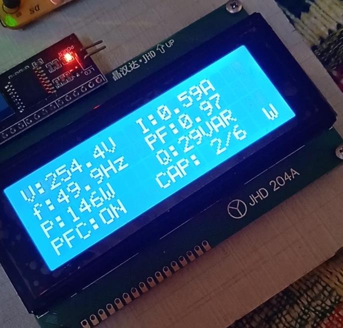
Twoloadconfigurationsweretested.Fortheresistiveload test, a single 100 W incandescent filament bulb was connected,representinganear-unitypowerfactorbaseline condition(PF≈0.99–1.00)withnoreactivedemand.Forthe inductive load test, the same 100 W filament bulb was connectedinparallelwitha43Wfluorescentchokeballast, producing a combined R-L load with a measured initial power factor of approximately 0.71 and a reactive power demand of approximately 141 VAR representative of a typicalresidentialinductiveloadscenario.
C. Experimental Procedure
Prior to testing, capacitor characterization mode was activatedbytogglingthedesignatedswitch.Eachcapacitor wasindividuallyenergized,itsactualreactivecontribution measuredbythePZEM-004Tmodule,andthevaluestoredin ESP32 non-volatile memory to account for component tolerances. During live testing, the system continuously acquiredelectricalparametersviaUART,displayedreal-time readings on the LCD, and executed the compensation algorithmautonomously.IoTfunctionalitywasverifiedby confirmingliveparameterupdatesontheMITAppInventor mobile application subscribed to the designated HiveMQ brokertopic.Allmeasurementswererecordeddirectlyfrom theLCDdisplayandthemobileapplicationinterface.
A. Resistive Load Test
TableIIpresentsthemeasuredelectricalparametersunder thepurelyresistiveloadcondition.Thesystemrecordeda powerfactorof0.99–1.00withanegligiblereactivepowerof approximately 5 VAR consistent with the near-unity powerfactorcharacteristicofanincandescentfilamentload.
Thecontrolalgorithmcorrectlyidentifiedthisconditionas requiring no compensation and maintained all capacitor relays in the OFF state throughout the test. This confirms that the decision logic operates correctly under noninductive conditions, preventing unnecessary reactive injection that would otherwise lead to a leading power factor.
TABLE II. Measured Parameters
Current(A)
A
Power(W) 100W
ReactivePower(VAR) ≈5VAR
PowerFactor 0.99–1.00
CapacitorStepsActive 0(allrelaysOFF)
B. R-L Load Stepwise Compensation
Table III presents the experimental readings recorded duringstepwisecapacitoractivationundertheR-Lload.At baseline (Step 0), the system measured a power factor of 0.71withareactivepowerdemandof141VAR,confirming theneedforcompensation.Upondetectionofthiscondition, the controller activated the first capacitor step (5.0 µF two 2.5 µF capacitors in parallel via the 2-channel relay module),reducingreactivepowerfrom141VARto62VAR and improving power factor to 0.90. A second step (additional2.5µFvia the4-channel relaymodule)further reducedreactivepowerto29VAR,achievingafinalpower factorof0.97.
The controller correctly terminated switching at Step 2 verifying that the overcompensation prevention logic functioned as intended. Activating the next available step would have injected approximately 50 VAR into a system withonly29VARremainingreactivedemand,resultingina leadingpowerfactorcondition.Thisdemonstrateseffective real-timedecision-makingunderpracticalinductiveloading.
TABLE III. Stepwise Compensation Results R-L Load Ste p Capacito r Config. V (V) PF Q (VAR ) Controller Action
0 No caps (baseline ) 254. 5 0.7 1 141 Compensatio ntriggered
1
2
Volume: 13 Issue: 03 | Mar 2026 www.irjet.net
C. Theoretical vs. Experimental Comparison
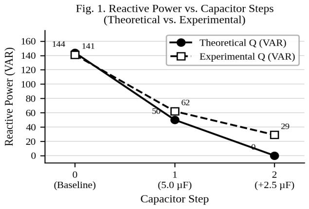
TableIVandFigs.1–2comparethetheoreticalcompensation values derived in Section IV with experimental measurements. At baseline, theoretical and experimental reactivepowervaluesdifferbyonly2.1%(144VARvs.141 VAR), confirming the accuracy of the mathematical model under the given load conditions. At Step 1, a deviation of approximately24%isobservedinreactivepower(50VAR theoreticalvs.62VARexperimental),attributedprimarilyto capacitormanufacturingtolerance(±5–10%),relaycontact resistance,wiringimpedance,andsupplyvoltagefluctuation duringswitching.Correspondingly,theexperimentalpower factor at Step 1 (0.90) is lower than the theoretical prediction(0.99).AtStep2,theexperimentalpowerfactorof 0.97 closely approaches the theoretical near-unity value, confirming that cumulative compensation performance convergestowardthepredictedbehavior.
TABLE IV. Theoretical vs. Experimental Comparison
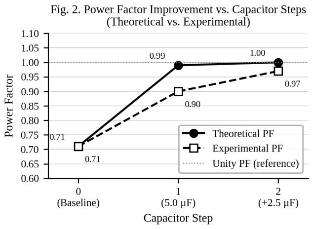
Theexperimentalresultsconfirmthreekeycontributionsof theproposedsystem.First,theAPFCprototypesuccessfully performedautonomousreactivepowercompensationunder practical inductive loading, improving power factor from 0.71 to 0.97 a 36.6% improvement and reducing reactivepowerdemandfrom141VARto29VAR.Applying equation (13) from Section IV, this corresponds to an estimated46.4%reductioninfeederI²R losses,validating thesystem'scontributiontoresidentialdistributionnetwork efficiency.
Second, unlike conventional APFC prototypes that rely on pre-programmed or manually measured capacitor values, theproposedsystemincorporatesanautomatedcapacitor characterization mode that measures and stores each capacitor's actual reactive contribution under live supply conditions eliminatingmanualcalibrationandenhancing consumer-side usability without requiring technical expertise. The accuracy of the compensation steps, which closely follow theoretical predictions, demonstrates the effectivenessofthisself-characterizationapproach.
Third, real-time IoT monitoring was successfully demonstrated via MQTT communication through the HiveMQbroker,withliveelectricalparametersconfirmedon theMITAppInventormobileapplication.Thisvalidatesthe system's compatibility with smart grid and AMI infrastructure requirements. The observed deviations between theoretical and experimental values within acceptable engineering tolerances are consistent with practicalfactorsincludingcapacitoraging,relayswitching characteristics, and measurement uncertainty inherent to thePZEM-004Tmodule(ratedaccuracy±1%).
This paper presented the design and experimental validationofalow-cost,IoT-enabledresidentialAutomatic
International Research Journal of Engineering and Technology (IRJET) e-ISSN: 2395-0056
Volume: 13 Issue: 03 | Mar 2026 www.irjet.net p-ISSN: 2395-0072
PowerFactorCorrection(APFC)systemutilizinganESP32 microcontroller,PZEM-004Tenergymonitoringmodule,and a six-step relay-switched capacitor bank. The system successfully demonstrated autonomous reactive power compensationunderpracticalinductiveloadingconditions, withexperimentalresultscloselycorroboratingtheoretical predictions derived from the mathematical model. A key distinguishingcontributionoftheproposedprototypeisits automatedcapacitorcharacterizationmode,whichmeasures and stores each capacitor's actual reactive contribution under live supply conditions eliminating manual calibrationandmakingthesystemgenuinelyaccessibleto non-technical residential users without any firmware modification.
Experimental validation confirmed a power factor improvement from 0.71 to 0.97, a reduction in reactive powerdemandfrom141VARto29VAR,andanestimated 46.4% reduction in feeder I²R losses demonstrating meaningfulpotentialforimprovingresidentialdistribution networkefficiencyatscale.Real-timeIoTmonitoringviathe Electrical Parameter Monitor (EPM) mobile application furthervalidatedthesystem'scompatibilitywithsmartgrid andAdvancedMeteringInfrastructurerequirements.Future workwillfocusonmulti-unitcoordinationacrossresidential feeders,integrationwithexistingsmartmeterinfrastructure, and evaluation under varying supply conditions and harmonic-rich load environments to assess scalability towardneighborhood-leveldeployment.
[1] A.Á.Téllez,G.López,I.Isaac,andJ.González,"Optimal Reactive Power Compensation in Electrical Distribution SystemswithDistributedResources:Review,"Heliyon,vol. 4,no.8,p.e00759,Aug.2018.
[2] D.StanelytėandV.Radziukynas,"ReviewofVoltageand ReactivePowerControlAlgorithmsinElectricalDistribution Networks,"Energies,vol.12,no.24,p.4789,Dec.2019.
[3] O. Candra, K. Hartmann, and N. Manthey, "Optimal DistributionGridAllocationofReactivePowerwithaFocus ontheParticleSwarmOptimizationTechniqueandVoltage Stability," Scientific Reports, vol. 14, no. 1, p. 10023, May 2024.
[4] T.Nguyen,A.Ngo,andL.Nguyen,"AnEffectiveReactive PowerCompensationMethodandaModernMetaheuristic Algorithm for Loss Reduction in Distribution Power Networks,"Complexity,vol.2021,ArticleID6643210,Oct. 2021.
[5] S. Bolognani and S. Zampieri, "A Distributed Control Strategy for Reactive Power Compensation in Smart
Microgrids," IEEE Transactions on Automatic Control, vol. 58,no.11,pp.2818–2833,Nov.2013.
[6] M.Korchak,B.Savchyn,andO.Karpenko,"VirtualSource of Reactive Power in Electricity Supply Systems of Household Consumers," Energy Engineering and Control Systems,vol.5,no.1,pp.19–25,Jan.2019.
[7] M.Sarkar,J.Meegahapola,andM.Datta,"ReactivePower ManagementinRenewableRichPowerGrids:AReviewof Grid-Codes, Renewable Generators, Support Devices and Optimization Algorithms," IEEE Access, vol. 6, pp. 41458–41489,May2018.