
International Research Journal of Engineering and Technology (IRJET) e-ISSN: 2395-0056
Volume: 13 Issue: 03 | Mar 2026 www.irjet.net p-ISSN: 2395-0072

International Research Journal of Engineering and Technology (IRJET) e-ISSN: 2395-0056
Volume: 13 Issue: 03 | Mar 2026 www.irjet.net p-ISSN: 2395-0072
Tammana Sai Srinivas, Sathya Gayathry Pippalla , V. Samitinjaya
Aeronautical Engineering Institute of Aeronautical Engineering India
Aeronautical Engineering Institute of Aeronautical Engineering India
Aeronautical Engineering Institute of Aeronautical Engineering India
ABSTRACT- This paper presents the modelling and comparative structural analysis of a fixed-wing unmanned aerial vehicle (UAV) wing using a classical NACA 4412 airfoil. A three-dimensional wing geometry is developed and analysed under equivalent aerodynamic loading using finite element analysis. The structural response of different composite materials, including CFRP–Epoxy, CFRP–PEEK, Kevlar/Epoxy, and selected GFRP systems, is evaluated in terms of von Mises stress and total deformation. The results are compared using graphical and regression-based statistical methods to identify trends in material behaviour under identical loading conditions. The objective of this research is to gain insight into the effect of material stiffness and density on the wing structure of a UAV.
The research work is focused on the structural performance of a fixed-wing UAV designed with the NACA 4412 airfoil, and the impact of various composite materials on stress and displacement.
Keywords - UAV wing, NACA 4412, finite element analysis, composite materials, equivalent aerodynamic loading, regressionanaly
Unmanned aerial vehicles (UAVs) are essential tools for various tasks like surveillance, remote sensing, environmental monitoring, topographical mapping, and scientific research. These tasks need airframes that offer high aerodynamic efficiency and strong structure while staying lightweight. This helps maximize endurance, payload capacity, and overall efficiency.Amongthedifferentpartsofanairframe,thewingplaysakeyroleastheliftingsurface.Italsofacessignificant aerodynamic,inertial,andmaneuverloads.Forthisreason,designingwingsthatarebothlightandstructurallyefficientis crucial in UAV development. Modern UAVs often use carbon fiber reinforced polymers (CFRP), glass fiber reinforced polymers(GFRP),andaramidfiberreinforcedpolymers(AFRP).Thesematerialsarefavoredfortheirexcellentstrengthto-weightratio,highstiffness,resistancetocorrosion,anddurabilityagainstfatigue.Additionally,theuniquepropertiesof compositematerialsallowforcustomizeddesigns.Engineerscanorientfibersspecificallybasedontheloadingconditions and stiffness needs, making them ideal for aerospace. Among the various airfoil shapes for fixed-wing UAVs, the NACA 4412 airfoil has been thoroughly studied and validated for low-speed flight. Its moderate camber and thickness offer effective lift, a gradual stall, and sufficient internal space for structural components like spars and ribs. Thus, understanding the structural performance of UAV wings made from different composite materials under aerodynamic loads is vital during the initial design stage. This understanding assists in selecting suitable materials and developing efficient,sustainablewingdesignsforUAVs.
CarbonFiberReinforcedPolymer(CFRP)iswidelyusedindesigninghigh-performanceUAVwingstructures.Itsexcellent specific strength and stiffness are crucial for reducing the weight of the structure while maintaining its aerodynamic shape. In this research, CFRP is considered one of the main materials for the NACA 4412 wing, particularly for loadbearingpartslikewingskinsandspars.Carbonfibershaveahighelasticmodulus,whichgivesthemstrongresistanceto spanwise bending and torsion from aerodynamic lift forces and maneuvering. The high stiffness of carbon fibers works well for the NACA 4412 airfoil section. This airfoil features a cambered surface that generates a higher lift coefficient at lowanglesofattack,whichincreasesthebendingmomentalongthewingspan.Additionally,thelowdensityofCFRPhelps reducethewing'sweight,improvingtheUAV'senduranceandpayloadcapacity.TheanisotropicnatureofCFRPallowsfor thefiberstobeorientedinlinewiththemainstressesofthewingstructure.However,thebrittlefailuremodeofCFRPand itshighercostcomparedtoothermaterialsarefactorstoconsiderduringtheinitialdesignphase.TheNACA4412airfoil was chosen for buckling analysis because its higher camber results in a more accurate aerodynamic loading distribution
International Research Journal of Engineering and Technology (IRJET) e-ISSN: 2395-0056
Volume: 13 Issue: 03 | Mar 2026 www.irjet.net p-ISSN: 2395-0072
and structural response for UAV wings. The NACA 4412 has realistic lift characteristics, making it suitable for structural analysisunderaerodynamicloads.
GlassFiberReinforcedPolymer(GFRP)iscommonlyusedinUAVwingsasaneconomicalsubstituteforCFRP,whichhas relativelygoodstrength,longevity,andresistancetoimpact.Inthisresearch,GFRPisconsideredasasubstitutematerial fortheNACA4412wingdesignwiththesamegeometricandloadingrequirements.
GFRPhaslowerrigiditythanCFRP,whichtranslatestohigherelasticdeflectionwhensubjectedtoaerodynamicloading.In thecaseoftheNACA4412airfoil,thiscanresultinhigherwingdeflectionandbetterresistancetodamage.GFRPismore applicabletosecondarystructuralcomponentslikeribs,controlsurfaces,andwingskinsoflow-costUAVs.
Another advantage of GFRP is its electrical insulation characteristic, which is advantageous for UAV wings containing antennasandavionicsystems
Optimizationofstructureandmaterialisaverysignificantareafortheimprovementofunmannedaerialvehicles(UAVs) performance and reliability, particularly considering the stringent weight constraints and loading conditions. In this context, Aswin Kumar et al. (2021) performed an in-depth analysis on the structural optimization of a multi-rotor UAV structure using computational structural analysis techniques. The authors employed finite element analysis (FEA) to examine the stress response, deformation, and factor of safety of the structure subjected to loading conditions. The authorsdemonstratedthattopologyandsizeoptimizationtechniquescouldresultinasignificantweightreductionofthe structure without compromising its strength and stiffness properties. The findings of the authors revealed that computational structural analysis is an effective approach for optimizing the strength-weight ratio of UAV structures, therebyincreasingthepayloadcapacityandefficiencyofflight.
The application of composite materials in the design of UAV wings has been widely researched due to the superior mechanical properties ofcompositematerials.Aresearchpapertitled “Structural AnalysisofUAV WingsDesigned Using Composite Materials” was published in the International Journal for Research in Applied Science & Engineering Technology(IJRASET).Theresearchpapercomparedtheuseofcompositematerialswiththeconventionaluseofmetallic materialsinthe design ofUAVwings. The researchpaper appliedfinite elementanalysistoinvestigatethestress,strain, anddeformationcharacteristicsofcompositematerialssubjectedtoaerodynamicloads.Theresultsoftheresearchpaper validated that composite materials possess the ability to reduce weight by a substantial amount with high stiffness and strength. Theresearchpaperalsovalidated thatcomposite materialspossess betterfatiguelifeanddampingcoefficients thanmetallicmaterials.
Agoodtheoreticalknowledgeofmaterialpropertiesisnecessaryfortheeffectiveanalysisofresultsofstructuralanalysis. Callister and Rethwisch, in their book "Materials Science and Engineering: An Introduction," have provided a theoretical backgroundfortheunderstandingofmechanicalpropertiesofmaterialssuchaselasticity,plasticity,fracture,andfatigue. The book describes stress-strain relationships, anisotropic properties of composites, and failure theories of structural materials. These topics assume importance in the context of UAV structures, which are prone to cyclic loading, bending, and torsion. The book is an important reference for material selection and for matching simulation results with actual materialproperties,thusenhancingthetheoreticalbackgroundofcomputationalstructuralanalysis.
Further details on the design of a UAV wing were obtained through the analysis and design of a VTOL UAV wing using finite element analysis, which was published in the STTKD journal. The paper sought to assess the design of a wing intendedforverticaltake-offandlandingmissions,whichentailcomplicatedloadingconditions.TheauthorsappliedFEA todeterminestressconcentration,deformation,andsafetyfactorsresultingfromaerodynamicandthrustloads.Thepaper demonstratedthatFEAisapplicableindeterminingstressconcentrationfactorsandthesafetyofthestructurepriortothe developmentoftheprototype.Thepaperemphasizedthesignificanceofcomputationalanalysisinreducingdevelopment time and costs while ensuring the reliability of the structure in the design of a UAV win
International Research Journal of Engineering and Technology (IRJET) e-ISSN: 2395-0056
Volume: 13 Issue: 03 | Mar 2026 www.irjet.net p-ISSN: 2395-0072
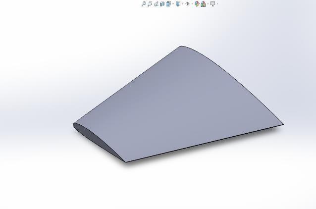
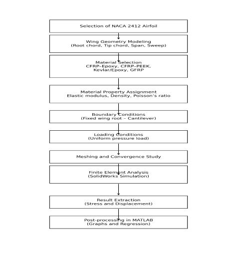
ThegeometricmodellingoftheUAVwingwasdoneusingthetraditionalNACA4412airfoilsection,whichhasbeenwidely adopted in low-speed fixed-wing UAV designs because of its desirable lift properties and simplicity of design. The twodimensional airfoil points were created and loaded into the CAD system to develop the initial airfoil shape. A threedimensionalwingshapewasthencreatedbyspecifyingessentialdesignvariableslikerootchordlength,tipchordlength, total wingspan, and angle of sweep, thus simulating a practical tapered wing design. Wingspan = 450mm , Root chord = 180mm,TipChord=120mm,TaperRatio=0.667
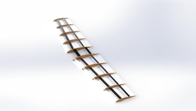
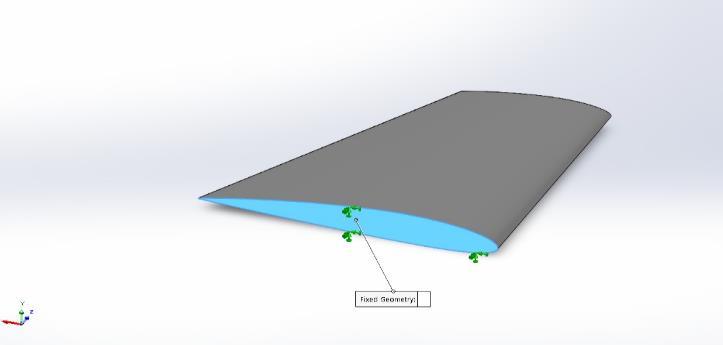
Theairfoilshapewasthenextrudedandloftedtocreateasmooththree-dimensionalwingsurface.Thewingwasassumed to be a cantilever wing, with the assumption that the root section is fixed to the fuselage and the tip section is free. This assumption is a practical simulation of the actual wing boundary condition experienced during UAV flight. The resulting geometry was then validated for continuity and accuracy before being imported into the finite element analysis environment.
In order to assess the effect of material properties on the structural behaviour of the UAV wing, a number of composite materialsystemsthatarewidelyusedinaerospaceengineeringhavebeenchosenforcomparison.TheseareCarbonFiber Reinforced Polymer (CFRP) with an epoxy matrix, CFRP with a PEEK thermoplastic matrix, Kevlar/Epoxy, and various formsofGlassFiberReinforcedPolymer(GFRP).
In order to maintain a level of consistency and facilitate a fair comparison under the same loading and boundary conditions, all the materials were idealized as linear elastic isotropic materials. While it is true that composite materials areanisotropicinnature,thissimplificationenablesadirectcomparisonofthestructuralbehaviourofthematerialsbased ontheirelasticproperties.ThematerialpropertiesofYoung’smodulus,Poisson’sratio,density,andtensilestrengthwere chosenfromstandardliteratureandmaterialhandbooks.
International Research Journal of Engineering and Technology (IRJET) e-ISSN: 2395-0056
Realistic boundary conditions and loading configurations were also established. The wing root area was fully fixed, preventingalltranslationalandrotationaldegreesoffreedomtomodelacantileveredwingmountingonthefuselage.This boundaryconditionisimportanttoensurethatthewingresponseisdominatedbybendingandsheardeformationsalong thewingspan.
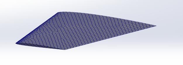
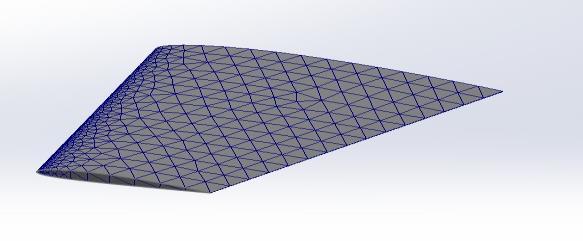
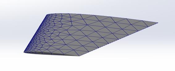
Meshconvergenceanalysisconfirmedthatthenumericalresultsareindependentofmeshsize,ensuringsolutionaccuracy. Buckling analysis was performed on a larger span wing to evaluate structural instability, where increased slenderness enhancessusceptibilitytobuckling.Theuseofdifferentairfoilgeometriesandscaleswasbasedonanalysisrequirements, balancingcomputationalefficiencyandrealisticstructuralbehavior.
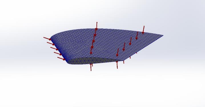
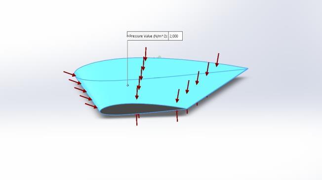
Aerodynamicloadingwasmodelledbyapplyinganequivalentuniformlydistributedpressureloadactingnormaltothe wingsurface.Thissimplifiedloadingmodelisadequatetomodeltheoveralleffectofliftforcesgeneratedduringsteadylevelflight,withoutrequiringcomplexfluid-structureinteractionorcomputationalfluiddynamics(CFD)simulations.The
Volume: 13 Issue: 03 | Mar 2026 www.irjet.net p-ISSN: 2395-0072 © 2026, IRJET | Impact Factor value: 8.315 | ISO 9001:2008 Certified Journal | Page2106
International Research Journal of Engineering and Technology (IRJET) e-ISSN: 2395-0056
applicationofthesamepressurevalueforallmaterialmodelsenabledadirectcomparisonofthestructuralresponses, independentofmaterialproperties.
CalculationofEquivalentAerodynamicPressure:
TheequivalentaerodynamicpressureappliedontheUAVwingiscalculatedusingthedynamicpressureequation:
q=(1/2)ρV²
where:
ρ=airdensity=1.225kg/m³(standardsea-levelcondition)
V=UAVflightvelocity
ForatypicalsmallUAV,acruisevelocityof55m/sisconsidered.
SubstitutionofValues
q=(1/2)×1.225×(55)²
q=0.6125×3025
q=1851N/m²
FinalAppliedPressure
The calculated dynamic pressure is approximately 1850 N/m², which is rounded off to 2000 N/m² for application in the structuralanalysis.
Volume: 13 Issue: 03 | Mar 2026 www.irjet.net p-ISSN: 2395-0072 © 2026, IRJET | Impact Factor value: 8.315 | ISO 9001:2008 Certified Journal | Page2107
International Research Journal of Engineering and Technology (IRJET) e-ISSN: 2395-0056
Volume: 13 Issue: 03 | Mar 2026 www.irjet.net p-ISSN: 2395-0072
Finite Element Analysis (FEA) was carried out using SolidWorks Simulation, a popular structural analysis software. The three-dimensional wing model was meshed with solid finite elements to accurately capture the wing geometry. A mesh refinementstudywascarriedouttoensuremeshconvergence,wherethemeshsizewasprogressivelydecreaseduntilthe differencesinstressanddisplacementvaluesbecameinconsequential.
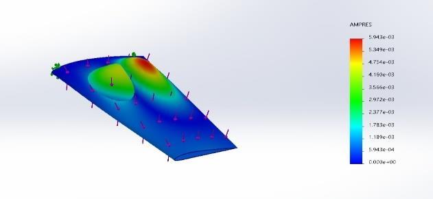
Foreachmaterialcombination,astaticstructuralanalysiswascarriedoutwiththesameboundaryconditionsandloading. The two key outputs obtained from the analysis included the maximum von Mises stress, which captures the stress condition of the wing, and the maximum resultant displacement (URES), which captures the stiffness and bending response of the wing. These outputs are extremely valuable in understanding the structural integrity and displacement responseoftheUAVwingforeachmaterialcombination.
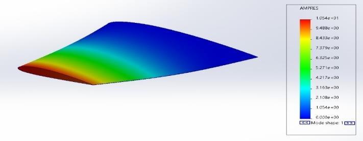
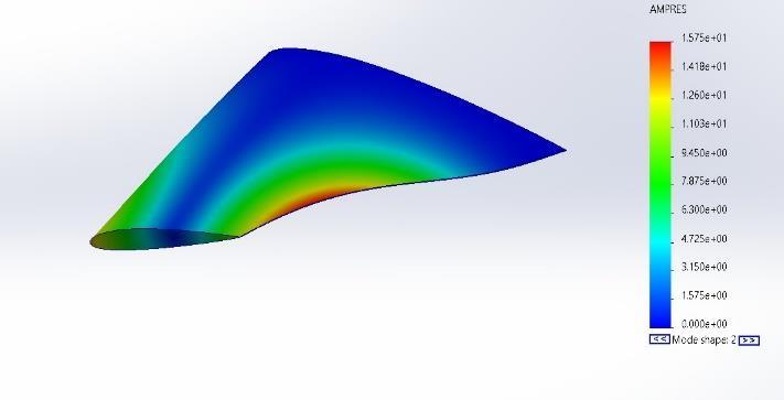
Thewingofafixed-wingUAVischeckedtoseehowithandlesmovementandifitisstrongenoughwhenitisvibrating.We useakindoftestcalledmodalanalysisonthewingtofindoutitsnaturalfrequenciesandmodeshapes.Thesethingsare really important to know so we can figure out if the wing will vibrate much when it is flying because of the air moving arounditortheengineshaking.WelookatmaterialslikeCFRP,GFRPandothertraditionalmaterialstoseehowtheyare differentintermsofstiffness,weightandhowtheymove.Theresultshelpusdecidewhichmaterialisbetter,athandling vibration having natural frequencies and being more stable. Modal analysis of the fixed-wing UAV wing really helps us makethewingdesignbettersoitworkswellissafeandlastsatimewhenitisbeingused.
International Research Journal of Engineering and Technology (IRJET) e-ISSN: 2395-0056
Volume: 13 Issue: 03 | Mar 2026 www.irjet.net
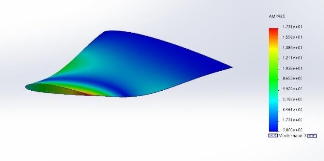
Fig 12: Mode3
Table 1:
TheUAVswinghaskindsof vibrations thathappen atdifferent natural frequencies.The first mode isthebendingmode, wherethewing bendsthe mostfromoneendtotheother. Thesecondmodeisthe twistingmode,wheretheUAVswing twists around its axis. The third mode is another bending mode. It happens at a higher frequency, which shows that the UAVs wing is very stiff. The fourth mode is the bending mode that happens along the chord direction, where the wing bends from front, to back. The fifth mode is another twisting mode. It is more complicated and happens at a higher order,whichshowsthattheUAVswingcantwistinmanydifferentways.
International Research Journal of Engineering and Technology (IRJET) e-ISSN: 2395-0056
Volume: 13 Issue: 03 | Mar 2026 www.irjet.net p-ISSN: 2395-0072
The response of the wing structure of the UAV was analyzed for the same loading and boundary conditions for various material systems to determine the effect of material properties on displacement and stress responses. The analysis was carried out mainly for maximum displacement and von Mises stress, as these values are essential indicators of stiffness and strength, respectively. The outcome of the study shows that the stiffness of the material, as indicated by the elastic modulus, is the major factor that determines the deformation of the wing, while the stress response is affected by the combined effect of stiffness, density, and material-related loading characteristics. Regression analysis was used to determinetheresponsebehaviorandensuretheconsistencyofthestructuralresponseofvariousmaterial
Theresultsofthemaximumdisplacementclearlyindicatethatthehighertheelasticmodulus,thelowerthedeformation forthesameloadingconditions.Thisobservationisinlinewiththeconventionalprinciplesofstructuralmechanics,which statethathigherstiffnessleadstogreaterresistancetobendingandlowerdeflection.TheCFRP-basedcompositematerial hadthelowestdisplacementamongthematerialsconsideredforanalysis,owingtoitshighestelasticmodulusandhighest stiffness-to-weight ratio. Kevlar and GFRP systems, on the other hand, had relatively higher displacement due to their relativelylowerstiffness.
Regressionanalysisbetweentheelasticmodulusandthemaximumdisplacementclearlyindicatedaninverserelationship between the two variables, which confirms that the deformation of the wing reduces systematically with an increase in stiffness.Theaimofthisregressionanalysisistodeterminethecharacteristicsofdeformationandalsotomakesurethat thebehaviorofthestructureisconsistentfordifferentmaterials.Thestrongcorrelationhasconfirmedthevalidityofthe finite element model and also ensured that the results are a true representation of the mechanical behavior of the wing structure.
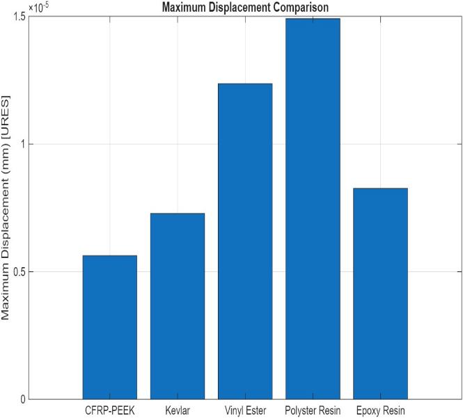
The graph compares the maximum displacement values of the UAV wing structure made of different material systems underthesameloadingandboundaryconditions.They-axisindicatesthemaximumdisplacementinmillimeters,andthe x-axisidentifiesthematerials,whichincludeEpoxy,CFRP-PEEK,Kevlar,VinylEster,PolyesterResin,andEpoxyResin.
From the graph, it is clear that CFRP-PEEK has a small displacement, which shows the advantage of carbon fiber reinforcement with a high-performance polymer matrix. Kevlar has a moderate displacement, which shows a balance betweenflexibilityandstiffness.
Incontrast, Vinyl Ester and Polyester Resin exhibitsignificantlyhigherdisplacementvalues,withPolyesterResinshowing the maximum deformation. Such a phenomenon can be ascribed to their relatively lower elastic modulus, which causes them to be less stiff and more prone to bending under the applied load. Epoxy Resin has an intermediate displacement response,whichisbetterthanthatofVinylEsterandPolyesterResinbutnotasgoodasthatofEpoxyorCFRPcomposites.
International Research Journal of Engineering and Technology (IRJET) e-ISSN: 2395-0056
Volume: 13 Issue: 03 | Mar 2026 www.irjet.net p-ISSN: 2395-0072
From the graph, it is evident that there is an inverse relationship between stiffness and maximum displacement. The materials with higher elastic modulus and superior reinforcement properties exhibit lower displacement, thus justifying theeffectofstiffnessinregulatingthedisplacementofthewing.
Table 2:
Thetableshowsthatallmaterialshavegoodstructuralperformanceintermsofsafetyand efficiency.However,extremely highFactorofSafety(FoS)indicatesthatallmaterialshavebeenoverdesigned,whichisnotgoodintermsofweight.The balancedFactorofSafetyisalsoevidentincompositematerials,whichhavehighspecificstrengthsandspecificstiffness
SpecificStrengthandSpecificStiffnessaresignificantparametersthatreflecttheefficiencyofmaterialsusedinaerospace applications.ThehighspecificStrengthandSpecificStiffnessofCFRP-PEEKconfirmthatitissuitableforlightweightUAV wingstructures.However,unlikeothercompositematerials,KevlarshowshighspecificStrengthbutlowspecificStiffness, whichindicateshighdeformability.Therefore,compositematerialshavehighspecificStrengthandspecificStiffnessthan neatresinmaterials.
TheresultofthevonMises stressanalysisisuseful inunderstandingthedistributionoftheinternal stressesin thewing structure. Unlike the displacement, the von Mises stress is not directly proportional to the elastic modulus. Rather, the stressisafunctionofthematerialstiffness,density,andresistancetotheinternalforces.Materialsthatarestiffer,suchas CFRP, have higher concentrations of stress, while materials that are less stiff, such as GFRP and Kevlar, have higher deformationareas.
However, the von Mises stress values for all the material systems remained within the permissible limits, thus ensuring that the wing structure meets the strength requirements under the applied loading conditions. The consistency in the stressdistributionsforallthematerial systemsfurthervalidatestheaccuracyofthefiniteelementanalysisandhencethe comparativestructuralanalysis.
International Research Journal of Engineering and Technology (IRJET) e-ISSN: 2395-0056
Volume: 13 Issue: 03 | Mar 2026 www.irjet.net p-ISSN: 2395-0072
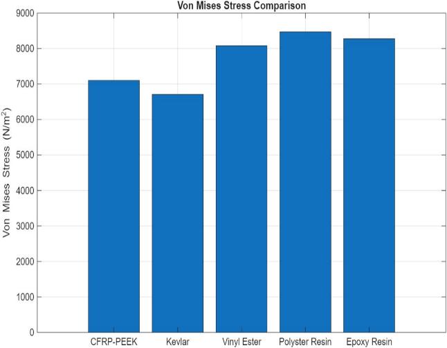
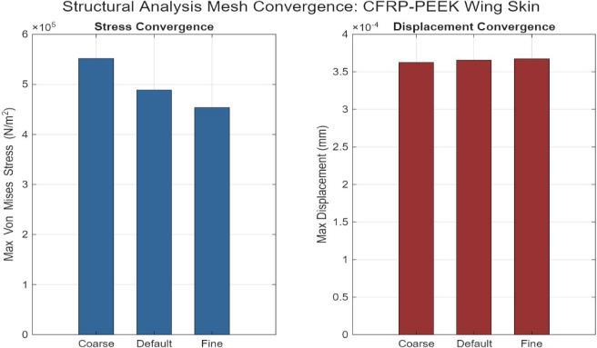
Fig 15: ComparisonofstressconvergenceandDisplacementconvergence
TheimagepresentsameshconvergencestudyforaCFRP-PEEKwingskin,illustratinghowtheresultsvarywithdifferent mesh densities coarse, default, and fine. In the stress convergence plot, the maximum von Mises stress decreases from approximately 5.5 × 10µ N/m² for the coarse mesh to about 4.5 × 10µ N/m² for the fine mesh, indicating that the coarse mesh tends to overestimate stress and that the solution stabilizes as the mesh is refined. In contrast, the displacement convergenceplotshowsaslightincreaseinmaximumdisplacementfromaround3.62×10⁻´mmto3.67×10⁻´mmasthe mesh becomes finer, with only minimal variation between the default and fine meshes. This behavior suggests that the displacement results are already close to convergence. Overall, the small changes observed between successive refinementsconfirmthattheanalysishasachievedmeshindependence,andthefinemeshprovidesthemostaccurateand reliablesolution.
ThisstudylooksatthedesignandanalysisofaUAVwing.Itisbasedonairfoilgeometryandusedfiniteelementmethods. Theresearcherscomparedmaterialstoseehowtheyhandledstress,deformationandefficiency.
Itwasfoundthatfiber-reinforcedcompositesaremuchbetterthanresinmaterialswhenitcomestostrengthandstiffness.
The UAV wing was analyzed to see how it would behave under conditions. The natural frequencies of the UAV wing are highenoughthatresonanceisnotaproblemwhentheUAVisbeingusednormally. Ameshconvergencewasalsocarried out.
AbucklinganalysisonanUAVwingandfoundthatitcanbeunstableifitistoolongandthin.Thismeansthatthewingcan deform,awayfromthepartthatisattachedtotheUAV.
International Research Journal of Engineering and Technology (IRJET) e-ISSN: 2395-0056
Volume: 13 Issue: 03 | Mar 2026 www.irjet.net p-ISSN: 2395-0072
So this study shows that the materials used the design of the UAV wing and the methods used to test it are all very important.Theyallplayarole,inmakingaUAVwingthat'slightweightandstrong.Thestudyhighlightstheimportanceof UAVwingdesigns.
Futureworkcanfocusonincorporatingmorerealisticstructuralandloadingconditionstofurtherenhancetheaccuracyof the analysis. This includes performing fatigue analysis under cyclic loading to estimate the service life of the wing, and dynamicloadingstudiestosimulaterealflightconditionssuchasgustloads.
The current model assumes an equivalent homogeneous material; future studies can implement detailed composite laminatemodelingtocaptureanisotropicbehaviormoreaccurately.
Solidmodelingwasusedforsimplicity,whileshellmodelingcanprovidemoreaccuratethin-structurebehaviorandcanbe exploredinfuturework.
Additionally,thestructuralanalysiscanbeextendedtoafullwingmodelincludingribsandsparstobetterrepresentreal aircraft structures. Localized reinforcement strategies at critical regions such as the wing root can also be explored to improvestructuralperformance.
AdvancedstudiessuchasnonlinearandaeroelasticanalysiscanfurtherimprovetheunderstandingofUAVwingbehavior underrealisticoperatingconditions.
1. Structural Optimization of Frame of the Multi-Rotor Unmanned Aerial Vehicle through Computational Structural AnalysisTocitethisarticle:VAswinKumaretal2021J.Phys.:Conf.Ser.1849012004
2.International Journal for ResearchinAppliedScience & Engineering Technology (IJRASET)ISSN:2321-9653; IC Value: 45.98;SJImpactFactor:7.538Volume14IssueIJan2026
3. Materials Science and Engineering AN INTRODUCTION WILLIAM D. CALLISTER, JR. Department of Metallurgical Engineering The University of Utah DAVID G. RETHWISCH Department of Chemical and Biochemical Engineering The UniversityofIowa
4.AnalysisanddesignofVTOLUAVwingusingfiniteelementanalysis
5.AerodynamicdesignandstructuraloptimizationofawingforanUnmannedAerialVehicle(UAV)
6.DesignandOptimizationofWingStructureforaFixed-WingUnmannedAerialVehicle(UAV)
7.Design,StructuralAnalysisandModalAnalysisofaWingSectioninanUAV
8. Structural Optimization of Frame of the Multi-Rotor Unmanned Aerial Vehicle through Computational Structural Analysis
9.ValidationofUAVWingStructuralModelforFiniteElementAnalysis