
International Research Journal of Engineering and Technology (IRJET) e-ISSN: 2395-0056
Volume: 12 Issue: 03 | Mar 2025 www.irjet.net p-ISSN: 2395-0072
International Research Journal of Engineering and Technology (IRJET) e-ISSN: 2395-0056
Volume: 12 Issue: 03 | Mar 2025 www.irjet.net p-ISSN: 2395-0072
Rahul P. Shekokar1 , Krunal M. Patel2 ,
1Engineer, Indo German Tool Room, Ahmedabad
2PG Student, Indo German Tool Room, Ahmedabad
Abstract - This paper presents the designandanalysisofan automatic indexing drill jig for lap joint flanges (ANSI B16.5). The jig enhances efficiency by allowing multiple hole sizes to be drilled on a single setup, reducing part rejections and production time. Designed in SolidWorks and analyzed using ANSYS 2022 R1, the study evaluates the jig’s structural performance, focusing on stress and deformation in the clamping system. The results confirm the jig's effectiveness in improving accuracy, minimizing setup changes, and optimizing manufacturing costs.
Key Words: Drill Jig, ANSI B16.5, ASTM A105, Finite Element Analysis, Machining, Structural Analysis
1.INTRODUCTION
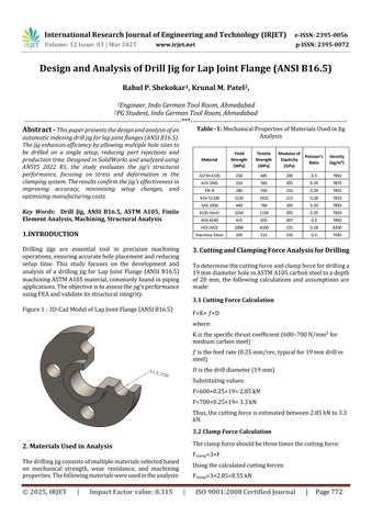
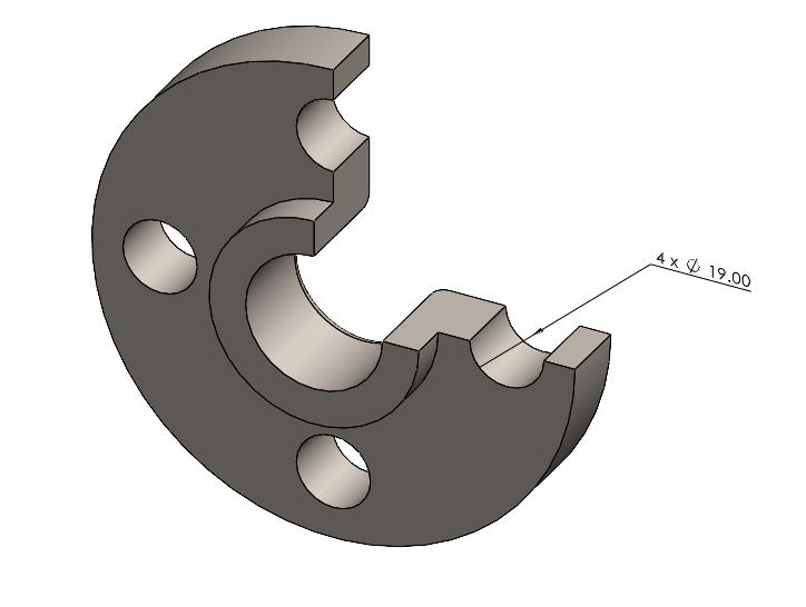
Drilling jigs are essential tool in precision machining operations,ensuringaccurateholeplacementandreducing setup time. This study focuses on the development and analysis of a drilling jig for Lap Joint Flange (ANSI B16.5) machiningASTMA105material,commonlyfoundinpiping applications.Theobjectiveistoassessthejig'sperformance usingFEAandvalidateitsstructuralintegrity.
Thedrillingjigconsistsofmultiplematerialsselectedbased on mechanical strength, wear resistance, and machining properties.Thefollowingmaterialswereusedintheanalysis:
Table -1: MechanicalPropertiesofMaterialsUsedinJig Analysis
Todeterminethecuttingforceandclampforcefordrillinga 19mmdiameterholeinASTMA105carbonsteeltoadepth of 20 mm, the following calculations and assumptions are made:
F=K×��×D
where:
Kisthespecificthrustcoefficient(600–700N/mm²for mediumcarbonsteel)
��isthefeedrate(0.25mm/rev,typicalfor19mmdrillin steel)
��isthedrilldiameter(19mm)
Substitutingvalues:
F=600×0.25×19=2.85kN
F=700×0.25×19=3.3kN
Thus,thecuttingforceisestimatedbetween2.85kNto3.3 kN
Theclampforceshouldbethreetimesthecuttingforce: Fclamp=3×F
Usingthecalculatedcuttingforces: Fclamp=3×2.85=8.55kN
International Research Journal of Engineering and Technology (IRJET) e-ISSN: 2395-0056
Volume: 12 Issue: 03 | Mar 2025 www.irjet.net p-ISSN: 2395-0072
Fclamp=3×3.3=9.9kN
Thus,theclampforceshouldbebetween9kNto10kNfor stability.
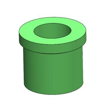
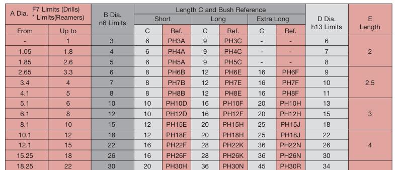
ThedrillbushwasselectedbasedonISO4247(BS1098PT.2 1977 / DIN 172A) standards to ensure precision and durability in repeated drilling operations. A Headed Type, PressFit Bush(PH30H Series) waschosen foritsaccurate drill alignment, firm press-fit into the jig body to prevent displacement,and headsupport for stable positioning and easyreplacement.Theboresizeandlengthwereselectedto match the required drill diameter for machining Lap Joint Flanges(ANSIB16.5),followingISOstandardincrementsto ensurecompatibilitywithdrillsandreamers.
2:
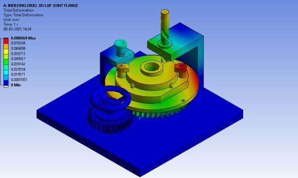
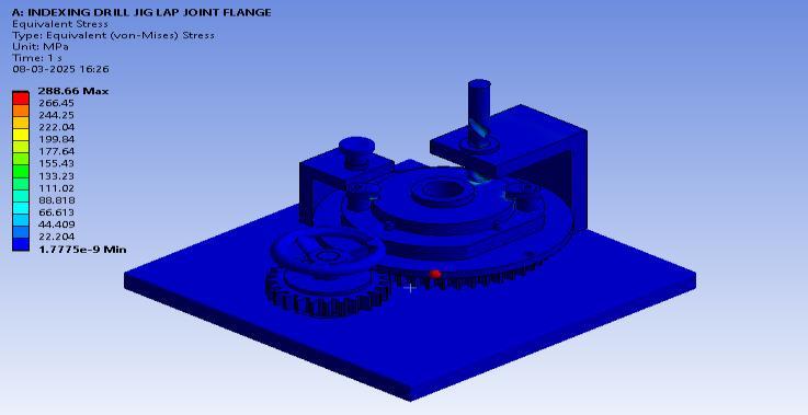
The Finite Element Analysis (FEA) was conducted to evaluate the structural integrity of the drill jig under operationalloads.Theanalysishelpsdeterminethestress distribution,deformation,andoverallsafetyofthedesign. Thetotaldeformationanalysis,asshowninFigure2,reveals amaximumdeformationof0.088mm,whichisminimaland does not affect the precision of the drilling process. This confirms that the jig maintains its alignment throughout multiple drilling operations. Additionally, the Equivalent (Von-Mises)stressdistribution,depictedinFigure3,shows that the maximum stress recorded is 288 MPa, primarily concentrated at critical regions such as the drill bush interfaceandclampingareas.Sincethisstressvalueremains wellbelowtheyieldstrengthofthematerial,thejigoperates withinsafelimits.
ThekeyFEAresultsaresummarizedinTable2:
Table 2: Summary of Finite Element Analysis (FEA) Results
Parameter Value
MaximumStress 288(MPa)
MaximumDeformation 0.088(mm)
Tofurtherassessthestructuralsafetyofthejig,theFactorof Safety(FoS)wascalculatedusingtherelation:
FoS=MaximumAppliedStress/MaterialYieldStrength
FoS=1034/288=3.59
WithanFoSof3.59,thejigoperateswellwithinsafetylimits, ensuringstructuralintegrity,durability,andreliabilityunder machining conditions. The plunger effectively locks the indexingplate,maintainingpreciserotationalpositioningfor accurate hole placement. Additionally, the hook clamps securely hold the workpiece, preventing vibration and misalignmentduringdrilling.Theuniformloaddistribution and controlled clamping pressure minimize stress concentrationsandpreventlocalizedwearatcriticalcontact points. These factors collectively enhance the jig’s performance,longevity,andmachiningaccuracy,makingita robust and efficient solution for precision drilling applications.
4:TotalDeformationAnalysis
International Research Journal of Engineering and Technology (IRJET) e-ISSN: 2395-0056
Volume: 12 Issue: 03 | Mar 2025 www.irjet.net p-ISSN: 2395-0072
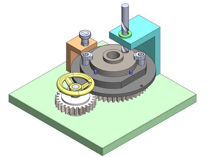
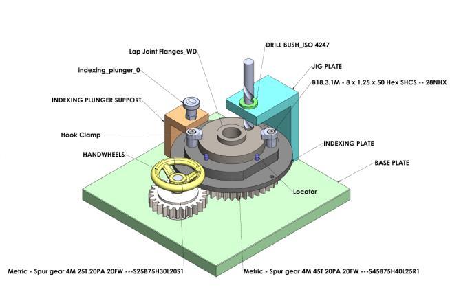
The indexing jig, developed in SolidWorks and shown in Figure4andFigure5,enablesprecisemachiningofASTM A105components.Itconsistsofabaseplate,agear-driven rotary system for controlled positioning, a drill bushing holderforaccuracy,aplungerforsecurelocking,andahook clamp for firm workpiece holding. The plunger ensures positional accuracy, while the hook clamp minimizes vibration.Ahandwheelallowsmanualindexingforuniform holespacing,enhancingefficiency.High-strengthfasteners improve stability, making this jig a reliable solution for preciseholeplacementinmanufacturing.
7. CONCLUSIONS
The Finite Element Analysis (FEA) results validate the structuralintegrityandefficiencyofthedesigneddrilljigfor lapjointflanges.Themaximumstressrecorded(288MPa) remainswellwithinthematerial’syieldstrength,ensuring safeand reliable operation. Minimal deformation of0.088 mm confirms the jig’s precision in maintaining alignment, whileaFactorofSafety(FoS)of3.59guaranteesitsabilityto withstandoperationalloadswithoutfailure.
Additionally, the uniform load distribution and optimized clampingmechanismreducelocalizedwear,enhancinglongtermdurability.Thesedesignfeaturescollectivelyimprove machining accuracy, minimize setup time, and ensure consistentperformanceinprecisiondrillingapplications. Thisstudyestablishesthedrilljigasarobustandeffective solution for machining ASTM A105 components. Future enhancements could explore automation and material optimizations to further improve efficiency and reduce manufacturingcosts.
1. ANSIB16.5-PipeFlangesandFlangedFittings:ASME Standards,2021.
2. ASTM A105 - Standard Specification for Carbon Steel Forgings for Piping Applications, ASTM International, 2020.
3. ISO4247 - Drill Bush Standard Specification, InternationalOrganizationforStandardization,2019.
4. Juvinall,R.C.,&Marshek,K.M.(2018).Fundamentalsof MachineComponentDesign(6thEdition).Wiley.
5. ANSYS 2022 R1 - User Documentation for Finite ElementAnalysis,ANSYSInc.
6. Kalpakjian, S., & Schmid, S. R. (2018). Manufacturing EngineeringandTechnology(7thEdition).Pearson
7. Patel,Smit,Vasoya,Sahil,andJoshi,Ankur."Designand Manufacturing of Jigs for Drilling Machine." International Research Journal of Engineering and Technology(IRJET),Vol.4,Issue3,2017.
8. "Design,FabricationandAutomationofIndexingDrill Jig." International Journal of Scientific & Engineering Research,Vol.9,Issue5,May2018,ISSN2229-5518.
9. "CAD Modelling & Concept Design of Jig Fixture for ConcentricDrilling."InternationalJournalofMechanical Engineering Applications and Research, Vol. 3, No. 2, April2014,ISSN2278–0149.
10. "Design&ManufacturingofDrillingJig."International Journal for Engineering Applications and Technology, Issue6,Volume3,ISSN:2321-8134.
11. "Design and Development of Modified Jig for Angular Drilling on Cylindrical Part." International Research JournalofEngineeringandTechnology(IRJET),Vol.6, Issue3,March2019,e-ISSN:2395-0056,p-ISSN:23950072.
12. "Modelling and Analysis of Drilling Jig for Mounting Casing of Electric Motor." International Journal of
International Research Journal of Engineering and Technology (IRJET) e-ISSN: 2395-0056
Volume: 12 Issue: 03 | Mar 2025 www.irjet.net p-ISSN: 2395-0072
Engineering Research & Technology (IJERT), Vol. 6, Issue2,February2017,ISSN:2278-0181.
13. "Design of Jigs and Fixtures for Hydraulic Press Machine."MalikussalehIndustrialEngineeringJournal, Vol.1,No.1,2012,ISSN2301-934X.
14. "IndexingPlungerGN617-8-A."Elesa+Ganter,Available at:https://www.elesa-ganter.in/en/ind
15. "Hook Clamp." Carr Lane Manufacturing, Available at: https://www.carrlane.com/
16. "DrillBush."Tri-ArdDerbyLtdCatalogue,Availableat: https://www.triard.co.uk/
17. Joshi,P.H.JigsandFixtures,TataMcGraw-Hill,2010.
© 2025, IRJET | Impact Factor value: 8.315 | ISO 9001:2008 Certified
| Page775