
International Research Journal of Engineering and Technology (IRJET) e-ISSN: 2395-0056
Volume: 13 Issue: 02 | Feb 2026 www.irjet.net p-ISSN: 2395-0072
International Research Journal of Engineering and Technology (IRJET) e-ISSN: 2395-0056
Volume: 13 Issue: 02 | Feb 2026 www.irjet.net p-ISSN: 2395-0072
Vivek Arvindbhai Raval1, Deepak Dev2
Abstract – Electrical Vehicle (EV) fast charging station integrating a solar photovoltaic (PV) Generation with Battery Energy Storage System (BESS) present a promising solution to supply clean electrical energy, overcome peak power demand and improve operational economics. We present an optimal design, engineering and techno-Commercially analysis of a solar + BESS powered EV Fast Charging station suitable for India Urban and Semi – Urban Environments.
Key Words: Electrical Vehicle (EV) fast is charging station, solar photovoltaic (PV) Plant, Battery Energy Storage System (BESS).
IntegratingsolarplantsandBatteryEnergyStorageSystems (BESS) into fast EV charging stations in India is a pivotal strategytoaddressgridconstraints,enhancesustainability, and improve economic viability. This integrated approach enablesamoreresilientandefficiente-mobilityecosystem.
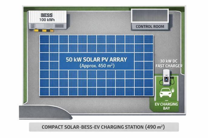
Solarpowerisintermittent.BESSstoresexcesssolarenergy generatedduringpeaksunlighthoursandmakesitavailable foruseduringthenight,cloudyperiods,orpeakEVcharging times.Thismaximizestheconsumptionofclean,renewable energy,makingEVchargingtruly"green"andaligningwith India'sclimateobjectives.
By storing cheaper solar or off-peak grid electricity, chargingstationoperatorscanavoiddrawingpowerfrom the grid during expensive peak-rate periods (time-of-use tariffs).This"peakshaving"significantlylowersoperational costs,whichcanbepassedontoconsumersasmorecosteffectivechargingrates.
Inareaswithanunreliablegridorfrequentpoweroutages, BESSprovidesareliableemergencypowersource,ensuring uninterruptedchargingservices.Thisisespeciallycrucialfor highwaystationsorcriticalfleetoperations.
Off-grid solar-BESS configurations allow for the establishment of fast-charging stations in remote or rural areaswheregridconnectivityislimitedorcostlytoupgrade, promotingwiderEVadoptionacrossIndia.
Advancedcontrolsystemswithintheintegratedsetupcan provide power factor correction and harmonics filtering, ensuring a stable and clean power supply that protects sensitiveEVchargingequipmentandthegriditself
1.1
Fast charging demands high power instantly, which can strain the local grid and cause instability (e.g., voltage fluctuations). BESS acts as a buffer, storing energy and deliveringitrapidlytoEVs,thusreducingsuddenpeakloads onthemaingridinfrastructure.
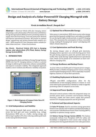
2.1 Solar PV System: Sizedtomaximizeenergygeneration basedonsite-specificsolarirradianceanddemandprofiles.It usesinverterswithMaximumPowerPointTracking(MPPT) capabilitytooptimizeenergycapture.
2.2 Battery Energy Storage System (BESS): The battery (commonly Lithium Iron Phosphate (LFP) for safety and durability) is integrated to store excess solar energy and providepowerduringpeakdemandorlowsolargeneration.
International Research Journal of Engineering and Technology (IRJET) e-ISSN: 2395-0056
Volume: 13 Issue: 02 | Feb 2026 www.irjet.net p-ISSN: 2395-0072
2.3 Power ConversionSystem(PCS):Acrucialbidirectional converterthatmanagestheflowofenergybetweentheAC grid, DC solar panels, DC battery storage, and DC fast chargers. It performs DC-to-AC and AC-to-DC conversion efficiently.
2.4 EV Fast Chargers: These are DC fast chargers, with power ratings typically ranging from 50kW upwards, designedtorapidlychargehigh-voltageEVs.
2.5 Smart Energy Management Systems(EMS):Intelligent softwareandcontrolalgorithmsareessentialformanaging theflowofpoweramongthesolarplant,BESS,thegrid,and the EVs. EMS optimizes charging schedules based on solar availability, battery state of charge (SOC), and real-time electricityprices.
2.6 Main Low-Voltage Panel: Thecentralconnectionpoint forallcomponentsandthegridconnection.
3. Step-by-Step Working Principle
3.1 Solar Energy Generation (DC Power): Photovoltaic (PV) panels convert sunlight directly into Direct Current (DC)electricity.AnMPPT(MaximumPowerPointTracking) controller is typically used to optimize the power output fromthepanelsbasedoncurrentweatherconditions.
3.2 Power Conversion (DC to AC/DC):
1. ThegeneratedDCpowerneedsconditioning.APower Conversion System (PCS), essentially a sophisticated bidirectionalinverter,managesthisprocess.
2. For use within the station's DC infrastructure (e.g., charging the battery or directly powering DC fast chargers),theDCpowerisroutedappropriately.
3. IfexcessenergyistobesenttotheACutilitygrid,the PCSconvertsDCpowertoACpower.
3.3 Energy Storage and Management (BESS & EMS):
1. TheBESSstoresexcessenergythatisnotimmediately usedbyEVsduringpeaksolarhours.
2. TheEMS,whichactsasthecentralbrain,dynamically decides where power should flow based on a set of rules and real-time data (e.g., time of day, electricity prices,EVdemand,BatteryStateofCharge).
3. WhenEVchargingdemandislowandsolarproduction ishigh,theEMSdirectspowertotheBESSorbackto thegridforpotentialrevenue(energyarbitrage).
3.4 Fast Charging Operation:
2. The EMS ensures the required high power for fast charging is met instantly by prioritizing energy from the BESS and the grid simultaneously, thereby achieving "peak shaving" and preventing demand spikesonthemaingrid.
3. The high-power DC is then delivered directly to the EV'sbattery.
3.5 Grid Interaction and Resilience:
1. Thesystemcandrawpowerfromthegridduringoffpeak hours when electricity is cheaper to charge the BESS.
2. In the event of a grid outage, the BESS provides immediate backup power, ensuring uninterrupted service for critical charging operations (microgrid functionality)
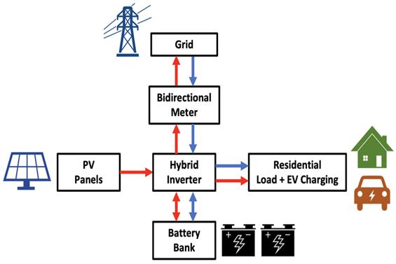
3.6 Operational Modes
1 SolarDirectMode:SolarpowerdirectlychargesEVsor theBESSwhenavailable.
2 PeakShavingMode:BESSdischargesstoredenergyto supplementsolarandgridpowerduringhigh-demand periods,avoidingexpensivepeaktariffs.
3 Grid Charging Mode: BESS is charged from the grid duringoff-peak,low-costhours.
4 Backup Mode: BESS provides power to the station in caseofagridfailure,ensuringresilience.
5 Grid Export Mode: If allowed by regulations and the BESSisfull,surplussolarenergycanbeexportedtothe gridforcredit.
1. WhenanEVplugsin,thechargercommunicateswith the vehicle's Battery Management System (BMS) to determineitschargingneeds(voltage,current,Stateof Charge).
International Research Journal of Engineering and Technology (IRJET) e-ISSN: 2395-0056
Volume: 13 Issue: 02 | Feb 2026 www.irjet.net p-ISSN: 2395-0072
Thetechnicaloperationreliesonsophisticatedmanagement andcontrolsystems:
Peak Shaving and Demand Control: The BESS supplies powerduringhigh-demandperiodstopreventthestation's totalconsumptionfromexceedingthecontractedgridlimit, thusavoidingpenaltiesandreducinginfrastructureupgrade costs.
Energy Arbitrage: TheEMSchargestheBESSwithcheaper, off-peak grid electricity or solar energy and discharges it duringexpensivepeak-rateperiodstominimizeoperational expenses.
Power Quality Management: The BESS and PCS help maintain grid stability by providing voltage regulation, powerfactorcorrection,andfilteringharmonicdistortions causedbyfastchargers.
Power Balance and Control Algorithms: The system operatesonpowerbalanceequations,wheretheBESSfills thegapbetweenthepower demandedbyEVchargersand thepoweravailablefromthegridandsolarPVatanygiven time
4. Key Mathematical Equations and Graphs for Solar + BESS EV Charging
5.1 Essential Mathematical Equations
I. PV Generation Equation
ThePVoutputiscalculatedusingirradianceand performanceratio:
P_PV(t) = P_rated × G(t) × PR
Where:
-P_rated=PVsystempeakcapacity
-G(t)=Irradiance(normalized)
-PR=PerformanceRatio
II. Battery SOC Equation
ThebatteryStateofChargeisupdatedeachtime-step as:
SOC(t+Δt) = SOC(t) + (η_ch × P_ch − P_dis / η_dis) × Δt / E_batt
Thismodelscharging,discharging,andlossfactors.
III. Power Balance Equation
TheEVchargingstationfollowsthispowerbalance: P_load = P_PV→load + P_BESS→load + P_grid
Thisensuresallpowersuppliedequalsdemand.
IV. Peak Shaving Constraint
Toprotectthegridandreducedemandcharges: P_Grid(t) ≤ P_Threshold
Operational Resilience: TheBESSprovidesreliablebackup power,ensuringuninterruptedserviceevenifthemaingrid experiencesanoutage.
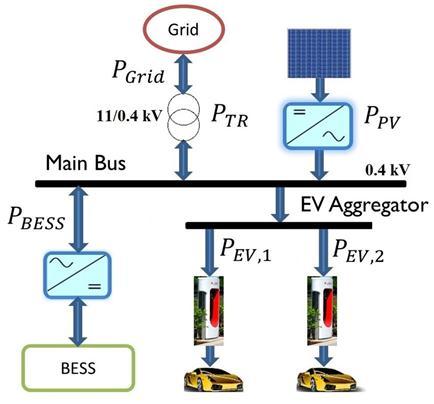
3: Power flow and control strategy of the solar + BESS EV charging micro grid
Batterydischargeswhenloadexceedsthis threshold.
5.2 Key Graphs with Short Explanations
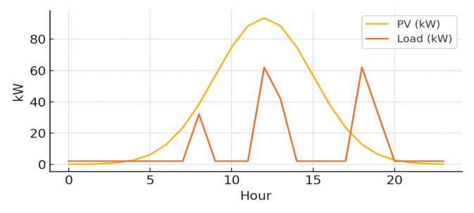
Chart 1: Solar PV output and EV charging load profile
ThisgraphcompareshourlyPVgenerationwithEVcharging demand.Peaksinloadcorrespondtofast-chargingevents. PV supports midday charging, while evening charging requiresbatteryorgrid.
Volume: 13 Issue: 02 | Feb 2026 www.irjet.net
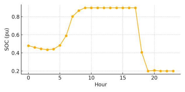
Chart 2: Battery state of charge (SOC) variation over a typical day
The SOC curve shows battery charging during high PV generation and discharging in the evening to support chargingwhilelimitingthegriddraw.
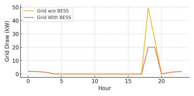
Chart 3: Grid power draw comparison with and without BESS
This plot shows how the battery dramatically reduces maximumgriddraw.WithoutBESS,griddemandspikesup to49kW;withBESS,itislimitedtothethresholdof20kW (peakshaving).
6. System Description (Realistic India-Based Site)
Table 1: System Specifications (Realistic India-Based Site) Solar
12 PM – 3 PM (Peak Sun Hours) Solar
– 50 KW
directly powers EV charger (30 kW)
Extra solar (15–20 kW) →
6 PM – 9 PM (Evening Peak Period Real Problem Time) Solar Generation 0 KW
Charging load
KW
Table 3 Cloudy / Rainy Day Real Example
9 AM – 6 PM (Solar generation drops drastically)
Solar Generation
KW – 10 KW
9
Table 2 Real-Time Operation (HOUR–BY–HOUR)
(Morning
6.1 Daily Energy Summary (REAL VALUES)
Table 4: Daily Energy Summary
Component Daily Contribution
Solar (50 kW) 180–200 kWh/day
Battery (100 kWh) 1 full cycle/day
–80 kWh/day
International Research Journal of Engineering and Technology (IRJET) e-ISSN: 2395-0056
Volume: 13 Issue: 02 | Feb 2026 www.irjet.net p-ISSN: 2395-0072
6.2 Financial Benefit (Approx. India Values)
Table 5: FinancialBenefitAnalysis(IndiaValues)
Component
Without Solar + Battery 250–260 kWh/day grid use
Cost ₹2,250 per day
With Solar + Battery Only 60–80 kWh/day grid use
Cost ₹540–720 per day
Daily Saving ₹1,500–1,700 saved per day
Yearly Saving ₹5.5–6.0 lakh saved per year
7. Safety Considerations
1) Electrical Safety:- Fast chargers (30–350 kW), highvoltage batteries, and solar inverters create complex electricalenvironments.
Properearthing/groundinginlinewithCEAregulations
Surgeprotectiondevices(SPD)forDCandACsides
Arc-faultdetection(especiallyinlargesolarDCruns)
IsolatorsandDCdisconnectsforemergencyshutdown
Short-circuitprotectioninBESSandchargercircuits
Propercablesizing&thermalprotection
2) Battery Energy Storage Safety: - BESS is the most sensitivecomponentduetofirerisk.
BatteryManagementSystem(BMS)with: Cellbalancing,Over-charge/over-dischargeprotection, Thermalrunawaydetection
Firedetectionandsuppressionsystems
Aerosol-based fire suppression, Novec, FM200, or Equivalentagents
Thermalmanagement: Air-cooledorliquid-cooledsystems
Hazardousgasventilation EspeciallyforLFP/NMCchemistries
Compliancewithstandardslike: IEC62619(batterysafety) IEC62933(BESSsystems) CEAsafetyguidelinesinIndia
3) Solar Plant Safety
Anti-islandingprotection
Stringmonitoringforearlyfaultdetection
Properinsulationandcableroutingtoavoidhotspots
Use of MC4-certified connectors to prevent thermal incidents
Periodic cleaning + maintenance (especially in dusty Indianenvironments)
4) EV Charger Safety
Overcurrentandovervoltageprotection
Liquid-cooledchargingcablesfor200–500Aoutput
Automaticemergencystop(E-Stopbutton)
Real-timemonitoringofconnectortemperature
IP55–IP65weatherproofenclosures
Groundfaultdetection(RCDprotection)
5) Fire & Thermal Safety
Firezonesclearlyseparated(solar,BESS,chargerarea)
Thermalcamerasforearlyfiredetection
Fireextinguishersratedforelectrical&lithiumfires
24/7remotemonitoring+SCADAalarms
6) Regulatory & Compliance Requirements (India)
CEA(CentralElectricityAuthority)safetyrules
IECstandardsforsolar,BESS,andEVchargers
BISrequirementsforchargerandbatteryequipment
DISCOMinterconnectionrules
FireNOCforBESSinstallations
This research paper presented the design, operational analysis, and techno-economic evaluation of a solarpowered EV fast-charging microgrid integrated with a Battery Energy Storage System (BESS), specifically tailored for Indian urban and semi-urban conditions. The study demonstrates that combining solar PV with BESS effectivelyaddressesthemajorchallengesassociatedwith fast EV charging, including high peak demand, grid constraints,energycostvolatility,andsupplyreliability.
Through detailed system modeling, operational modes, mathematical formulations, and real-time hour-by-hour analysis,itisshownthattheproposedsolar-BESSmicrogrid significantly reduces grid dependency while ensuring uninterrupted high-power charging. Peak shaving and energyarbitragestrategiesimplementedviaasmartEnergy Management System (EMS) successfully limit grid draw within contracted limits, prevent demand penalties, and enhance overall grid stability. The battery system plays a critical role in buffering intermittentsolargeneration and supplyinginstantpowerduringpeakchargingperiodsand gridoutages.
TheIndia-basedcasestudyconfirmsthataproperlysized 50 kW solar PV system with a 100 kWh BESS can supply approximately 70–75% of the daily energy demand ofa DC fast-charging station, reducing grid consumption by nearly 70%. The financial analysis highlights substantial operational cost savings of 5.5–6.0 lakh per year, demonstrating strong economic feasibility alongside environmentalbenefits.
Additionally, the paper emphasizes essential safety, regulatory,andcomplianceconsiderationsalignedwith CEA,
International Research Journal of Engineering and Technology (IRJET) e-ISSN: 2395-0056
Volume: 13 Issue: 02 | Feb 2026 www.irjet.net p-ISSN: 2395-0072
IEC, BIS, IESA and DISCOM guidelines, reinforcing the practical deploy ability of such systems in real-world conditions. The proposed architecture also enables deploymentinremoteorweak-gridareas,supportingIndia’s broader objectives of EV adoption, renewable integration, andenergyresilience
Although the proposed solar-powered EV charging microgridwithBESSistechnicallyfeasible,thetechnologyis still under active research and development. Ongoing advancementsinbatterychemistry,powerelectronics,and energy management systems are expected to improve performance and reliability. With declining battery costs, large-scale manufacturing, and supportive policies, this technologyisprojectedtobecomesignificantlymorecosteffectiveandwidelydeployableinthenearfuture.
Inconclusion,solar-poweredEVchargingmicrogridswith integrated BESS represent a technically robust, economically viable, and environmentally sustainable solution forfutureEVinfrastructureinIndia.Thefindingsof this study can serve as a reference framework for policymakers,charginginfrastructuredevelopers,utilities, and researchers aiming to scale fast-charging networks while minimizing grid impact and maximizing renewable energyutilization.
BIOGRAPHIES


Vivek Arvindbhai Raval
Qualification:M.TechinEPS
(ElectricalPowerSystem)
Designation:AssistantManager
Deepak Dev
Qualification:B.TechinEE (ElectricalEngineering)
Designation:Sr.Engineer