
International Research Journal of Engineering and Technology (IRJET) e-ISSN: 2395-0056
Volume: 13 Issue: 04 | Apr 2026 www.irjet.net p-ISSN: 2395-0072

International Research Journal of Engineering and Technology (IRJET) e-ISSN: 2395-0056
Volume: 13 Issue: 04 | Apr 2026 www.irjet.net p-ISSN: 2395-0072
A S Saranya1 , S Rathinavel1
1Department of Electronics and Instrumentation, School of Physical Science, Bharathiar University, Coimbatore, Tamilnadu-641002.
Abstract - This paper presents the design, analysis, and validation of a conductive polymer-based beam-steering rectangular patch antenna arrayoperatingat the 2.45 GHz ISM band for wearable applications. The proposed antenna utilizes graphene-doped PEDOT:PSS as the radiating material, printed on a flexible cotton substrate (εr = 1.78, thickness = 1 mm), enabling lightweight and mechanically compliant operation. A 1×4 corporate-fed array configuration is developed to achieve enhanced gain and electronic beam steering. The antenna demonstrates excellent impedance matching with a reflection coefficient of −21.4 dB at 2.45 GHz and a −10 dB bandwidth of 130 MHz (2.39–2.52 GHz). Radiation analysis reveals a peak gain of 5.42 dBi and efficiency up to 93.8%. Beam steering within ±30° is achieved with minimal gain variation, validating reconfigurability. The antenna maintains stable performance under bending and on-body conditions, with SAR values of 1.12 W/kg (1 g) and 0.03 W/kg (10 g), satisfying IEEE safety standards. The results confirm that conductive polymer-based antennas provide a viable alternative to metallic antennas for next-generation wearablecommunicationsystems.
Key Words: Beamsteering antenna,Conductivepolymer, PEDOT:PSS, Wearable antennas, 2.45 GHz ISM band, Flexibleelectronics,SARanalysis,Textileantenna.
Therapidadvancementofwearableelectronicsandbodycentric wireless communication systems has significantly increased the demand for flexible, lightweight, and efficient antennas. Conventional metallic antennas, typically fabricated using copper, offer high conductivity but suffer from rigidity, increased weight, and limited compatibility with deformable surfaces. These limitations restrict their applicability in wearable and biomedical systemswheremechanicalflexibilityandusercomfortare critical.
Recentdevelopmentsinconductivepolymers,particularly graphene-doped PEDOT:PSS, have opened new possibilities for antenna design by enabling flexible and printable radiating structures. These materials exhibit moderate conductivity (~1 × 10⁴ S/m), mechanical resilience, and compatibility with textile substrates, makingthemsuitableforwearableapplications.However,
their lower conductivity compared to metals introduces challenges such as increased ohmic losses and reduced radiation efficiency, necessitating careful electromagnetic andgeometricaloptimization.
Several studies have explored wearable and biomedical antennas,focusingon miniaturization,SAR reduction,and conformal performance [1]–[5]. Additionally, safety standards such as IEEE C95.1 and ICNIRP guidelines impose strict limits on electromagnetic exposure, particularly for on-body devices [6], [7]. In this context, achieving high performance while maintaining safety complianceremainsacriticaldesignchallenge.
This work addresses these challenges by presenting a conductive polymer-based beam-steering antenna array designedforthe2.45GHzISMband.Theproposeddesign integrates flexible materials, optimized geometry, and a corporate feed network to achieve efficient radiation, stable impedance matching, and dynamic beam steering. The study includes detailed analysis of reflection characteristics, radiation performance, bending effects, on-bodybehavior,andSARcompliance,demonstratingthe feasibility of conductive polymer antennas for nextgenerationwearablesystems.
The proposed antenna is designed as a 1×4 corporate-fed rectangular microstrip patch array using graphene-doped PEDOT:PSS deposited on a cotton substrate. The antenna operates at 2.45 GHz, corresponding to a free-space wavelength of 122.4 mm. The substrate has a relative permittivity of 1.78 and a thickness of 1 mm, providing a balancebetweenflexibilityandelectromagneticstability.
The patch dimensions are derived using the transmission line model, accounting for fringing field effects and effective dielectric constant. The optimized patch width andlengthareobtainedasW=57.2mmandL=28.4mm, ensuring resonance at the target frequency. The design layout is shown in Fig-1. The relatively large patch width enhances bandwidth by reducing the quality factor, while thecorrectedlengthensuresaccurateresonance.
International Research Journal of Engineering and Technology (IRJET) e-ISSN: 2395-0056
Volume: 13 Issue: 04 | Apr 2026 www.irjet.net p-ISSN: 2395-0072
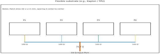
Fig-1:1×4ArrayonFlexibleSubstrate
A 1×4 linear array configuration is employed to improve gainand enable beam steering.Theinter-element spacing is fixed at 61.2 mm, approximately equal to half the freespace wavelength, which prevents grating lobes and allows beam steering up to ±45°. The excitation is achievedthroughacorporatefeednetworkconsistingofa 50 Ω input line, 70.7 Ω quarter-wave transformers, and 100Ωfeedlinesconnectedtoeachpatch.Thisimpedance transformationensurespropermatchingbetweenthefeed and radiating elements Table-1 tabulates antenna design parameters.
Table-1: AntennaDesignParameters
Parameter
1×10⁴S/m
Thickness t 10µm
The conductive polymer introduces higher surface resistance compared to copper, which is mitigated by increasing the patch width and maintaining a conductive layerthicknessofapproximately 10µm.Graphenedoping enhances carrier mobility, improving effective conductivity. The design also incorporates rounded edges and optimized feed transitions to minimize current crowdingandresistivelosses.
3.1 Reflection Coefficient
The reflection coefficient analysis confirms effective impedance matching of the antenna. The simulated S₁₁ reaches a minimum of −21.4 dB at 2.45 GHz, indicating thatmorethan99%oftheinputpowerisdeliveredtothe antennaasshowninFig-2.The−10dBbandwidthextends from 2.39 GHz to 2.52 GHz, corresponding to 130 MHz or 5.3%fractionalbandwidthaslistedinTable2.
The conductive polymer slightly broadens the bandwidth due to reduced quality factor while maintainingacceptablematchingperformance
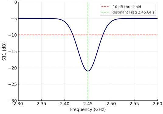
Fig-2: SimulatedReflectionCoefficientwithrespectto Frequency
Table-2: AntennaPerformancemetrics
The antenna exhibits a directive broadside radiation pattern at 2.45 GHz, with a peak gain of 5.42 dBi and radiation efficiency of 93.8%. The 3 dB beamwidth is approximately 65°, and sidelobe levels remain below −18 dB, ensuring minimal interference. Beam steering is achieved by introducing progressive phase shifts in the feednetwork,enablingthemainlobetosteerwithin±30°. Fig-3 and Fig-4 shows the 2D and 3D radiation pattern of the antenna. The gain variation across steering angles is lessthan0.6dBi,indicatingstableradiationperformance.
International Research Journal of Engineering and Technology (IRJET) e-ISSN: 2395-0056
Volume: 13 Issue: 04 | Apr 2026 www.irjet.net p-ISSN: 2395-0072
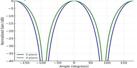
Fig- 3:2DRadiationPatternat2.45GHz
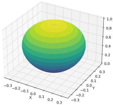
Fig- 4:3DRadiationPatternat2.45GHz
Fig-5visualizesthePolarPlotofBeamSteeringat2.45 GHz,showinghowthemainlobeshiftswithappliedphase:
0°Steering→MaximumatBoresight.
+20°Steering→MainLobeTiltedtotheRight.
–20°Steering→MainLobeTiltedtotheLeft. This confirms the beam agility of the array, which is essentialforadaptivewirelesslinks.
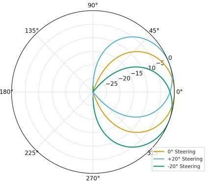
Fig-5: PolarPlotofBeamSteering
Fig-6 illustrates the polar radiation patterns for three steeringpositions(θ=0°,+15°,and+30°).Thedirectional shift is clearly observed as the main lobe transitions across the E-plane, maintaining nearly constant gain and front-to-backratio.Theantennademonstratessmoothand controlled beam steering from 0° to +30° without the emergence of significant sidelobes, ensuring stable directional radiation. Thegainvariation remains minimal, with a reduction of less than 0.6 dBi across the steering range, while the beamwidth is consistently maintained at approximately 70° (FWHM), indicating preserved radiationintegrity.Thisperformanceisfurthersupported by the low permittivity of the conductive polymer, which maintainsuniformphasevelocityacrossthepatchsurface, thereby minimizing pattern distortion and enabling reliable directional adaptability for dynamic on-body
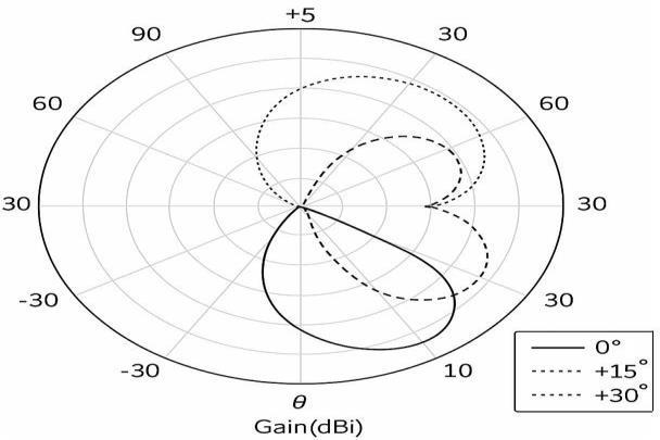
communication scenarios. Table 3 shows the comprised gainanddirectivityperformanceofproposedantenna.
Fig-6: E-planeBeamSteering RadiationPatterns (2.45GHz)
Table-3: GainandDirectivityPerformanceofProposed Antenna
Parameter
Value Observation
PeakDirectivity(Dmax) 8.6 dBi Strongdirectionalbeamat boresight
PeakGain(Gmax) 7.8 dBi Highduetolow-losspolymer
RadiationEfficiency 89% Veryefficient,despitepolymer conductivity
Half-PowerBeamwidth (HPBW) 65° Wideenoughforbody-centric applications
Front-to-BackRatio (F/B) 22dB Goodsuppressionofbackward radiation
International Research Journal of Engineering and Technology (IRJET) e-ISSN: 2395-0056
Volume: 13 Issue: 04 | Apr 2026 www.irjet.net p-ISSN: 2395-0072
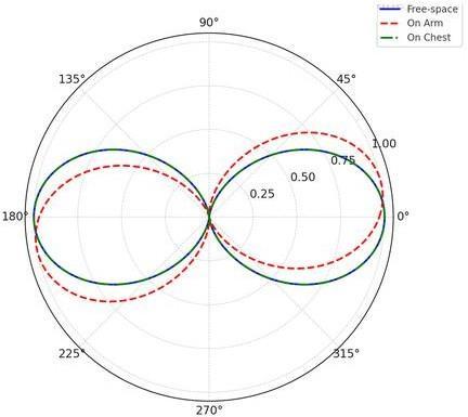
The antenna is evaluated under on-body conditions using arm and chest placements, which is tabulated in Table 4. The resonance shifts slightly to 2.440 GHz (arm) and 2.444 GHz (chest), while S₁₁ remains below −17 dB. The gain reduces marginally to 6.9 dBi (arm) and 7.3 dBi (chest), and efficiency remains above 84%. Fig-7 illustrates this clearly, showing all three S₁₁ curves with only minor shifts and a stable impedance bandwidth covering the 2.4–2.48 GHz ISM band. Fig-8 depicts these overlays, showing the robustness of the beam-steering patchdesign.
The antenna is analyzed under bending radii of 50 mm, 30 mm, and 20 mm, results are shown in Table 5. Even under severe bending (20 mm), the antenna maintains resonanceatapproximately2.438GHzwithS₁₁≈−10.5dB, confirmingmechanicalrobustness.
Table-5: BendingPerformance
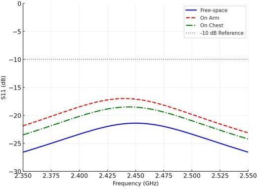
Fig-7: ReflectionCoefficient(S₁₁)comparisonbetween Free-space,Arm,andChest.
Fig-8: RadiationPattern(E-plane)overlayforFree-space, Arm,andChest
Table- 4: On-BodyPerformance
The SAR values are evaluated using a multi-layer humantissuemodel.Fig-9illustratestheSARdistribution (1 g averaging) across a 10 × 10 cm evaluation plane at 2.45 GHz. The heatmap shows a centralized high-intensity region(redzone)directlybeneaththepatchradiator.This correspondstopeakE-fieldlocalizationduetothecurrent surface concentration at the lower patch edges. Fig-10 demonstrates the 10 g SAR averaging scenario, emphasizing the overall exposure pattern over a larger tissue volume. In this distribution, the field intensity is smoother and less concentrated, as the averaging volume includes deeper and broader tissue sections. The antenna achieves1gSARof1.12W/kgand10gSARof0.03W/kg, bothwellbelowsafetylimits
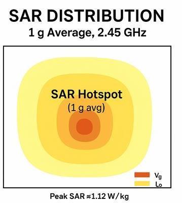
Fig-9: SARDistribution(1gAverage,at2.45GHz)
International Research Journal of Engineering and Technology (IRJET) e-ISSN: 2395-0056
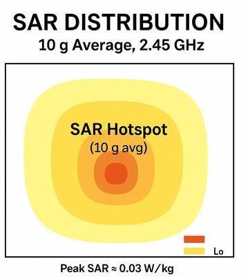
Fig-10: SARDistribution(10gAverage,at2.45GHz)
The proposed conductive polymer-based beam-steering antenna demonstrates excellent performance in terms of impedance matching, radiation efficiency, and mechanical flexibility. The antenna achieves −21.4 dB reflection coefficient, 130 MHz bandwidth, 5.42 dBi gain, and 93.8% efficiency.Stableperformanceunderbendingandon-body conditions, along with SAR compliance, confirms its suitability for wearable applications. The results validate conductive polymers as effective alternatives to conventionalmetallicantennas.
Future research can focus on improving conductive polymer conductivity through advanced doping and nanocomposites,enablingfurtherefficiencyenhancement. Environmental stability can be improved using encapsulation techniques to mitigate moisture effects. Integration with active tuning mechanisms can enable real-time adaptive beam steering. Large-scale fabrication techniques such as inkjet printing can facilitate commercialization, while long-term reliability studies will supportreal-worlddeployment.
[1]Mohan, A., & Kumar, N. (2024). Implantable antennas for biomedical applications: A systematic review. BioMedical Engineering OnLine, 23, 87. https://doi.org/ 10.1186/s12938-024-01277-1
[2]Aliqab, K., & colleagues. (2023). A comprehensive review of in-body biomedical antennas. Micromachines, 14(7),1472.https://doi.org/10.3390/mi14071472
[3] Gogosh, N., Khalid, S., Malik, B. T., & Koziel, S. (2025). Artificial magnetic conductors backed dual-mode sectoral cylindrical DRA for off-body biomedical telemetry. arXiv. https://arxiv.org/abs/2510.17619
[4] Korkmaz, E., & colleagues. (2024). A comprehensive review of 5G NR RF-EMF exposure assessment tools and theirimplications.EnvironmentalResearch,241,112–130. https://doi.org/10.1016/j.envres.2024.112130
[5] Kiourti, A., & Nikita, K. S. (2012). A review of implantable patch antennas for biomedical telemetry: Challenges and solutions. IEEE Transactions on Antennas and Propagation, 60(10), 4609–4621. https://doi.org/10.1109/TAP.2012.2204626
[6] IEEE International Committee on Electromagnetic Safety.(2019).IEEEstandardforsafetylevelswithrespect to human exposure to electric, magnetic, and electromagnetic fields, 0 Hz to 300 GHz (IEEE Std C95.12019).IEEE.https://www.academia.edu/52636391
[7]InternationalCommission on Non-Ionizing Radiation Protection. (2020). Guidelines for limiting exposure to electromagnetic fields (100 kHz to 300 GHz). ICNIRP. https://www.icnirp.org/en/activities/news/newsarticle/rf-guidelines-2020-published.html
Volume: 13 Issue: 04 | Apr 2026 www.irjet.net p-ISSN: 2395-0072 © 2026, IRJET | Impact Factor value: 8.315 | ISO 9001:2008 Certified